Page 10 of 2248
B2M0168
2) Take out purge control solenoid valve through the bot-
tom of the intake manifold.
3) Disconnect connector and hoses from purge control
solenoid valve.
4) Installation is in the reverse order of removal.
Tightening torque:
16±1.5 N⋅m (1.6±0.15 kg-m, 11.6±1.1 ft-lb)
B2M0423
5. EGR Valve
A: REMOVAL AND INSTALLATION
1) Disconnect vacuum hose from EGR valve.
2) Remove bolts which install EGR valve onto intake mani-
fold.
3) Installation is in the reverse order of removal.
CAUTION:
Replace gasket with a new one.
Tightening torque:
17.1 — 20.1 N⋅m (1.74 — 2.05 kg-m, 12.6 — 14.8
ft-lb)
B2M0424
6. Back-Pressure Transducer (BPT)
A: REMOVAL AND INSTALLATION
1) Disconnect vacuum hoses from BPT.
2) Remove BPT from bracket.
3) Installation is in the reverse order of removal.
7
2-1SERVICE PROCEDURE
4. Purge Control Solenoid Valve - 6. Back-Pressure Transducer (BPT)
Page 11 of 2248
B2M0168
2) Take out purge control solenoid valve through the bot-
tom of the intake manifold.
3) Disconnect connector and hoses from purge control
solenoid valve.
4) Installation is in the reverse order of removal.
Tightening torque:
16±1.5 N⋅m (1.6±0.15 kg-m, 11.6±1.1 ft-lb)
B2M0423
5. EGR Valve
A: REMOVAL AND INSTALLATION
1) Disconnect vacuum hose from EGR valve.
2) Remove bolts which install EGR valve onto intake mani-
fold.
3) Installation is in the reverse order of removal.
CAUTION:
Replace gasket with a new one.
Tightening torque:
17.1 — 20.1 N⋅m (1.74 — 2.05 kg-m, 12.6 — 14.8
ft-lb)
B2M0424
6. Back-Pressure Transducer (BPT)
A: REMOVAL AND INSTALLATION
1) Disconnect vacuum hoses from BPT.
2) Remove BPT from bracket.
3) Installation is in the reverse order of removal.
7
2-1SERVICE PROCEDURE
4. Purge Control Solenoid Valve - 6. Back-Pressure Transducer (BPT)
Page 12 of 2248
B2M0425A
7. EGR Solenoid Valve
A: REMOVAL AND INSTALLATION
1) Remove bolt which installs EGR solenoid valve onto
intake manifold.
2) Disconnect hoses and connector from EGR solenoid
valve.
NOTE:
This figure shows the rear side of intake manifold.
3) Installation is in the reverse order of removal.
Tightening torque:
19±5 N⋅m (1.9±0.5 kg-m, 13.7±3.6 ft-lb)
8
2-1SERVICE PROCEDURE
7. EGR Solenoid Valve
Page 20 of 2248
G2M0093
4) Connect oil pressure gauge hose to cylinder block.
5) Start the engine, and measure oil pressure.
Oil pressure:
98 kPa (1.0 kg/cm
2,14 psi) or more at 800 rpm
294 kPa (3.0 kg/cm2, 43 psi) or more at 5,000 rpm
CAUTION:
�If oil pressure is out of specification, check oil
pump, oil filter and lubrication line.
�If oil pressure warning light is turned ON and oil
pressure is in specification, replace oil pressure
switch.
NOTE:
The specified data is based on an engine oil temperature
of 80°C (176°F).
6) After measuring oil pressure, install oil pressure switch.
Tightening torque:
25±3 N⋅m (2.5±0.3 kg-m, 18.1±2.2 ft-lb)
7) Install generator and V-belt in the reverse order of
removal, and adjust the V-belt deflection.
8
2-2
6. Engine Oil Pressure
Page 25 of 2248
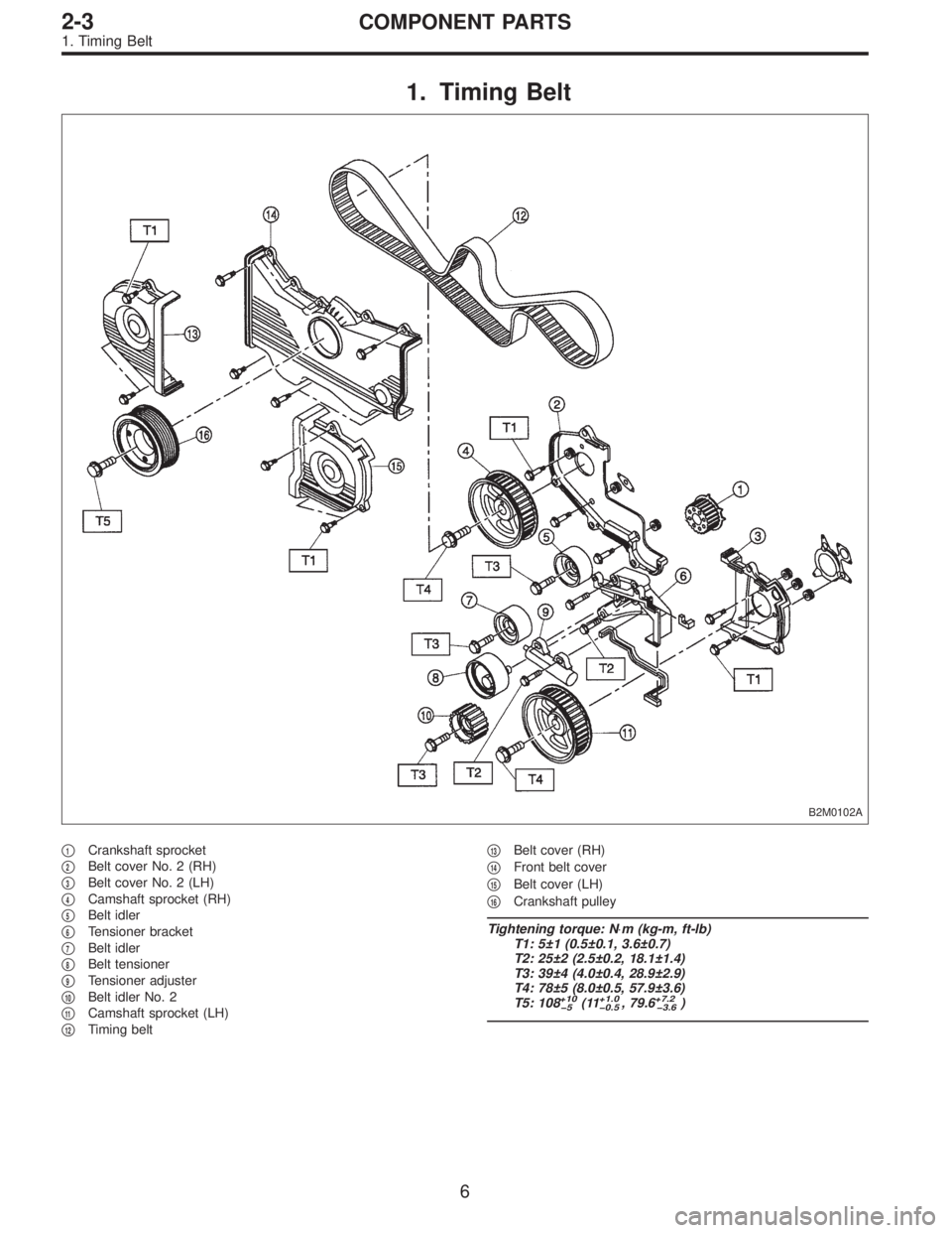
1. Timing Belt
B2M0102A
�1Crankshaft sprocket
�
2Belt cover No. 2 (RH)
�
3Belt cover No. 2 (LH)
�
4Camshaft sprocket (RH)
�
5Belt idler
�
6Tensioner bracket
�
7Belt idler
�
8Belt tensioner
�
9Tensioner adjuster
�
10Belt idler No. 2
�
11Camshaft sprocket (LH)
�
12Timing belt�
13Belt cover (RH)
�
14Front belt cover
�
15Belt cover (LH)
�
16Crankshaft pulley
Tightening torque: N⋅m (kg-m, ft-lb)
T1: 5±1 (0.5±0.1, 3.6±0.7)
T2: 25±2 (2.5±0.2, 18.1±1.4)
T3: 39±4 (4.0±0.4, 28.9±2.9)
T4: 78±5 (8.0±0.5, 57.9±3.6)
T5: 108
+10
�5(11+1.0
�0.5, 79.6+7.2
�3.6)
6
2-3COMPONENT PARTS
1. Timing Belt
Page 26 of 2248
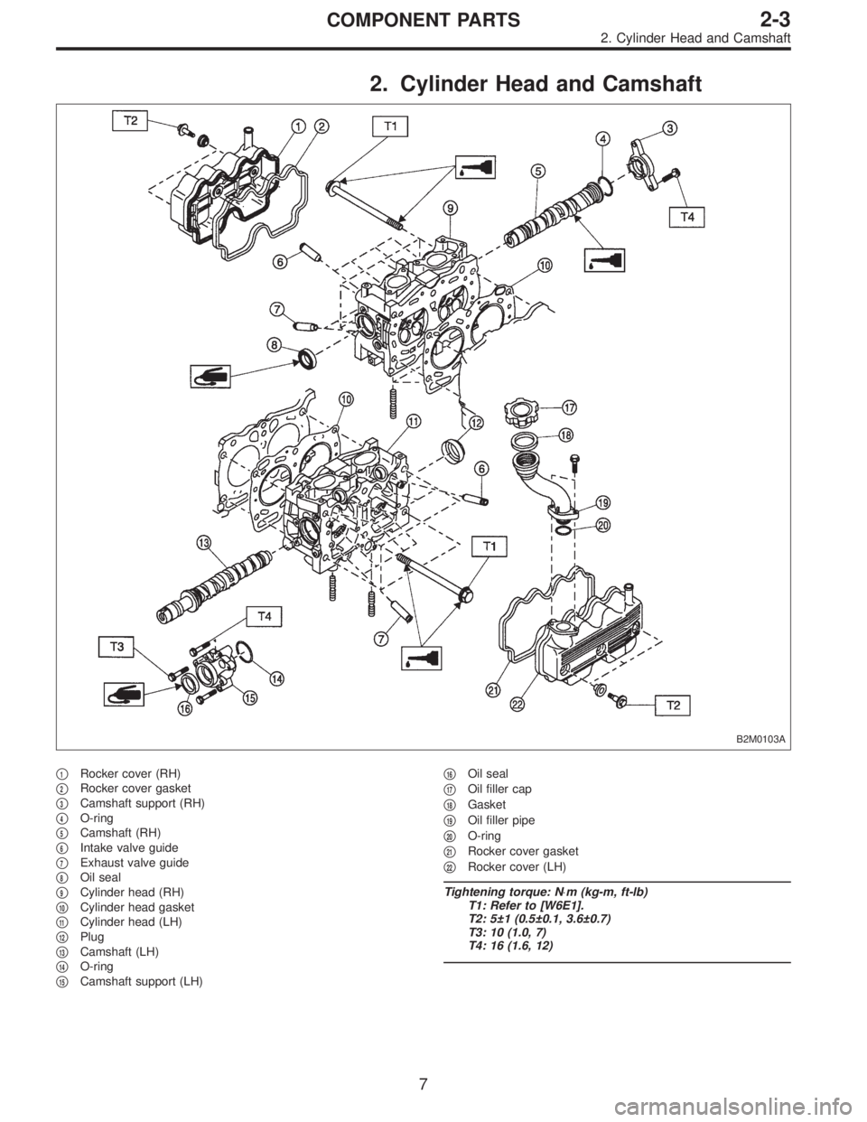
2. Cylinder Head and Camshaft
B2M0103A
�1Rocker cover (RH)
�
2Rocker cover gasket
�
3Camshaft support (RH)
�
4O-ring
�
5Camshaft (RH)
�
6Intake valve guide
�
7Exhaust valve guide
�
8Oil seal
�
9Cylinder head (RH)
�
10Cylinder head gasket
�
11Cylinder head (LH)
�
12Plug
�
13Camshaft (LH)
�
14O-ring
�
15Camshaft support (LH)�
16Oil seal
�
17Oil filler cap
�
18Gasket
�
19Oil filler pipe
�
20O-ring
�
21Rocker cover gasket
�
22Rocker cover (LH)
Tightening torque: N⋅m (kg-m, ft-lb)
T1: Refer to [W6E1].
T2: 5±1 (0.5±0.1, 3.6±0.7)
T3: 10 (1.0, 7)
T4: 16 (1.6, 12)
7
2-3COMPONENT PARTS
2. Cylinder Head and Camshaft
Page 27 of 2248
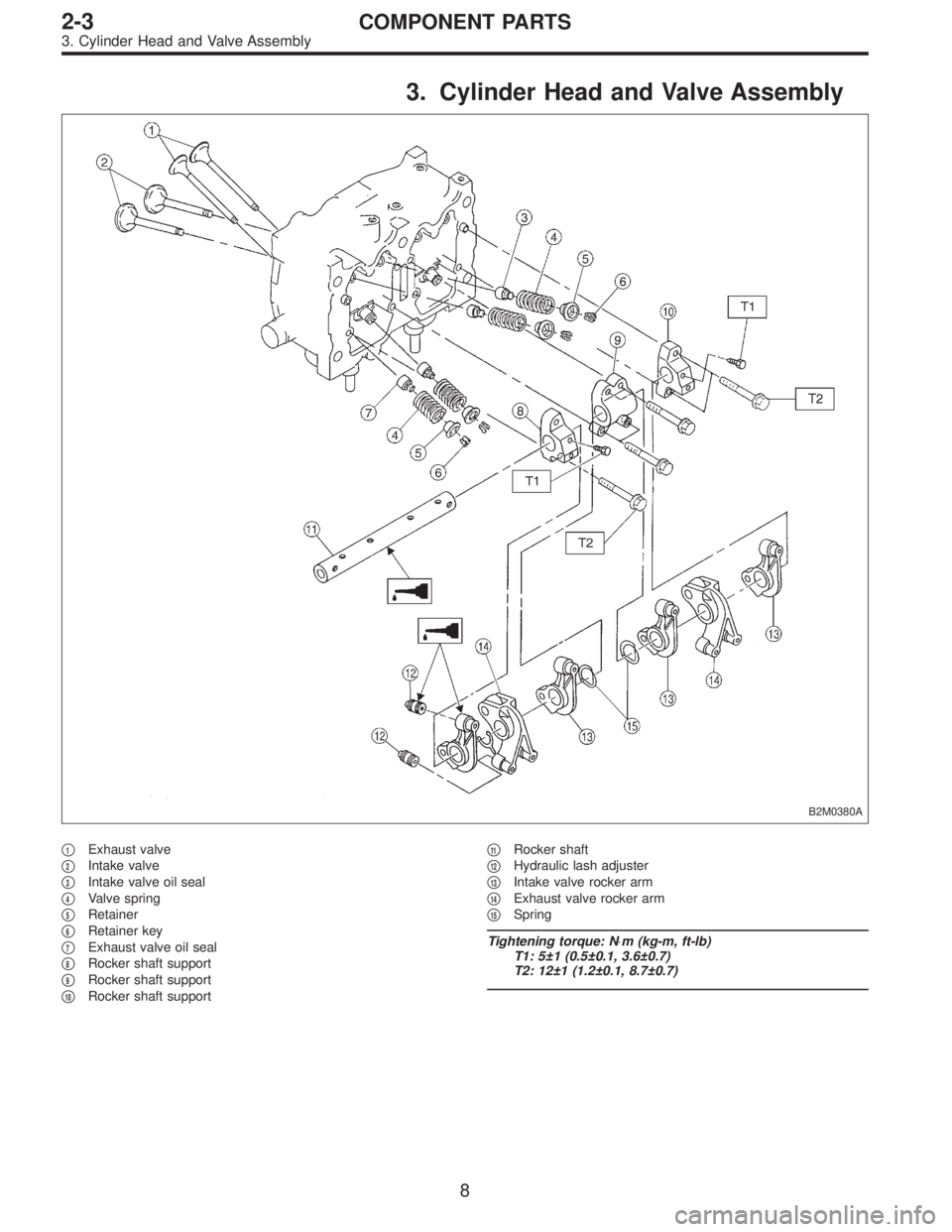
3. Cylinder Head and Valve Assembly
B2M0380A
�1Exhaust valve
�
2Intake valve
�
3Intake valve oil seal
�
4Valve spring
�
5Retainer
�
6Retainer key
�
7Exhaust valve oil seal
�
8Rocker shaft support
�
9Rocker shaft support
�
10Rocker shaft support�
11Rocker shaft
�
12Hydraulic lash adjuster
�
13Intake valve rocker arm
�
14Exhaust valve rocker arm
�
15Spring
Tightening torque: N⋅m (kg-m, ft-lb)
T1: 5±1 (0.5±0.1, 3.6±0.7)
T2: 12±1 (1.2±0.1, 8.7±0.7)
8
2-3COMPONENT PARTS
3. Cylinder Head and Valve Assembly
Page 28 of 2248
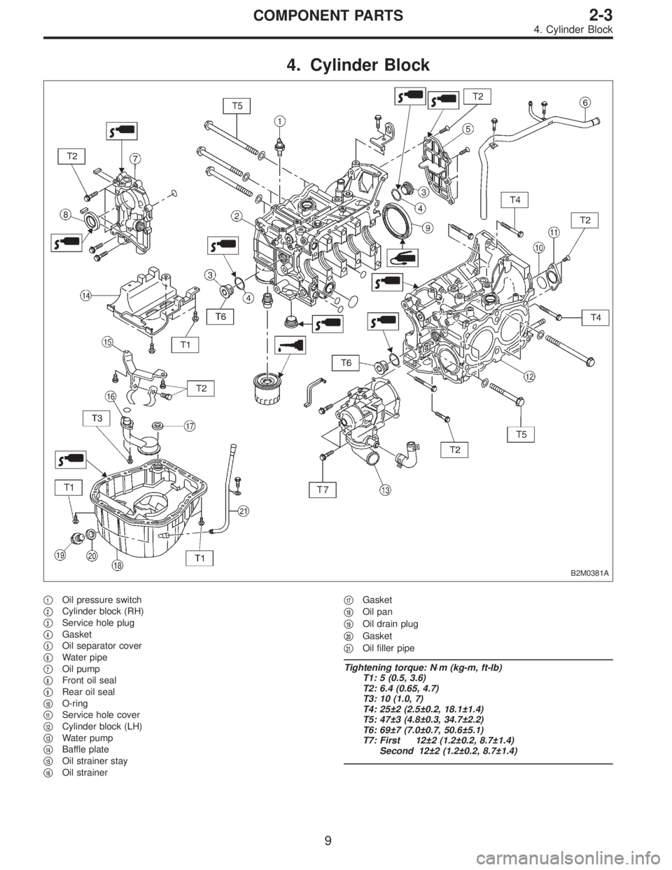
4. Cylinder Block
B2M0381A
�1Oil pressure switch
�
2Cylinder block (RH)
�
3Service hole plug
�
4Gasket
�
5Oil separator cover
�
6Water pipe
�
7Oil pump
�
8Front oil seal
�
9Rear oil seal
�
10O-ring
�
11Service hole cover
�
12Cylinder block (LH)
�
13Water pump
�
14Baffle plate
�
15Oil strainer stay
�
16Oil strainer�
17Gasket
�
18Oil pan
�
19Oil drain plug
�
20Gasket
�
21Oil filler pipe
Tightening torque: N⋅m (kg-m, ft-lb)
T1: 5 (0.5, 3.6)
T2: 6.4 (0.65, 4.7)
T3: 10 (1.0, 7)
T4: 25±2 (2.5±0.2, 18.1±1.4)
T5: 47±3 (4.8±0.3, 34.7±2.2)
T6: 69±7 (7.0±0.7, 50.6±5.1)
T7: First 12±2 (1.2±0.2, 8.7±1.4)
Second 12±2 (1.2±0.2, 8.7±1.4)
9
2-3COMPONENT PARTS
4. Cylinder Block
 Take out purge control solenoid valve through the bot-
tom of the intake manifold.
3) Disconnect connector and hoses from purge control
solenoid valve.
4) Installation is in the reverse ord")
 Take out purge control solenoid valve through the bot-
tom of the intake manifold.
3) Disconnect connector and hoses from purge control
solenoid valve.
4) Installation is in the reverse ord")
 Remove bolt which installs EGR solenoid valve onto
intake manifold.
2) Disconnect hoses and connector from EGR solenoid
valve.
NOTE:
This")
 Connect oil pressure gauge hose to cylinder block.
5) Start the engine, and measure oil pressure.
Oil pressure:
98 kPa (1.0 kg/cm
2,14 psi) or more at 800 rpm
294 kPa (3.0 kg/cm2, 43 psi) o")