Page 1408 of 2248
OBD0145A
5
CHECK MASS AIR FLOW SENSOR.
1) Turn ignition switch to OFF.
2) Connect the Subaru Select Monitor or the OBD-II gen-
eral scan tool to data link connector.
3) Start the engine and warm-up engine until coolant tem-
perature is greater than 60°C (140°F).
OBD0616
4) Read data on Subaru Select Monitor or OBD-II general
scan tool.
�Subaru Select Monitor
Designate mode using function key.
Function mode: F47
�F47: Mass air flow is shown on display.
: Is the voltage within the specifications
shown in the following table?
Engine speed Specified value
Idling 1.9—3.6 (g/sec)
2,500 rpm 7.0—14.8 (g/sec)
: Replace mass air flow sensor.
: Contact with SOA service.
Note: Inspection by DTM is required.
Probable cause: Deterioration of plural parts
�OBD-II general scan tool
For detailed operation procedures, refer to the OBD-II Gen-
eral Scan Tool Instruction Manual.
202
2-7ON-BOARD DIAGNOSTICS II SYSTEM
11. Diagnostics Chart with Trouble Code
Page 1410 of 2248

fuel injector.
�The gallery type fuel injector is installed in the fuel pipe
to allow cooling of the injector by the fuel.")
OBD0265A
DESCRIPTION:
�The MFI system employs a gallery type (side-feed type)
fuel injector.
�The gallery type fuel injector is installed in the fuel pipe
to allow cooling of the injector by the fuel.
�The features of this type of fuel injector are as follows:
1) High heat resistance
2) Low driving noise
3) Easy to service
4) Small size
�The fuel injector injects fuel according to the valve open
signal received from the ECM.
�The nozzle is attached on the top of the fuel injector. The
needle valve is lifted by the solenoid coil through the
plunger on arrival of the valve open signal.
�Since the injection opening, the lifted level of valve and
the regulator-controlled fuel pressure are kept constant,
the amount of fuel to be injected can be controlled only by
the valve open signal from the ECM.
DTC DETECTING CONDITION:
�Immediately at fault recognition
TROUBLE SYMPTOM:
�Failure of engine to start
�Engine stalls.
�Erroneous idling
�Rough driving
204
2-7ON-BOARD DIAGNOSTICS II SYSTEM
11. Diagnostics Chart with Trouble Code
Page 1416 of 2248
OBD0277
U: DTC P0301
—CYLINDER 1 MISFIRE DETECTED (MIS
—1)
—
OBD0278
V: DTC P0302
—CYLINDER 2 MISFIRE DETECTED (MIS
—2)
—
OBD0279
W: DTC P0303
—CYLINDER 3 MISFIRE DETECTED (MIS
—3)
—
OBD0280
X: DTC P0304
—CYLINDER 4 MISFIRE DETECTED (MIS
—4)
—
DTC DETECTING CONDITION:
�Two consecutive trips with fault
�Immediately at fault recognition (A misfire which could
damage catalyst occurs.)
TROUBLE SYMPTOM:
�Engine stalls.
�Erroneous idling
�Rough driving
210
2-7ON-BOARD DIAGNOSTICS II SYSTEM
11. Diagnostics Chart with Trouble Code
Page 1419 of 2248
 Turn ignition switch to OFF.
2) Connect Subaru Select Monitor to the data link connec-
tor.
3) Turn ignition switch to ON, and turn Subaru Sel")
OBD0145A
2CONNECT SUBARU SELECT MONITOR AND
READ DATA.
1) Turn ignition switch to OFF.
2) Connect Subaru Select Monitor to the data link connec-
tor.
3) Turn ignition switch to ON, and turn Subaru Select
Monitor switch to ON.
G3M0152
4) Read data on Subaru Select Monitor.
Designate mode use function key.
Function mode: F33, F34, F35, F36, F37 and F38
NOTE:
F37 and F38 are AT models only.
�F33: Maximum misfire rate of cylinder #1 is indicated.
�F34: Maximum misfire rate of cylinder #2 is indicated.
�F35: Maximum misfire rate of cylinder #3 is indicated.
�F36: Maximum misfire rate of cylinder #4 is indicated.
�F37: Maximum EGR system pressure value is indicated.
�F38: Minimum EGR system pressure value is indicated.
G3M0152
5) Clear memory on Subaru Select Monitor.
Designate mode use function key.
Press [F], [C], [0], [ENT] in that order.
6) Start engine, and drive the vehicle more than 10 min-
utes.
213
2-7ON-BOARD DIAGNOSTICS II SYSTEM
11. Diagnostics Chart with Trouble Code
Page 1420 of 2248
OBD0627
7) Read data on Subaru Select Monitor.
Designate mode use function key.
Function mode: F33, F34, F35 and F36
: Is the maximum misfire rate of each cylin-
der less than 2 %?
: Go to next.
: Go to step 3.
: The vehicle has been empty of fuel.
:�The engine has no abnormality.
�Finish diagnostics operation.
: Go to next.
: Check if the cause of misfire was made
when the engine is running.
Ex. Remove spark plug cord, etc.
:�The engine has no abnormality.
�Finish diagnostics operation.
: Repair poor contact in ignitor, ignition coil, fuel
injector, ECM and coupling harness connector.
3
CHECK AIR INTAKE SYSTEM.
: Check the following items.
�
1Are there air leaks or air suction caused
by loose or dislocated nuts and bolts?
�
2Are there cracks or any disconnection of
hoses?
: Repair air intake system.
: Go to step 4.
214
2-7ON-BOARD DIAGNOSTICS II SYSTEM
11. Diagnostics Chart with Trouble Code
Page 1422 of 2248
�5GROUP OF #2 AND #4 CYLINDERS
: Check the following items for #2 and #4 cyl-
inders.
�Spark plugs
�Fuel injectors
�Skipping timing belt teeth
�
6THE CYLINDER AT RANDOM
: Is the engine idle rough?
: Go to next. (AT models only)
: Go to DTC P0170 [T11P3], [T11P4] and [T11P5].
NOTE:
On MT models, go to DTC P0170 [T11P3], [T11P4] and
[T11P5].
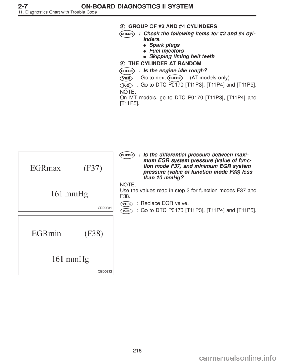
OBD0631
OBD0632
: Is the differential pressure between maxi-
mum EGR system pressure (value of func-
tion mode F37) and minimum EGR system
pressure (value of function mode F38) less
than 10 mmHg?
NOTE:
Use the values read in step 3 for function modes F37 and
F38.
: Replace EGR valve.
: Go to DTC P0170 [T11P3], [T11P4] and [T11P5].
216
2-7ON-BOARD DIAGNOSTICS II SYSTEM
11. Diagnostics Chart with Trouble Code
Page 1423 of 2248
—
OBD0284A
DESCRIPTION:
The knock sensor senses engine knocks and send a volt-
age signal to the ECM depending on the degree of the
kn")
OBD0283
Y: DTC P0325
—KNOCK SENSOR CIRCUIT MALFUNCTION
(KNOCK)—
OBD0284A
DESCRIPTION:
The knock sensor senses engine knocks and send a volt-
age signal to the ECM depending on the degree of the
knock.
This signal information is used for spark timing learning
control to provide optimal spark timing.
The knock sensor is bolted to the cylinder block at #4 pis-
ton. It senses knocks which can occur in any cylinder. Its
components are a weight, which moves up and down when
it senses vibrations, a piezo element, which produces a
voltage, and a resistor, which senses a broken circuit (all
these are molded into a single unit). When the sensor
senses engine knocks, knocking vibration is conveyed to
the weight. The up or down movement of the weight is
applied to the piezo element as a pressure difference. The
knock sensor will then produce a voltage signal in relation
to the degree of the knock.
DTC DETECTING CONDITION:
�Immediately at fault recognition
TROUBLE SYMPTOM:
�Poor driving performance
�Knocking occurs.
217
2-7ON-BOARD DIAGNOSTICS II SYSTEM
11. Diagnostics Chart with Trouble Code
Page 1428 of 2248
DTC DETECTING CONDITION:
�Immediately at fault recognition
TROUBLE SYMPTOM:
�Engine stalls.
�Failure of engine to start
1.Check harness.
2.Check crankshaft position sensor.
CAUTION:
After repair or replacement of faulty parts, conduct
CLEAR MEMORY and INSPECTION MODES.
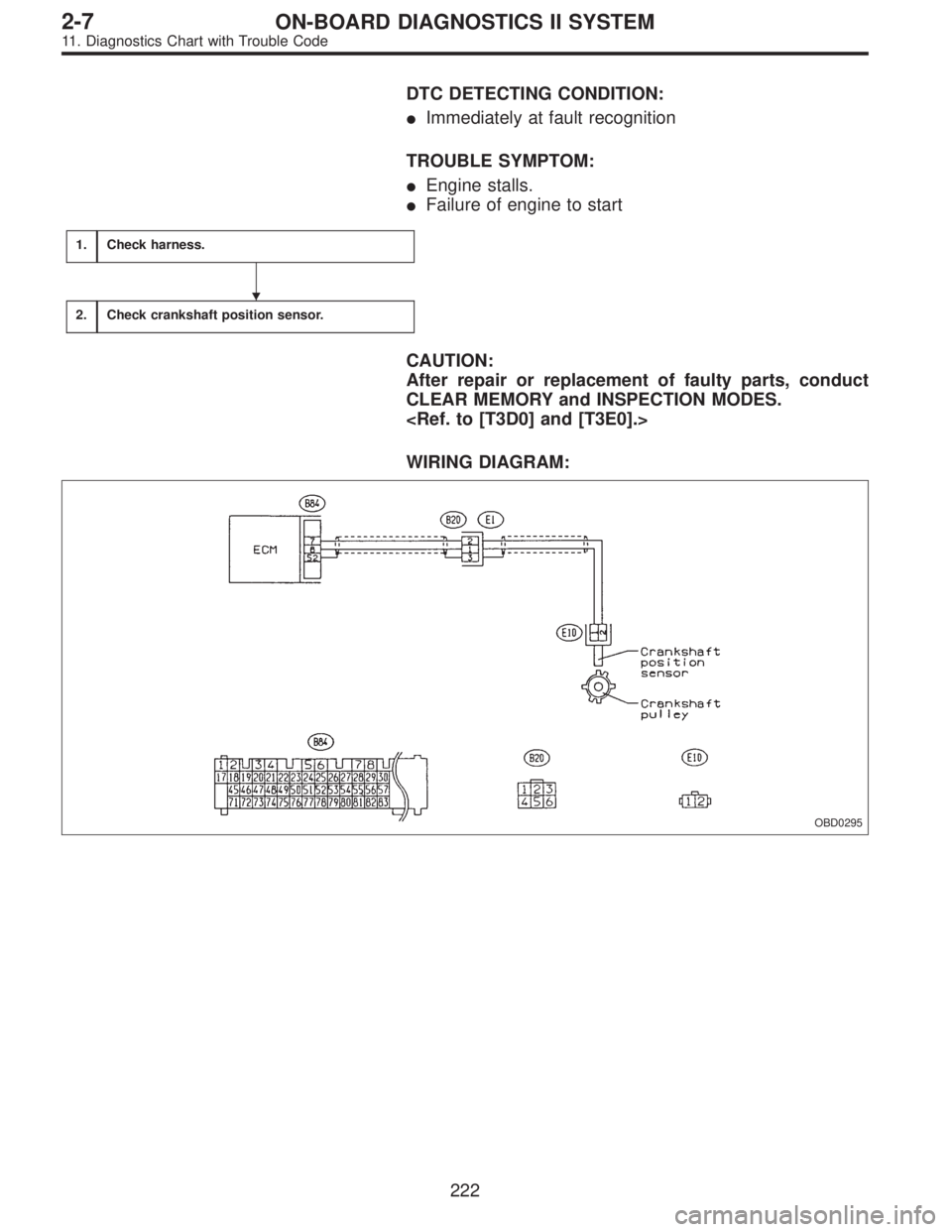
WIRING DIAGRAM:
OBD0295
�
222
2-7ON-BOARD DIAGNOSTICS II SYSTEM
11. Diagnostics Chart with Trouble Code
 Turn ignition switch to OFF.
2) Connect the Subaru Select Monitor or the OBD-II gen-
eral scan tool to data link connector.
3) Start the engine and warm-up en")

—
OBD0278
V: DTC P0302
—CYLINDER 2 MISFIRE DETECTED (MIS
—2)
—
OBD0279
W: DTC P0303
—CYLINDER 3 MISFIRE DETECTED (MIS
—3)
—")
 Read data on Subaru Select Monitor.
Designate mode use function key.
Function mode: F33, F34, F35 and F36
: Is the maximum misfire rate of each cylin-
der less than 2 %?
: Go to next.
: Go")