Page 1431 of 2248
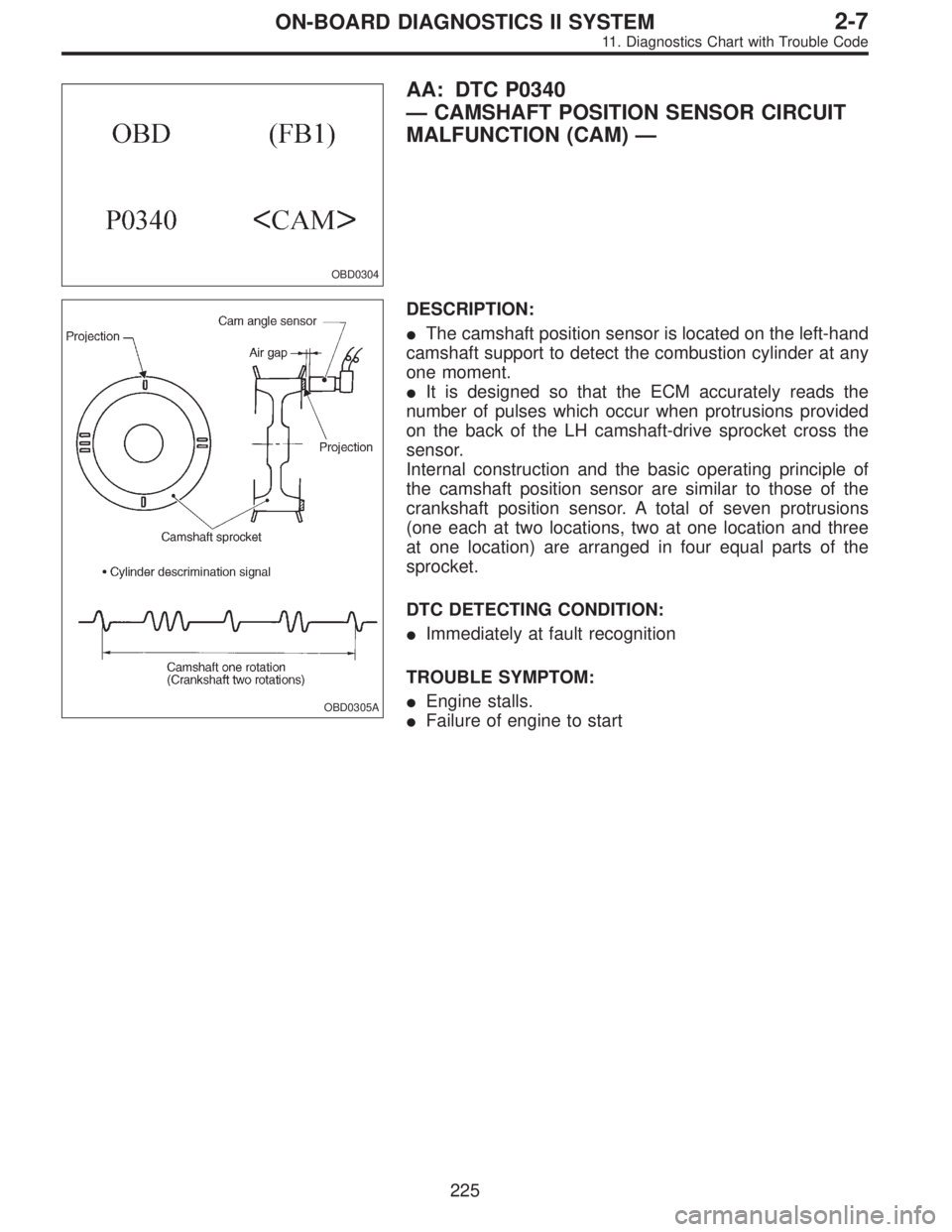
OBD0304
AA: DTC P0340
—CAMSHAFT POSITION SENSOR CIRCUIT
MALFUNCTION (CAM)—
OBD0305A
DESCRIPTION:
�The camshaft position sensor is located on the left-hand
camshaft support to detect the combustion cylinder at any
one moment.
�It is designed so that the ECM accurately reads the
number of pulses which occur when protrusions provided
on the back of the LH camshaft-drive sprocket cross the
sensor.
Internal construction and the basic operating principle of
the camshaft position sensor are similar to those of the
crankshaft position sensor. A total of seven protrusions
(one each at two locations, two at one location and three
at one location) are arranged in four equal parts of the
sprocket.
DTC DETECTING CONDITION:
�Immediately at fault recognition
TROUBLE SYMPTOM:
�Engine stalls.
�Failure of engine to start
225
2-7ON-BOARD DIAGNOSTICS II SYSTEM
11. Diagnostics Chart with Trouble Code
Page 1435 of 2248
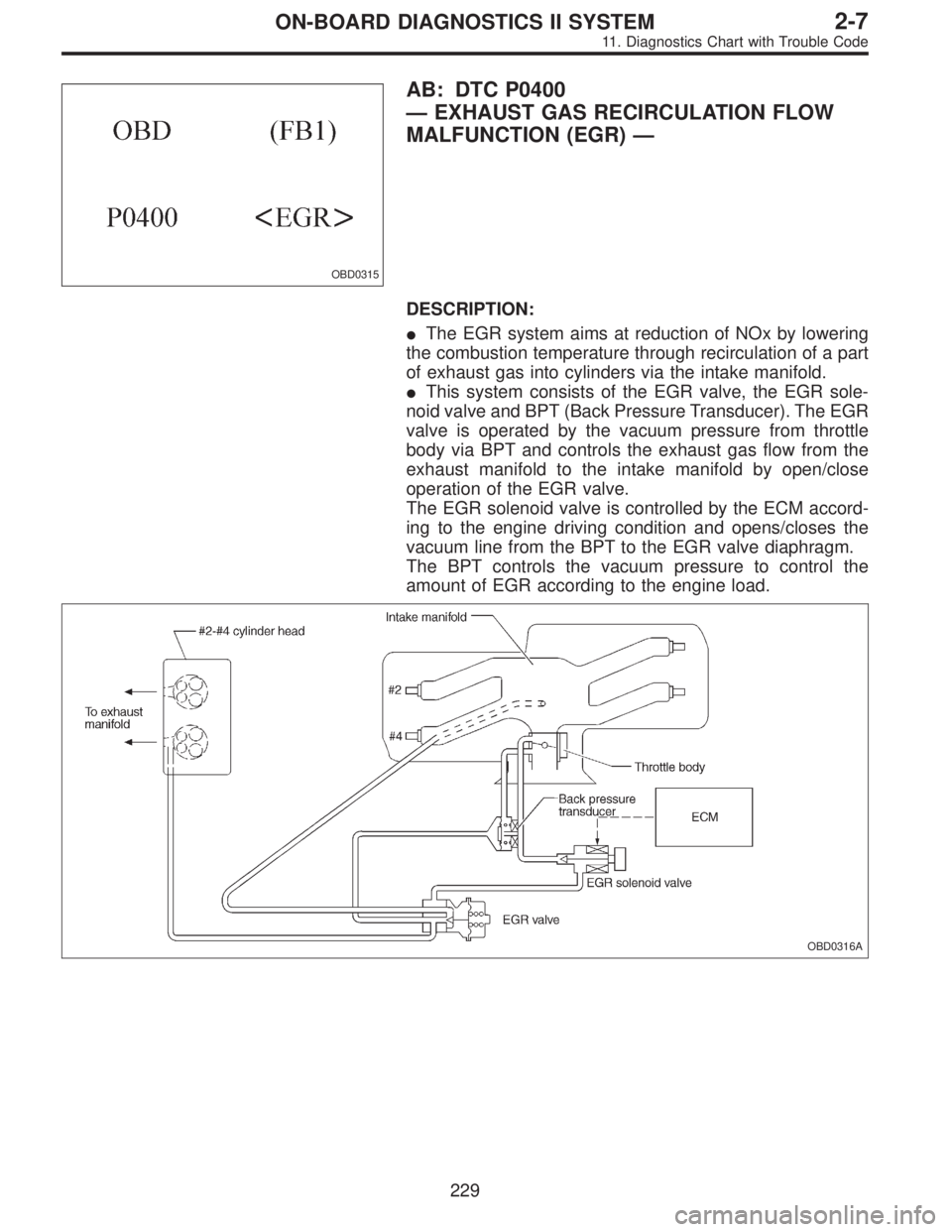
OBD0315
AB: DTC P0400
—EXHAUST GAS RECIRCULATION FLOW
MALFUNCTION (EGR)—
DESCRIPTION:
�The EGR system aims at reduction of NOx by lowering
the combustion temperature through recirculation of a part
of exhaust gas into cylinders via the intake manifold.
�This system consists of the EGR valve, the EGR sole-
noid valve and BPT (Back Pressure Transducer). The EGR
valve is operated by the vacuum pressure from throttle
body via BPT and controls the exhaust gas flow from the
exhaust manifold to the intake manifold by open/close
operation of the EGR valve.
The EGR solenoid valve is controlled by the ECM accord-
ing to the engine driving condition and opens/closes the
vacuum line from the BPT to the EGR valve diaphragm.
The BPT controls the vacuum pressure to control the
amount of EGR according to the engine load.
OBD0316A
229
2-7ON-BOARD DIAGNOSTICS II SYSTEM
11. Diagnostics Chart with Trouble Code
Page 1436 of 2248
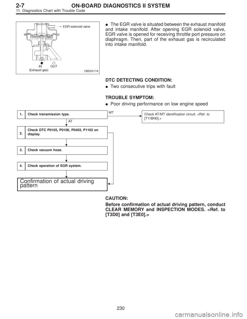
OBD0317A
�The EGR valve is situated between the exhaust manifold
and intake manifold. After opening EGR solenoid valve,
EGR valve is opened for receiving throttle port pressure on
diaphragm. Then, part of the exhaust gas is recirculated
into intake manifold.
DTC DETECTING CONDITION:
�Two consecutive trips with fault
TROUBLE SYMPTOM:
�Poor driving performance on low engine speed
1.Check transmission type.
AT
�MT
Check AT/MT identification circuit.
[T11BN0].>
2.Check DTC P0105, P0106, P0403, P1102 on
display.
�
3.Check vacuum hose.
4.Check operation of EGR system.
Confirmation of actual driving
pattern
CAUTION:
Before confirmation of actual driving pattern, conduct
CLEAR MEMORY and INSPECTION MODES.
[T3D0] and [T3E0].>
�
�
�
�
230
2-7ON-BOARD DIAGNOSTICS II SYSTEM
11. Diagnostics Chart with Trouble Code
Page 1439 of 2248

3
CHECK VACUUM HOSE.
: Check vacuum hoses for disconnection,
leakage and clogging.
: Check and repair the following items.
�Two lines of pipes and hoses running between
throttle body and BPT
�Pipe and hose line connecting BPT and EGR
solenoid valve
�Hose between EGR solenoid valve and EGR
valve
�BPT pressure transmitting hose
: Go to step 4.
4
CHECK OPERATION OF EGR SYSTEM.
1) Turn ignition switch to OFF.
2) Connect the test mode connector.
3) Turn ignition switch to ON.
: Does EGR solenoid valve produce operating
sound?
: Replace EGR solenoid valve.
: Go to next step.
4) Turn ignition switch to OFF.
5) Disconnect connector from EGR solenoid valve.
6) Connect 12 V battery’s ground�terminal to one ter-
minal of the EGR solenoid valve. Then connect 12 V bat-
tery’s�terminal to the other terminal of it.
CAUTION:
Do not use the 12 V battery installed in the vehicle,
because the electrical system may be damaged.
7) Start the engine.
: Open throttle valve by 5 to 10 degrees and
visually check EGR valve operation.
: Possibly EGR valve malfunction may be due to
freezing or clogging by foreign matter. At this point
in time do not replace EGR valve, since it is not
faulty. And after the checking, go to
CONFIR-
MATION OF ACTUAL DRIVING PATTERN.
NOTE:
If malfunction is detected again in the confirmation of actual
driving pattern, EGR valve is faulty. Go to next
.
: Go to next.
233
2-7ON-BOARD DIAGNOSTICS II SYSTEM
11. Diagnostics Chart with Trouble Code
Page 1440 of 2248

: Is there clogging in the gas outlets of intake
manifold or cylinder head, checking by
breathing into the outlets?
: Repair or replace intake manifold or cylinder
head. And go to
CONFIRMATION OF
ACTUAL DRIVING PATTERN.
: Replace EGR valve. And go toCONFIRMA-
TION OF ACTUAL DRIVING PATTERN.
CONFIRMATION OF ACTUAL DRIVING
PATTERN.
1) Conduct CLEAR MEMORY and INSPECTION MODES.
2) Connect Subaru select monitor to its data link connec-
tor.
3) Start and warm-up the engine until the radiator fan
makes one complete rotation. (All accessory switches are
OFF.)
4) Turn Subaru select monitor switch to ON.
5) Designate mode using function key.
Function mode: FA4
6) Drive at 55±3 MPH (88±5 km/h) until the LED No. 5 is
turned on.
NOTE:
Keep the throttle valve opening at the same degree, since
diagnosis will be interrupted when the opening varies.
Diagnosis starts in 190 seconds after starting engine and
takes 4 seconds.
Put the gear to“D”range for the diagnosis.
7) Designate mode using function key.
Function mode: FB0
8) Confirm the“No trouble”indication on Subaru select
monitor.
234
2-7ON-BOARD DIAGNOSTICS II SYSTEM
11. Diagnostics Chart with Trouble Code
Page 1441 of 2248
OBD0323
AC: DTC P0403
—EXHAUST GAS RECIRCULATION CIRCUIT
MALFUNCTION (EGRSOL)—
OBD0324A
DESCRIPTION:
The EGR solenoid valve is situated between the BPT and
EGR valve. EGR solenoid valve is opened by a signal
emitted from the ECM. Therefore, throttle port pressure is
transmitted to diaphragm of EGR valve.
DTC DETECTING CONDITION:
�Two consecutive trips with fault
TROUBLE SYMPTOM:
�Poor driving performance on low engine speed
1.Check transmission type.
AT
�MT
Check AT/MT identification circuit.
2.Check output signal from ECM.
�
3.Check harness.
4.Check harness.
5.Check EGR solenoid valve.
6.Check power supply to EGR solenoid valve.
CAUTION:
After repair or replacement of faulty parts, conduct
CLEAR MEMORY and INSPECTION MODES.
[T3D0] and [T3E0].>
�
�
�
�
235
2-7ON-BOARD DIAGNOSTICS II SYSTEM
11. Diagnostics Chart with Trouble Code
Page 1446 of 2248
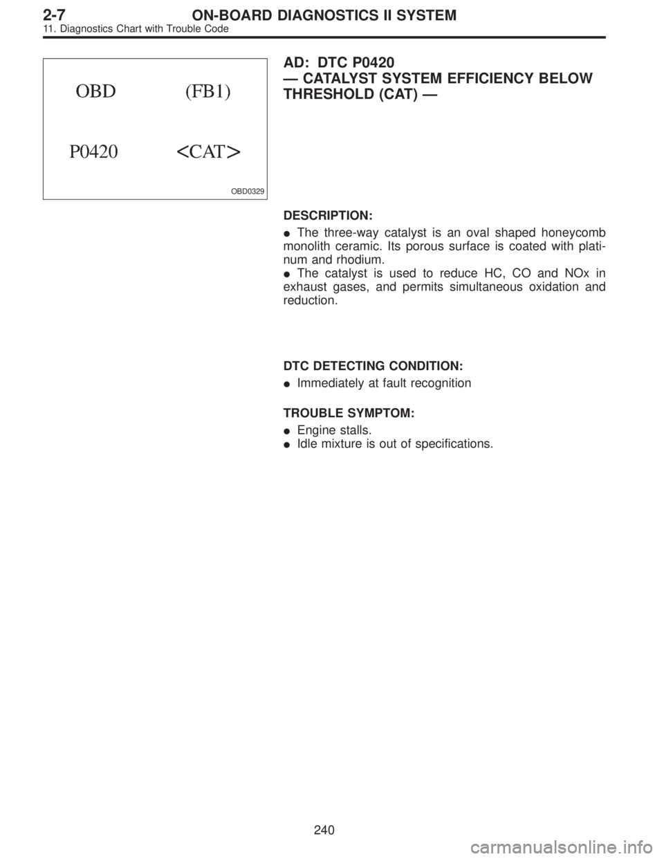
OBD0329
AD: DTC P0420
—CATALYST SYSTEM EFFICIENCY BELOW
THRESHOLD (CAT)—
DESCRIPTION:
�The three-way catalyst is an oval shaped honeycomb
monolith ceramic. Its porous surface is coated with plati-
num and rhodium.
�The catalyst is used to reduce HC, CO and NOx in
exhaust gases, and permits simultaneous oxidation and
reduction.
DTC DETECTING CONDITION:
�Immediately at fault recognition
TROUBLE SYMPTOM:
�Engine stalls.
�Idle mixture is out of specifications.
240
2-7ON-BOARD DIAGNOSTICS II SYSTEM
11. Diagnostics Chart with Trouble Code
Page 1450 of 2248
OBD0331
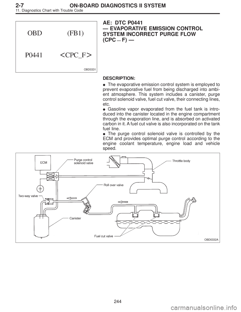
AE: DTC P0441
—EVAPORATIVE EMISSION CONTROL
SYSTEM INCORRECT PURGE FLOW
(CPC
—F)—
DESCRIPTION:
�The evaporative emission control system is employed to
prevent evaporative fuel from being discharged into ambi-
ent atmosphere. This system includes a canister, purge
control solenoid valve, fuel cut valve, their connecting lines,
etc.
�Gasoline vapor evaporated from the fuel tank is intro-
duced into the canister located in the engine compartment
through the evaporation line, and is absorbed on activated
carbon in it. A fuel cut valve is also incorporated on the tank
fuel line.
�The purge control solenoid valve is controlled by the
ECM and provides optimal purge control according to the
engine coolant temperature, engine load and vehicle
speed.
OBD0332A
244
2-7ON-BOARD DIAGNOSTICS II SYSTEM
11. Diagnostics Chart with Trouble Code
—
OBD0324A
DESCRIPTION:
The EGR solenoid valve is situated between the BPT and
EGR valve. EGR solenoid valve is opened")