Page 1500 of 2248
OBD0411
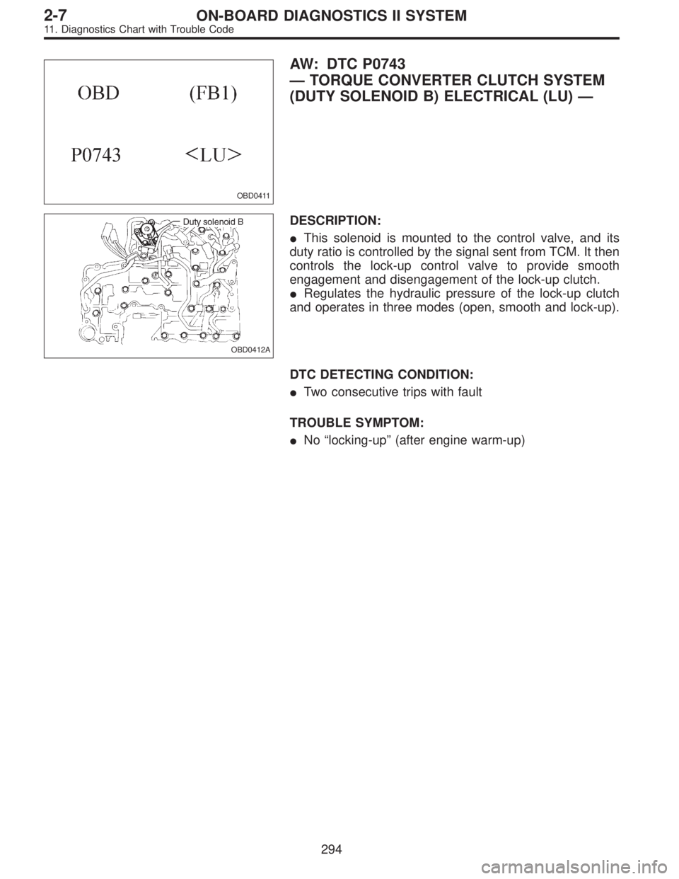
AW: DTC P0743
—TORQUE CONVERTER CLUTCH SYSTEM
(DUTY SOLENOID B) ELECTRICAL (LU)—
OBD0412A
DESCRIPTION:
�This solenoid is mounted to the control valve, and its
duty ratio is controlled by the signal sent from TCM. It then
controls the lock-up control valve to provide smooth
engagement and disengagement of the lock-up clutch.
�Regulates the hydraulic pressure of the lock-up clutch
and operates in three modes (open, smooth and lock-up).
DTC DETECTING CONDITION:
�Two consecutive trips with fault
TROUBLE SYMPTOM:
�No“locking-up”(after engine warm-up)
294
2-7ON-BOARD DIAGNOSTICS II SYSTEM
11. Diagnostics Chart with Trouble Code
Page 1508 of 2248
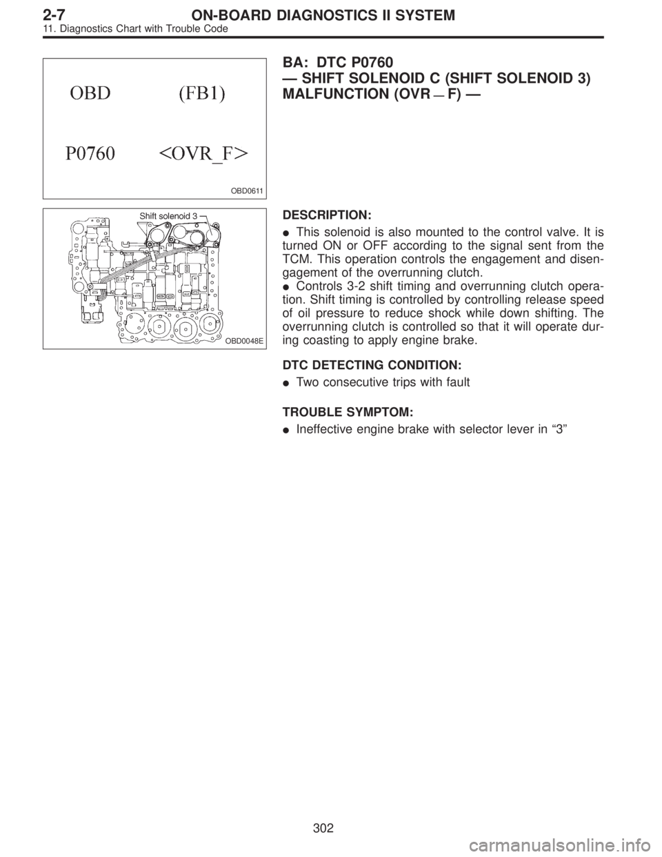
OBD0611
BA: DTC P0760
—SHIFT SOLENOID C (SHIFT SOLENOID 3)
MALFUNCTION (OVR
—F)—
OBD0048E
DESCRIPTION:
�This solenoid is also mounted to the control valve. It is
turned ON or OFF according to the signal sent from the
TCM. This operation controls the engagement and disen-
gagement of the overrunning clutch.
�Controls 3-2 shift timing and overrunning clutch opera-
tion. Shift timing is controlled by controlling release speed
of oil pressure to reduce shock while down shifting. The
overrunning clutch is controlled so that it will operate dur-
ing coasting to apply engine brake.
DTC DETECTING CONDITION:
�Two consecutive trips with fault
TROUBLE SYMPTOM:
�Ineffective engine brake with selector lever in“3”
302
2-7ON-BOARD DIAGNOSTICS II SYSTEM
11. Diagnostics Chart with Trouble Code
Page 1511 of 2248
 Lift-up or raise the vehicle and support with safety
stands.
CAUTION:
On AWD models, raise all wheels off ground.
4) Start and warm-up the engine and transmission.
5) Subaru select monitor")
OBD0615
3) Lift-up or raise the vehicle and support with safety
stands.
CAUTION:
On AWD models, raise all wheels off ground.
4) Start and warm-up the engine and transmission.
5) Subaru select monitor switch to ON.
6) Designate mode using function key.
Function mode for AT: F10
7) Move selector lever to“D”and drive the vehicle.
8) Read data on Subaru select monitor.
: Change gear position according to throttle
position and vehicle speed.
: Go to next.
: Go to step 4.
: Is there poor contact in TCM connector?
: Repair poor contact in TCM connector.
: Go to next.
: Is there any mechanical trouble in automatic
transmission?
: Repair or replace automatic transmission.
: Replace TCM with a new one.
4
CHECK SHIFT SOLENOID 1 CIRCUIT.
: Is there any trouble in shift solenoid 1 cir-
cuit?
: Repair or replace shift solenoid 1 circuit.
: Go to step 5.
5
CHECK SHIFT SOLENOID 2 CIRCUIT.
: Is there any trouble in shift solenoid 2 cir-
cuit?
: Repair or replace shift solenoid 2 circuit.
: Go to step 6.
305
2-7ON-BOARD DIAGNOSTICS II SYSTEM
11. Diagnostics Chart with Trouble Code
Page 1513 of 2248
OBD0450
BB: DTC P0763
—SHIFT SOLENOID C (SHIFT SOLENOID 3)
ELECTRICAL (OVR)—
DESCRIPTION:
Refer to“BA: DTC P0760—SHIFT SOLENOID C MAL-
FUNCTION—[T11BA0]”.
DTC DETECTING CONDITION:
�Two consecutive trips with fault
TROUBLE SYMPTOM:
�Ineffective engine brake with selector lever in“3”
307
2-7ON-BOARD DIAGNOSTICS II SYSTEM
11. Diagnostics Chart with Trouble Code
Page 1515 of 2248
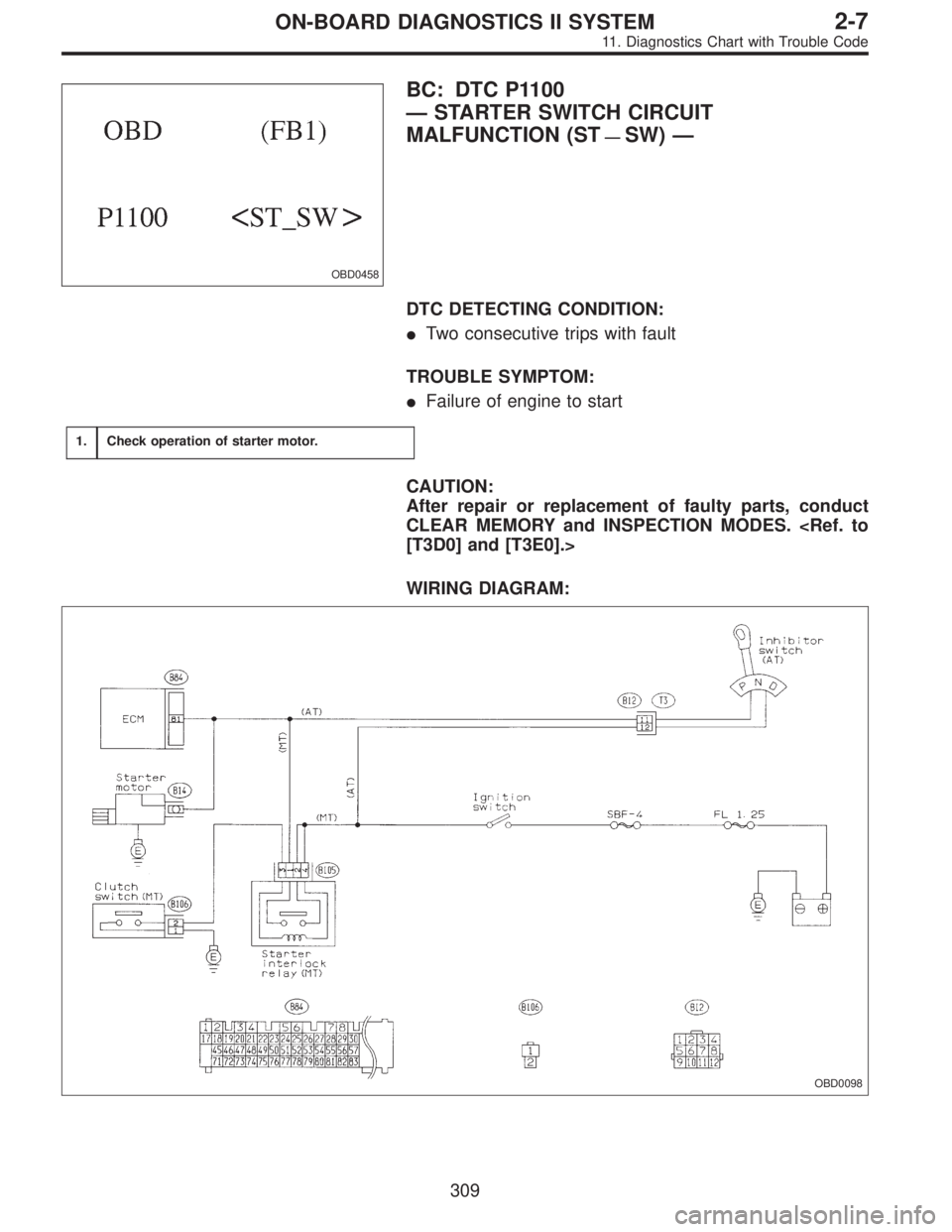
OBD0458
BC: DTC P1100
—STARTER SWITCH CIRCUIT
MALFUNCTION (ST
—SW)—
DTC DETECTING CONDITION:
�Two consecutive trips with fault
TROUBLE SYMPTOM:
�Failure of engine to start
1.Check operation of starter motor.
CAUTION:
After repair or replacement of faulty parts, conduct
CLEAR MEMORY and INSPECTION MODES.
[T3D0] and [T3E0].>
WIRING DIAGRAM:
OBD0098
309
2-7ON-BOARD DIAGNOSTICS II SYSTEM
11. Diagnostics Chart with Trouble Code
Page 1525 of 2248
OBD0481
BF: DTC P1102
—PRESSURE SOURCES SWITCHING
SOLENOID VALVE CIRCUIT MALFUNCTION
(BR)—
DESCRIPTION:
Refer to“D: DTC P0105—PRESSURE SENSOR CIR-
CUIT MALFUNCTION—[T11D0]”.
DTC DETECTING CONDITION:
�Two consecutive trips with fault
TROUBLE SYMPTOM:
�Erroneous idling
�Failure of engine to start
319
2-7ON-BOARD DIAGNOSTICS II SYSTEM
11. Diagnostics Chart with Trouble Code
Page 1531 of 2248
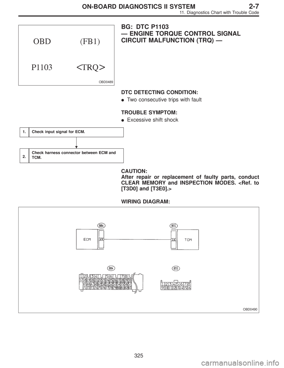
OBD0489
BG: DTC P1103
—ENGINE TORQUE CONTROL SIGNAL
CIRCUIT MALFUNCTION (TRQ)—
DTC DETECTING CONDITION:
�Two consecutive trips with fault
TROUBLE SYMPTOM:
�Excessive shift shock
1.Check input signal for ECM.
2.Check harness connector between ECM and
TCM.
CAUTION:
After repair or replacement of faulty parts, conduct
CLEAR MEMORY and INSPECTION MODES.
[T3D0] and [T3E0].>
WIRING DIAGRAM:
OBD0490
�
325
2-7ON-BOARD DIAGNOSTICS II SYSTEM
11. Diagnostics Chart with Trouble Code
Page 1537 of 2248
—
DESCRIPTION:
�The engine cooling system consists of a down-flow
radiator which features high heat-dissipation performanc")
OBD0527
BI: DTC P1500
—RADIATOR FAN RELAY 1 CIRCUIT
MALFUNCTION (FAN
—1)—
DESCRIPTION:
�The engine cooling system consists of a down-flow
radiator which features high heat-dissipation performance,
an electric motor fan, an engine coolant pump, a
thermostat, and an engine coolant temperature sensor.
�The ON-OFF control of the radiator fan is governed by
the ECM which receives signals sent from the engine cool-
ant temperature sensor. On models which are equipped
with an air conditioning system, the ECM receives signals
sent from the engine coolant temperature sensor, vehicle
speed sensor 2 and A/C switch. These signals simulta-
neously turn ON or OFF the radiator main fan and radiator
sub fan as well as setting them at“HI”or“LO”speed.
[Without A/C models]
Engine coolant temperature signal *1ECM output signal Operation of radiator fan
Radiator fan relay 1 Main
ON ON ON
OFF OFF OFF
*1 ON: Above 95°C (203°F), OFF: Below 89°C (192°F)
[With A/C models]
Engine coolant
temperature
signal *2A/C compressorVehicle speed
signal *3ECM output signal Operation of radiator fan
Radiator fan
relay 1Radiator fan
relay 2Main Sub
ONONON ON ON HI HI
OFF ON ON HI HI
OFFON ON ON HI HI
OFF ON OFF LO LO
OFFONON ON ON HI HI
OFF ON OFF LO LO
OFFON OFF OFF OFF OFF
OFF OFF OFF OFF OFF
*2 ON: Above 95°C (203°F), OFF: Below 89°C (192°F)
*3 ON: Above 20 km/h (12 MPH), OFF: Below 10 km/h (6 MPH)
331
2-7ON-BOARD DIAGNOSTICS II SYSTEM
11. Diagnostics Chart with Trouble Code

![SUBARU LEGACY 1995 Service Repair Manual OBD0481
BF: DTC P1102
—PRESSURE SOURCES SWITCHING
SOLENOID VALVE CIRCUIT MALFUNCTION
(BR)—
DESCRIPTION:
Refer to“D: DTC P0105—PRESSURE SENSOR CIR-
CUIT MALFUNCTION—[T11D0]”.
DTC DETECTING](/manual-img/17/57432/w960_57432-1524.png "SUBARU LEGACY 1995 Service Repair Manual OBD0481
BF: DTC P1102
—PRESSURE SOURCES SWITCHING
SOLENOID VALVE CIRCUIT MALFUNCTION
(BR)—
DESCRIPTION:
Refer to“D: DTC P0105—PRESSURE SENSOR CIR-
CUIT MALFUNCTION—[T11D0]”.
DTC DETECTING")