Page 1546 of 2248
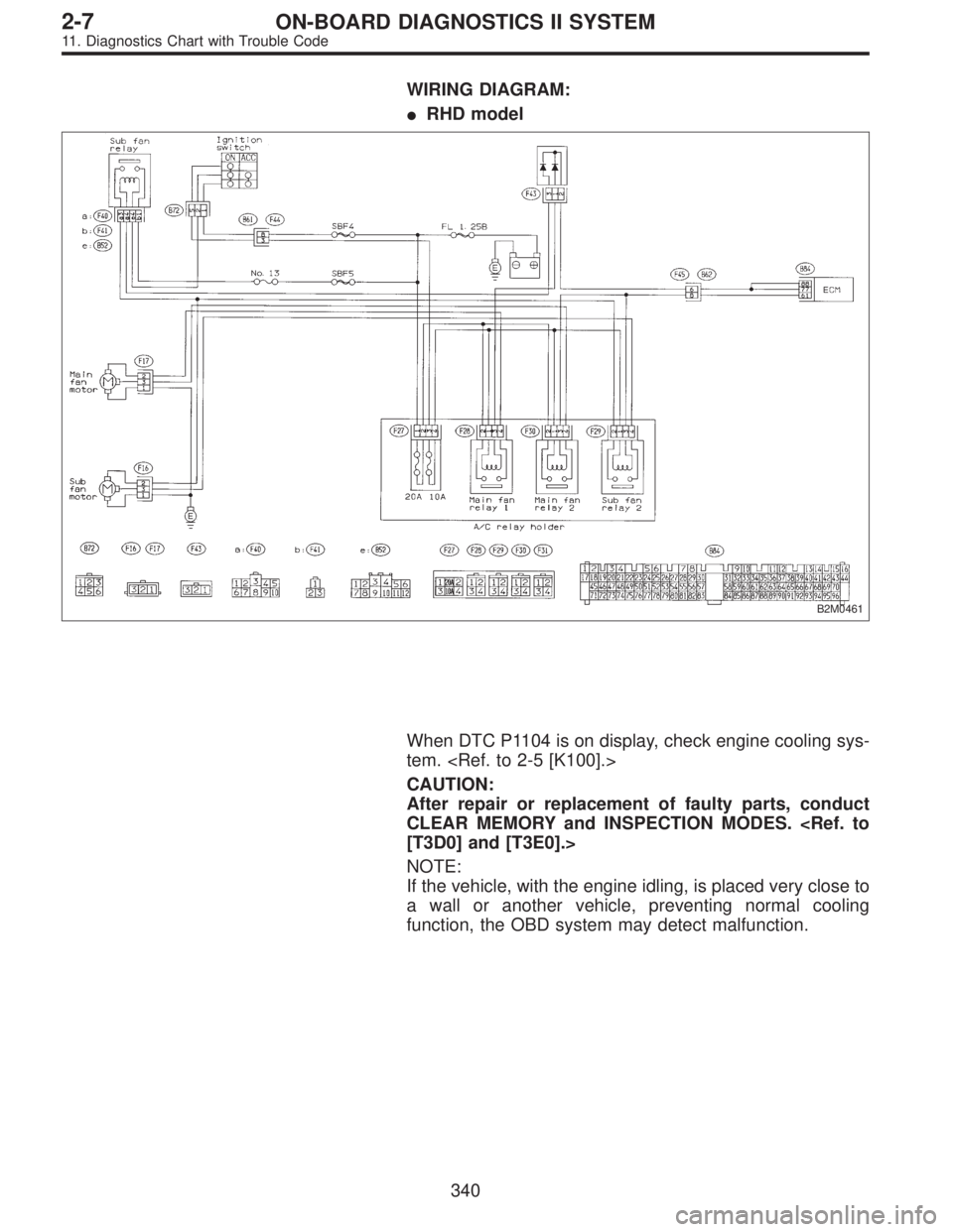
WIRING DIAGRAM:
�RHD model
B2M0461
When DTC P1104 is on display, check engine cooling sys-
tem.
CAUTION:
After repair or replacement of faulty parts, conduct
CLEAR MEMORY and INSPECTION MODES.
[T3D0] and [T3E0].>
NOTE:
If the vehicle, with the engine idling, is placed very close to
a wall or another vehicle, preventing normal cooling
function, the OBD system may detect malfunction.
340
2-7ON-BOARD DIAGNOSTICS II SYSTEM
11. Diagnostics Chart with Trouble Code
Page 1547 of 2248
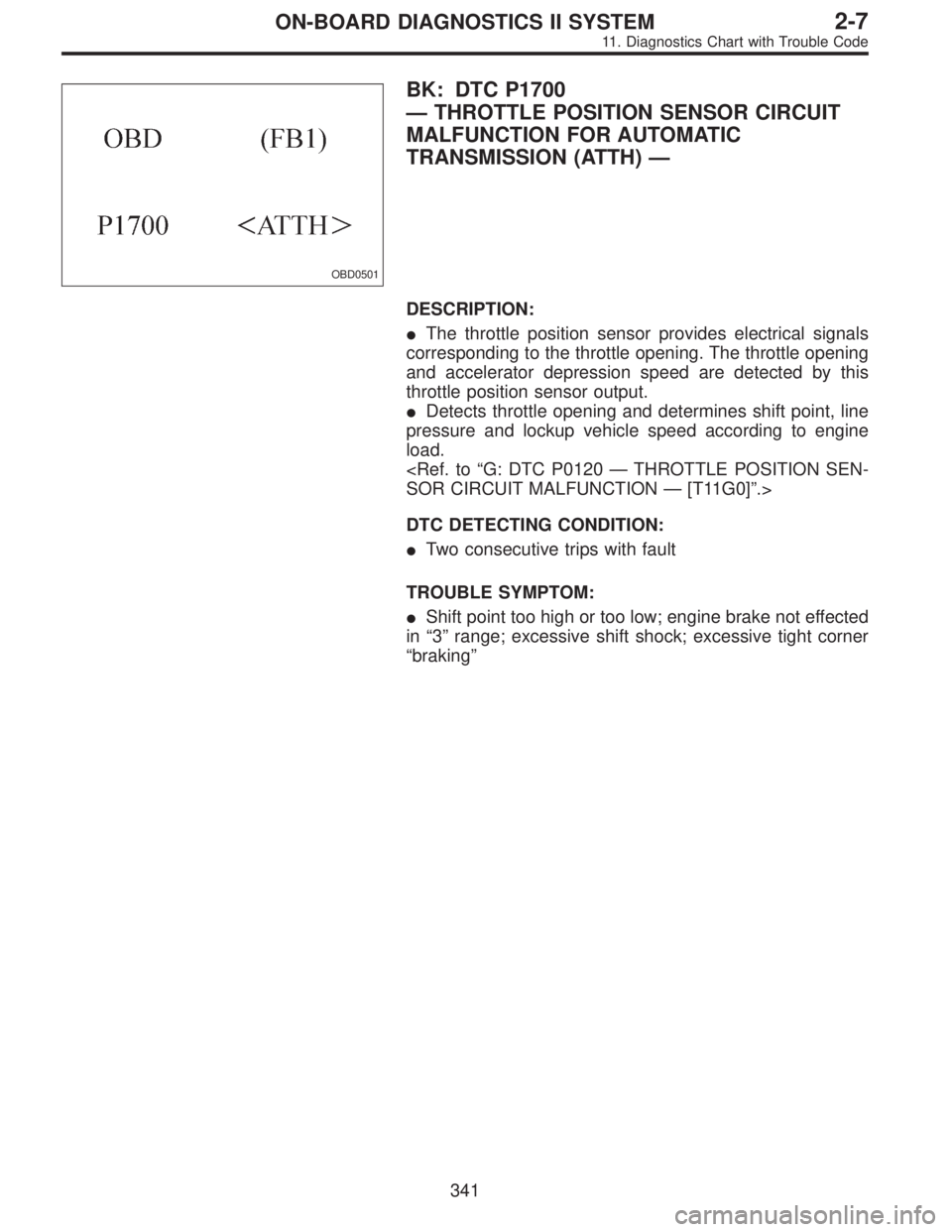
OBD0501
BK: DTC P1700
—THROTTLE POSITION SENSOR CIRCUIT
MALFUNCTION FOR AUTOMATIC
TRANSMISSION (ATTH)—
DESCRIPTION:
�The throttle position sensor provides electrical signals
corresponding to the throttle opening. The throttle opening
and accelerator depression speed are detected by this
throttle position sensor output.
�Detects throttle opening and determines shift point, line
pressure and lockup vehicle speed according to engine
load.
SOR CIRCUIT MALFUNCTION—[T11G0]”.>
DTC DETECTING CONDITION:
�Two consecutive trips with fault
TROUBLE SYMPTOM:
�Shift point too high or too low; engine brake not effected
in“3”range; excessive shift shock; excessive tight corner
“braking”
341
2-7ON-BOARD DIAGNOSTICS II SYSTEM
11. Diagnostics Chart with Trouble Code
Page 1551 of 2248
OBD0513A
2
CHECK INPUT SIGNAL FOR TCM.
1) Connect connector to TCM and CCM.
2) Lift-up the vehicle or set the vehicle on free rollers.
CAUTION:
On AWD models, raise all wheels off ground.
3) Start the engine.
4) Cruise control main switch to ON.
5) TCS OFF switch to ON. (with TCS models only)
6) Move selector lever to“D”and slowly increase vehicle
speed to 50 km/h (31 MPH).
7) Cruise control set switch to ON.
8) Measure voltage between TCM and body.
: Connector & terminal
(B56) No. 3—Body / 1 V, or less
: Check cruise control set circuit.
[T7A0].>
: Go to next.
: Is there poor contact in TCM connector?
: Repair poor contact in TCM connector.
: Replace TCM with a new one.
345
2-7ON-BOARD DIAGNOSTICS II SYSTEM
11. Diagnostics Chart with Trouble Code
Page 1557 of 2248
 Check that selector lever does not move from“N”to“R”
without pushing the bu")
G3M0717
3. OPERATION OF SHIFT SELECTOR LEVER
WARNING:
Stop the engine while checking operation of selector
lever.
1) Check that selector lever does not move from“N”to“R”
without pushing the button.
2) Check that selector lever does not move from“R”to“P”
without pushing the button.
3) Check that selector lever does not move from“P”to“R”
without pushing the button.
4) Check that selector lever does not move from“3”to“2”
without pushing the button.
3. Electrical Components Location
1. SENSOR AND CONTROL MODULE
B3M0178B
�1Throttle position sensor
�
2Dropping resistor
�
3Vehicle speed sensor 2
�
4Inhibitor switch
�
5ECM
�
6Vehicle speed sensor 1 (AWD)
�
7Vehicle speed sensor 1 (FWD)
�
8TCM�
9Data link connector (for Subaru select monitor only)
�
10Data link connector (for Subaru select monitor and OBD-II
general scan tool)
�
11Diagnosis connector
�
12Diagnosis terminal
�
13AT OIL TEMP indicator light
(AT diagnostic indicator light)
3
3-2AUTOMATIC TRANSMISSION AND DIFFERENTIAL
2. Pre-inspection - 3. Electrical Components Location
Page 1558 of 2248
 Check that selector lever does not move from“N”to“R”
without pushing the bu")
G3M0717
3. OPERATION OF SHIFT SELECTOR LEVER
WARNING:
Stop the engine while checking operation of selector
lever.
1) Check that selector lever does not move from“N”to“R”
without pushing the button.
2) Check that selector lever does not move from“R”to“P”
without pushing the button.
3) Check that selector lever does not move from“P”to“R”
without pushing the button.
4) Check that selector lever does not move from“3”to“2”
without pushing the button.
3. Electrical Components Location
1. SENSOR AND CONTROL MODULE
B3M0178B
�1Throttle position sensor
�
2Dropping resistor
�
3Vehicle speed sensor 2
�
4Inhibitor switch
�
5ECM
�
6Vehicle speed sensor 1 (AWD)
�
7Vehicle speed sensor 1 (FWD)
�
8TCM�
9Data link connector (for Subaru select monitor only)
�
10Data link connector (for Subaru select monitor and OBD-II
general scan tool)
�
11Diagnosis connector
�
12Diagnosis terminal
�
13AT OIL TEMP indicator light
(AT diagnostic indicator light)
3
3-2AUTOMATIC TRANSMISSION AND DIFFERENTIAL
2. Pre-inspection - 3. Electrical Components Location
Page 1562 of 2248
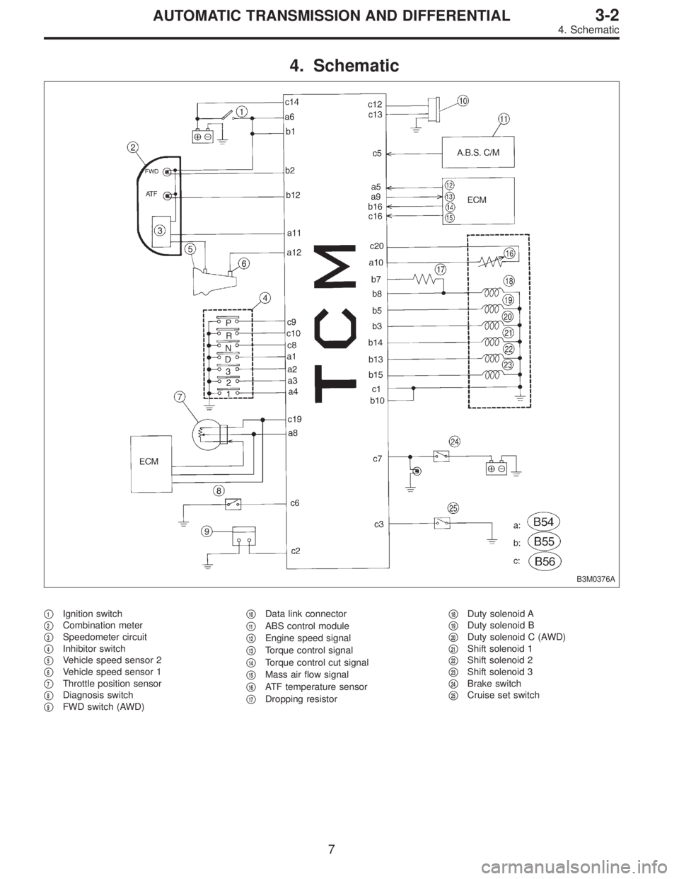
4. Schematic
B3M0376A
�1Ignition switch
�
2Combination meter
�
3Speedometer circuit
�
4Inhibitor switch
�
5Vehicle speed sensor 2
�
6Vehicle speed sensor 1
�
7Throttle position sensor
�
8Diagnosis switch
�
9FWD switch (AWD)�
10Data link connector
�
11ABS control module
�
12Engine speed signal
�
13Torque control signal
�
14Torque control cut signal
�
15Mass air flow signal
�
16ATF temperature sensor
�
17Dropping resistor�
18Duty solenoid A
�
19Duty solenoid B
�
20Duty solenoid C (AWD)
�
21Shift solenoid 1
�
22Shift solenoid 2
�
23Shift solenoid 3
�
24Brake switch
�
25Cruise set switch
7
3-2AUTOMATIC TRANSMISSION AND DIFFERENTIAL
4. Schematic
Page 1563 of 2248

I/O Signal
OBD0093A
Check with ignition switch ON.
ContentConnector
No.Terminal
No.Measuring conditions Voltage (V)
Back-up power supply B56 14 Ignition switch OFF")
5. Transmission Control Module (TCM)
I/O Signal
OBD0093A
Check with ignition switch ON.
ContentConnector
No.Terminal
No.Measuring conditions Voltage (V)
Back-up power supply B56 14 Ignition switch OFF 10—16
Ignition power supplyB54 6
Ignition switch ON (with engine OFF) 10—16
B55 1
Inhibitor switch“P”range switch B56 9Select lever in“P”range Less than 1
Select lever in any other than“P”
range (except“N”range)More than 8
“N”range switch B56 8Select lever in“N”range Less than 1
Select lever in any other than“N”
range (except“P”range)More than 8
“R”range switch B56 10Select lever in“R”range Less than 1
Select lever in any other than“R”
rangeMore than 6
“D”range switch B54 1Select lever in“D”range Less than 1
Select lever in any other than“D”
rangeMore than 6
“3”range switch B54 2Select lever in“3”range Less than 1
Select lever in any other than“3”
rangeMore than 6
“2”range switch B54 3Select lever in“2”range Less than 1
Select lever in any other than“2”
rangeMore than 6
“1”range switch B54 4Select lever in“1”range Less than 1
Select lever in any other than“1”
rangeMore than 6
Diagnosis switch B56 6Diagnosis connector connected Less than 1
Diagnosis connector disconnected More than 6
Brake switch B56 7Brake pedal depressed. More than 10.5
Brake pedal released. Less than 1
ABS signal B56 5ABS switch ON Less than 1
ABS switch OFF More than 6.5
AT diagnostic signal B55 12Ignition switch ON (With engine OFF) Less than 1
Ignition switch ON (With engine ON) More than 10
8
3-2AUTOMATIC TRANSMISSION AND DIFFERENTIAL
5. Transmission Control Module (TCM) I/O Signal
Page 1564 of 2248
Resistance to
body
(ohms)
Throttle position
sensorB54 8Throttle fully closed. 0.5±0.2
—
Throttle fully open. 4.6±0.3
Throttle positio")
ContentConnector
No.Terminal
No.Measuring conditionsVoltage
(V)Resistance to
body
(ohms)
Throttle position
sensorB54 8Throttle fully closed. 0.5±0.2
—
Throttle fully open. 4.6±0.3
Throttle position
sensor power
supplyB56 19Ignition switch ON
(With engine OFF)5.05±0.25—
ATF temperature
sensorB54 10ATF temperature 20°C(68°F) 3.45±0.55 2.1—2.9 k
ATF temperature 80°C (176°F) 1.2±0.2 275—375
Vehicle speed
sensor 1B54 12Vehicle stopped. 0
450—720
Vehicle speed at least 20 km/h (12
MPH)More than 1 (AC range)
Vehicle speed
sensor 2B56 11When vehicle is slowly moved at
least 2 meters (7ft).Less than 1)More than 9—
Engine speed
signalB54 5Ignition switch ON (with engine
OFF).More than 10.5
—
Ignition switch ON (with engine ON). 8—11
Cruise set signal B56 3When cruise control is set (SET
lamp ON).Less than 1
—
When cruise control is not set (SET
lamp OFF).More than 6.5
Torque control
signalB55 16 Ignition switch ON 5±1—
Torque control cut
signalB56 16 Ignition switch ON 6—9—
Mass air flow
signalB54 9 Engine idling after warm-up 0.5—1.2—
Shift solenoid 1 B55 141st or 4th gear More than 9
20—32
2nd or 3rd gear Less than 1
Shift solenoid 2 B55 131st or 2nd gear More than 9
20—32
3rd or 4th gear Less than 1
Shift solenoid 3 B55 15Select lever in“N”range (with
throttle fully closed).Less than 1
20—32
Select lever in“D”range (with
throttle fully closed).More than 9
Duty solenoid A B55 8Throttle fully closed (with engine
OFF) after warm-up.1.5—4.0
2.0—4.5
Throttle fully open (with engine
OFF) after warm-up.Less than 1
Dropping resistor B55 7Throttle fully closed (with engine
OFF) after warm-up.More than 8.5
12—18
Throttle fully open (with engine
OFF) after warm-up.Less than 1
Duty solenoid B B55 5When lock up occurs. More than 8.5
9—17
When lock up is released. Less than 0.5
Duty solenoid C
(AWD model only)B55 3Fuse on FWD switch More than 8.5
9—17 Fuse removed from FWD switch
(with throttle fully open and with
select lever in 1st gear).Less than 0.5
Sensor ground
line 1B54 7—0 Less than 1
Sensor ground
line 2B56 20—0 Less than 1
System ground
lineB56 1—0 Less than 1
Power system
ground lineB55 10—0 Less than 1
FWD switch
(AWD model only)B56 2Fuse removed. 6—9.1
—
Fuse installed. Less than 1
9
3-2AUTOMATIC TRANSMISSION AND DIFFERENTIAL
5. Transmission Control Module (TCM) I/O Signal
 Connect connector to TCM and CCM.
2) Lift-up the vehicle or set the vehicle on free rollers.
CAUTION:
On AWD models, raise all wheels off ground.
3) Start the")