Page 1544 of 2248
OBD0538
BJ: DTC P1502
—RADIATOR FAN FUNCTION PROBLEM
(FAN
—F)—
DESCRIPTION:
Refer to“BI: DTC P1500—RADIATOR FAN RELAY 1
CIRCUIT MALFUNCTION—[T11BI0]”.
DTC DETECTING CONDITION:
�Two consecutive trips with fault
TROUBLE SYMPTOM:
�Occurrence of noise
�Overheating
338
2-7ON-BOARD DIAGNOSTICS II SYSTEM
11. Diagnostics Chart with Trouble Code
Page 1547 of 2248
OBD0501
BK: DTC P1700
—THROTTLE POSITION SENSOR CIRCUIT
MALFUNCTION FOR AUTOMATIC
TRANSMISSION (ATTH)—
DESCRIPTION:
�The throttle position sensor provides electrical signals
corresponding to the throttle opening. The throttle opening
and accelerator depression speed are detected by this
throttle position sensor output.
�Detects throttle opening and determines shift point, line
pressure and lockup vehicle speed according to engine
load.
SOR CIRCUIT MALFUNCTION—[T11G0]”.>
DTC DETECTING CONDITION:
�Two consecutive trips with fault
TROUBLE SYMPTOM:
�Shift point too high or too low; engine brake not effected
in“3”range; excessive shift shock; excessive tight corner
“braking”
341
2-7ON-BOARD DIAGNOSTICS II SYSTEM
11. Diagnostics Chart with Trouble Code
Page 1549 of 2248
OBD0511
BL: DTC P1701
—CRUISE CONTROL SET SIGNAL CIRCUIT
MALFUNCTION FOR AUTOMATIC
TRANSMISSION (CRS)—
DESCRIPTION:
Detects operation of cruise control, and expands“4th”
operating range.
DTC DETECTING CONDITION:
�Two consecutive trips with fault
1.Check harness connector between TCM and
CCM.
2.Check input signal for TCM.
CAUTION:
After repair or replacement of faulty parts, conduct
CLEAR MEMORY and INSPECTION MODES.
[T3D0] and [T3E0].>
�
343
2-7ON-BOARD DIAGNOSTICS II SYSTEM
11. Diagnostics Chart with Trouble Code
Page 1552 of 2248
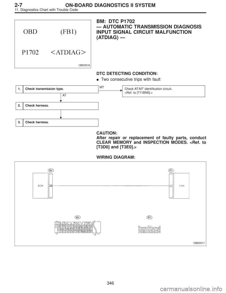
OBD0516
BM: DTC P1702
—AUTOMATIC TRANSMISSION DIAGNOSIS
INPUT SIGNAL CIRCUIT MALFUNCTION
(ATDIAG)—
DTC DETECTING CONDITION:
�Two consecutive trips with fault
1.Check transmission type.
AT
�MT
Check AT/MT identification circuit.
2.Check harness.
3.Check harness.
CAUTION:
After repair or replacement of faulty parts, conduct
CLEAR MEMORY and INSPECTION MODES.
[T3D0] and [T3E0].>
WIRING DIAGRAM:
OBD0517
�
�
346
2-7ON-BOARD DIAGNOSTICS II SYSTEM
11. Diagnostics Chart with Trouble Code
Page 1681 of 2248
![SUBARU LEGACY 1995 Service Repair Manual BRAKES
[ABS/TCS]
4-4b
Page
T DIAGNOSTICS
................................................................................2
1. Supplemental Restraint System “Airbag” ...............................](/manual-img/17/57432/w960_57432-1680.png "SUBARU LEGACY 1995 Service Repair Manual BRAKES
[ABS/TCS]
4-4b
Page
T DIAGNOSTICS
................................................................................2
1. Supplemental Restraint System “Airbag” ...............................")
BRAKES
[ABS/TCS]
4-4b
Page
T DIAGNOSTICS
................................................................................2
1. Supplemental Restraint System “Airbag” ................................................2
2. Pre-inspection ..........................................................................................2
3. Electrical Components Location ..............................................................4
4. Schematic ................................................................................................6
5. Control Module I/O Signal .......................................................................7
6. Diagnostics Chart for On-board Diagnosis System...............................13
7. Diagnostics Chart for Warning Light Circuit Failure ..............................18
8. Diagnostics Chart with Trouble Code ....................................................35
9. Select Monitor Function Mode ...............................................................88
10. Diagnostics Chart with Select Monitor...................................................96
11. General Diagnostics Table ...................................................................130
12. Phenomena Peculiar to the System ....................................................131
Page 1726 of 2248
5. CHECK SOURCES OF SIGNAL NOISE.
1) Check that the mobile phone, personal radio and other
wireless apparatus are correctly installed.
2) Check that the antenna and other possible noise
sources are distant enough from the sensor harness.
3) Check that the sealed wires of the front harness sensor
(in the engine room) are securely grounded.
4) Check that between ABS/TCS control module and the
rear sensor harness has the correct twist pitch.
Twist pitch:
25 mm (0.98 in) or less
6. CHECK HYDRAULIC UNIT OPERATIONS.
1) Operate the ABS sequence control and check that the
brake fluid pressure at the malfunctioning brake line
increases and decreases properly.
45
4-4bBRAKES
8. Diagnostics Chart with Trouble Code
Page 1775 of 2248
CodeDisplay screen
(FB0)Diagnostic items (select monitor FB1) Display screen (FB1)Ref. to
4-4b
Normal 11 NO TROUBLE Normal NO TROUBLE [T10C")
B: LIST OF TROUBLE CODE
Diagnostic items
(select monitor FB0)CodeDisplay screen
(FB0)Diagnostic items (select monitor FB1) Display screen (FB1)Ref. to
4-4b
Normal 11 NO TROUBLE Normal NO TROUBLE [T10C0]
Detection of FR sensor
hardware21 FR.SS HARDOpen circuit of FR sensor FR.SS OPEN [T10D1]
Short circuit of FR sensor FR.SS SHORT [T10D2]
Detection of FR sensor
software22 FR.SS SOFTFR sensor, variations in wheel speed FR.SS W.SPEED [T10E1]
FR sensor, reduced pressure mode FR.SS OR MV [T10E2]
FR sensor, wheel speed higher than prescribed FR.SS OVER [T10E3]
Detection of FL sensor
hardware23 FL.SS HARDOpen circuit of FL sensor FL.SS OPEN [T10F1]
Short circuit of FL sensor FL.SS SHORT [T10F2]
Detection of FL sensor
software24 FL.SS SOFTFL sensor, variations in wheel speed FL.SS W.SPEED [T10G1]
FL sensor, reduced pressure mode FL.SS OR MV [T10G2]
FL sensor, wheel speed higher than prescribed FL.SS OVER [T10G3]
Detection of RR sensor
hardware25 RR.SS HARDOpen circuit of RR sensor RR.SS OPEN [T10H1]
Short circuit of RR sensor RR.SS SHORT [T10H2]
Detection of RR sensor
software26 RR.SS SOFTRR sensor, variations in wheel speed RR.SS W.SPEED [T10I1]
RR sensor, reduced pressure mode RR.SS OR MV [T10I2]
RR sensor, wheel speed higher than prescribed RR.SS OVER [T10I3]
Detection of RL sensor
hardware27 RL.SS HARDOpen circuit of RL sensor RL.SS OPEN [T10J1]
Short circuit of RL sensor RL.SS SHORT [T10J2]
Detection of RL sensor
software28 RL.SS SOFTRL sensor, variations in wheel speed RL.SS W.SPEED [T10K1]
RL sensor, reduced pressure mode RL.SS OR MV [T10K2]
RL sensor, wheel speed higher than prescribed RL.SS OVER [T10K3]
Abnormal FR.IN valve 31 FR.IN VALVE Abnormal FR.IN valve FR.IN VALVE [T10L0]
Abnormal FR.OUT
valve32 FR.OUT VALVE Abnormal FR.OUT valve FR.OUT VALVE [T10M0]
Abnormal FL.IN valve 33 FL.IN VALVE Abnormal FL.IN valve FL.IN VALVE [T10N0]
Abnormal FL.OUT
valve34 FL.OUT VALVE Abnormal FL.OUT valve FL.OUT VALVE [T10O0]
Abnormal RR.IN valve 35 RR.IN VALVE Abnormal RR.IN valve RR.IN VALVE [T10P0]
Abnormal RR.OUT
valve36 RR.OUT VALVE Abnormal RR.OUT valve RR.OUT VALVE [T10Q0]
Abnormal RL.IN valve 37 RL.IN VALVE Abnormal RL.IN valve RL.IN VALVE [T10R0]
Abnormal RL.OUT
valve38 RL.OUT VALVE Abnormal RL.OUT valve RL.OUT VALVE [T10S0]
Abnormal ECM 41 ECU Abnormal ECM ECU [T10T0]
Abnormal line voltage 42 HIGH VOLTAGE Abnormal line voltage HIGH VOLTAGE [T10U0]
Abnormal EGI commu-
nication line43 EGI LINE Abnormal EGI communication line EGI LINE [T10V0]
Abnormal valve relay 51 V.RELAYValve relay ON failure V.RELAY ON [T10W1]
Valve relay OFF failure V.RELAY OFF [T10W2]
Abnormal motor sys-
tem52 MOTORMotor relay ON failure MOTOR ON [T10X1]
Motor relay OFF failure MOTOR OFF [T10X2]
94
4-4bBRAKES
10. Diagnostic Chart with Select Monitor
Page 1792 of 2248

B4M0518
S: TROUBLE CODE 38
RL.OUT VALVE
—Faulty rear left outlet solenoid valve—
DIAGNOSIS:
�Faulty harness/connector
�Faulty solenoid valve in hydraulic unit
�Faulty ABS/TCS control module
TROUBLE SYMPTOM:
�ABS and TCS do not operate.
�ABS sequence control does not operate.
�TCS sequence control does not operate.
�Air bleeding mode does not operate.
NOTE:
The procedures used are the same as those for FR.OUT
VA LV E .
B4M0519
T: TROUBLE CODE 41
ECU
—Faulty ABS/TCS control module—
DIAGNOSIS:
�Faulty ABS/TCS control module
�Faulty harness/connector
TROUBLE SYMPTOM:
�ABS does not operate.
�TCS does not operate.
1. Check ground circuit of ABS/TCS control
module.
OK
�Not OK
Repair harness/connector.
2. Check harness connectors between power
supply generator, battery and ABS/TCS con-
trol module.
OK
�Not OK
Repair harness/connector.
3. Check sources of signal noise.
OK
�Not OK
Repair noise sources.
Replace ABS/TCS control module.
�
�
�
111
4-4bBRAKES
10. Diagnostic Chart with Select Monitor
—
DESCRIPTION:
Detects operation of cruise control, and expands“4th”
operating range.
DTC D")
 Check that the mobile phone, personal radio and other
wireless apparatus are correctly installed.
2) Check that the antenna and other possible noise
sources are di")