Page 1416 of 2248
OBD0277
U: DTC P0301
—CYLINDER 1 MISFIRE DETECTED (MIS
—1)
—
OBD0278
V: DTC P0302
—CYLINDER 2 MISFIRE DETECTED (MIS
—2)
—
OBD0279
W: DTC P0303
—CYLINDER 3 MISFIRE DETECTED (MIS
—3)
—
OBD0280
X: DTC P0304
—CYLINDER 4 MISFIRE DETECTED (MIS
—4)
—
DTC DETECTING CONDITION:
�Two consecutive trips with fault
�Immediately at fault recognition (A misfire which could
damage catalyst occurs.)
TROUBLE SYMPTOM:
�Engine stalls.
�Erroneous idling
�Rough driving
210
2-7ON-BOARD DIAGNOSTICS II SYSTEM
11. Diagnostics Chart with Trouble Code
Page 1425 of 2248
OBD0716A
1
CHECK HARNESS.
1) Turn ignition switch to OFF.
2) Disconnect connector from ECM.
3) Measure resistance between ECM harness connector
and body.
: Connector & terminal
(B84) No. 30—Body/700 kΩ, or more
: Go to step 2.
: Go to next.
OBD0716A
: Connector & terminal
(B84) No. 30—Body/400 kΩ, or less
: Go to step 3.
: Go to step 4.
B2M0244A
2
CHECK KNOCK SENSOR.
1) Disconnect connector from knock sensor.
2) Measure voltage between knock sensor connector and
body.
: Connector & terminal
(E14) No. 1—Body/700 kΩ, or more
: Check and repair the following items.
�Open circuit of the harness between knock sen-
sor connector and ECM connector
�Poor contact of the knock sensor connector
�Poor contact of coupling connector (B21)
: Go to next.
: Check for secure tightening of the knock
sensor installation bolts.
: Tighten knock sensor installation bolts securely.
: Replace knock sensor.
219
2-7ON-BOARD DIAGNOSTICS II SYSTEM
11. Diagnostics Chart with Trouble Code
Page 1430 of 2248
2
CHECK CRANKSHAFT POSITION SENSOR.
: Check for secure tightening of the installa-
tion bolts of the crankshaft position sensor.
: Tighten securely.
: Go to the next step.
G2M0639
1) Remove crankshaft position sensor.
2) Measure resistance between connector terminals of
crankshaft position sensor.
: Terminals
No. 1—No. 2/1—4kΩ
: Repair poor contact in crankshaft position sensor
connector.
: Replace crankshaft position sensor.
224
2-7ON-BOARD DIAGNOSTICS II SYSTEM
11. Diagnostics Chart with Trouble Code
Page 1434 of 2248
2
CHECK CAMSHAFT POSITION SENSOR.
: Check for secure tightening of the installa-
tion bolts of the camshaft position sensor.
: Tighten securely.
: Go to the next step.
G2M0639
1) Remove camshaft position sensor.
2) Measure resistance between connector terminals of
camshaft position sensor.
: Terminals
No. 1—No. 2/1—4kΩ
: Repair poor contact in camshaft position sensor
connector.
: Replace camshaft position sensor.
228
2-7ON-BOARD DIAGNOSTICS II SYSTEM
11. Diagnostics Chart with Trouble Code
Page 1436 of 2248
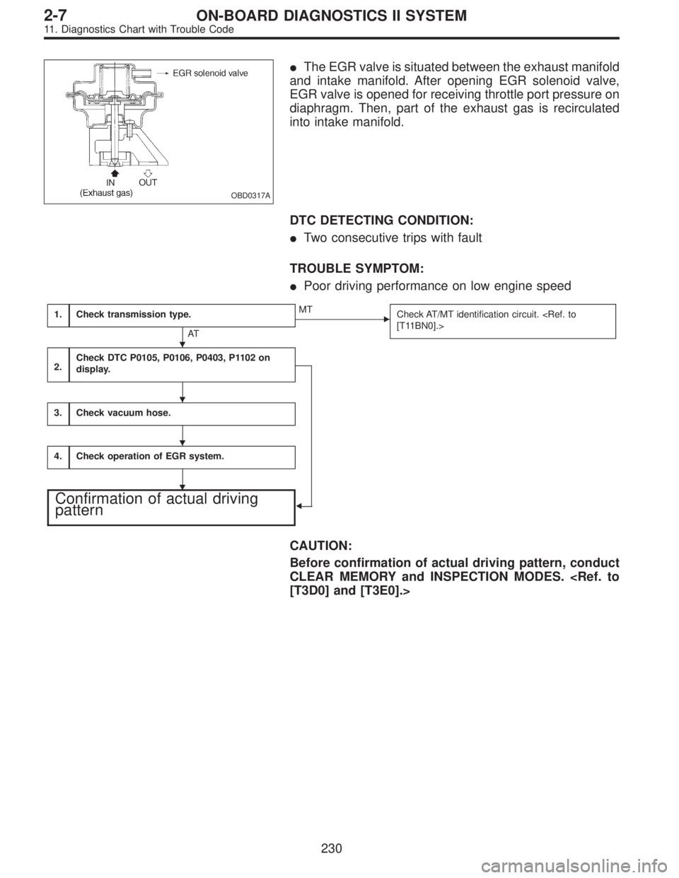
OBD0317A
�The EGR valve is situated between the exhaust manifold
and intake manifold. After opening EGR solenoid valve,
EGR valve is opened for receiving throttle port pressure on
diaphragm. Then, part of the exhaust gas is recirculated
into intake manifold.
DTC DETECTING CONDITION:
�Two consecutive trips with fault
TROUBLE SYMPTOM:
�Poor driving performance on low engine speed
1.Check transmission type.
AT
�MT
Check AT/MT identification circuit.
[T11BN0].>
2.Check DTC P0105, P0106, P0403, P1102 on
display.
�
3.Check vacuum hose.
4.Check operation of EGR system.
Confirmation of actual driving
pattern
CAUTION:
Before confirmation of actual driving pattern, conduct
CLEAR MEMORY and INSPECTION MODES.
[T3D0] and [T3E0].>
�
�
�
�
230
2-7ON-BOARD DIAGNOSTICS II SYSTEM
11. Diagnostics Chart with Trouble Code
Page 1441 of 2248
OBD0323
AC: DTC P0403
—EXHAUST GAS RECIRCULATION CIRCUIT
MALFUNCTION (EGRSOL)—
OBD0324A
DESCRIPTION:
The EGR solenoid valve is situated between the BPT and
EGR valve. EGR solenoid valve is opened by a signal
emitted from the ECM. Therefore, throttle port pressure is
transmitted to diaphragm of EGR valve.
DTC DETECTING CONDITION:
�Two consecutive trips with fault
TROUBLE SYMPTOM:
�Poor driving performance on low engine speed
1.Check transmission type.
AT
�MT
Check AT/MT identification circuit.
2.Check output signal from ECM.
�
3.Check harness.
4.Check harness.
5.Check EGR solenoid valve.
6.Check power supply to EGR solenoid valve.
CAUTION:
After repair or replacement of faulty parts, conduct
CLEAR MEMORY and INSPECTION MODES.
[T3D0] and [T3E0].>
�
�
�
�
235
2-7ON-BOARD DIAGNOSTICS II SYSTEM
11. Diagnostics Chart with Trouble Code
Page 1451 of 2248
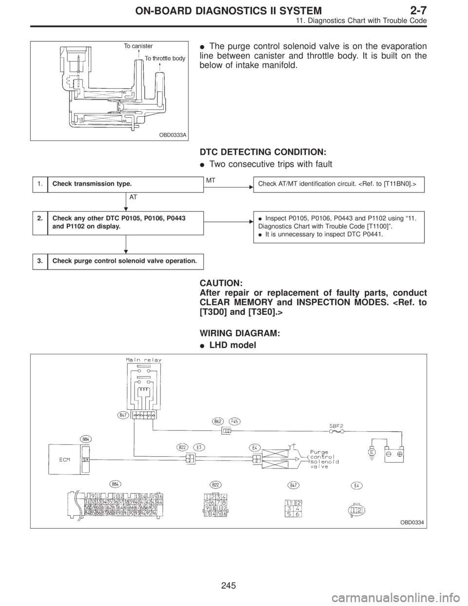
OBD0333A
�The purge control solenoid valve is on the evaporation
line between canister and throttle body. It is built on the
below of intake manifold.
DTC DETECTING CONDITION:
�Two consecutive trips with fault
1.Check transmission type.
AT
�MT
Check AT/MT identification circuit.
2.Check any other DTC P0105, P0106, P0443
and P1102 on display.��Inspect P0105, P0106, P0443 and P1102 using“11 .
Diagnostics Chart with Trouble Code [T1100]”.
�It is unnecessary to inspect DTC P0441.
3.Check purge control solenoid valve operation.
CAUTION:
After repair or replacement of faulty parts, conduct
CLEAR MEMORY and INSPECTION MODES.
[T3D0] and [T3E0].>
WIRING DIAGRAM:
�LHD model
OBD0334
�
�
245
2-7ON-BOARD DIAGNOSTICS II SYSTEM
11. Diagnostics Chart with Trouble Code
Page 1454 of 2248
OBD0335
AF: DTC P0443
—EVAPORATIVE EMISSION CONTROL
SYSTEM PURGE CONTROL VALVE CIRCUIT
MALFUNCTION (CPC)—
DESCRIPTION:
Refer to“AE: DTC P0441—EVAPORATIVE EMISSION
CONTROL SYSTEM INCORRECT PURGE FLOW—
[T11AE0]”.
DTC DETECTING CONDITION:
�Two consecutive trips with fault
TROUBLE SYMPTOM:
�Erroneous idling
1.Check output signal from ECM.
�
2.Check harness.
3.Check harness.
4.Check purge control solenoid valve.
5.Check power supply to purge control solenoid
valve.
CAUTION:
After repair or replacement of faulty parts, conduct
CLEAR MEMORY and INSPECTION MODES.
[T3D0] and [T3E0].>
�
�
�
248
2-7ON-BOARD DIAGNOSTICS II SYSTEM
11. Diagnostics Chart with Trouble Code

—
OBD0278
V: DTC P0302
—CYLINDER 2 MISFIRE DETECTED (MIS
—2)
—
OBD0279
W: DTC P0303
—CYLINDER 3 MISFIRE DETECTED (MIS
—3)
—")
 Turn ignition switch to OFF.
2) Disconnect connector from ECM.
3) Measure resistance between ECM harness connector
and body.
: Connector & terminal
(B84) No. 30—Body/700")
 Remove crankshaft")
 Remove camshaft posit")
—
OBD0324A
DESCRIPTION:
The EGR solenoid valve is situated between the BPT and
EGR valve. EGR solenoid valve is opened")
—
DESCRIPTION:
Refer to“AE: DTC P0441—EVAPORATIVE EMISSION
CONTROL SYSTEM INCORRECT PURG")