Page 1468 of 2248
OBD0370
AI: DTC P0506
—IDLE CONTROL SYSTEM RPM LOWER
THAN EXPECTED (ISC
—L)—
DESCRIPTION:
Refer to“AH: DTC P0505—IDLE CONTROL SYSTEM
MALFUNCTION—[T11AH0]”.
DTC DETECTING CONDITION:
�Two consecutive trips with fault
TROUBLE SYMPTOM:
�Engine is difficult to start.
�Engine does not start.
�Erroneous idling
�Engine stalls.
1.Check DTC P0505 on display.
No
�Ye s
�Inspect DTC P0505 using“11. Diagnostics Chart
with Trouble Code [T1100]”.
�In this case, it is unnecessary to inspect DTC
P0506.
2.Check air intake system.
CAUTION:
After repair or replacement of faulty parts, conduct
CLEAR MEMORY and INSPECTION MODES.
[T3D0] and [T3E0].>
�
262
2-7ON-BOARD DIAGNOSTICS II SYSTEM
11. Diagnostics Chart with Trouble Code
Page 1470 of 2248
OBD0371
AJ: DTC P0507
—IDLE CONTROL SYSTEM RPM HIGHER
THAN EXPECTED (ISC
—H)—
DESCRIPTION:
Refer to“AH: DTC P0505—IDLE CONTROL SYSTEM
MALFUNCTION—[T11AH0]”.
DTC DETECTING CONDITION:
�Two consecutive trips with fault
TROUBLE SYMPTOM:
�Engine keeps running at higher revolution than specified
idling revolution.
1.Check DTC P0505 on display.
No
�Ye s
�Inspect DTC P0505 using“11. Diagnostics Chart
with Trouble Code [T1100]”.
�In this case, it is unnecessary to inspect DTC
P0507.
2.Check air intake system.
CAUTION:
After repair or replacement of faulty parts, conduct
CLEAR MEMORY and INSPECTION MODES.
[T3D0] and [T3E0].>
�
264
2-7ON-BOARD DIAGNOSTICS II SYSTEM
11. Diagnostics Chart with Trouble Code
Page 1472 of 2248
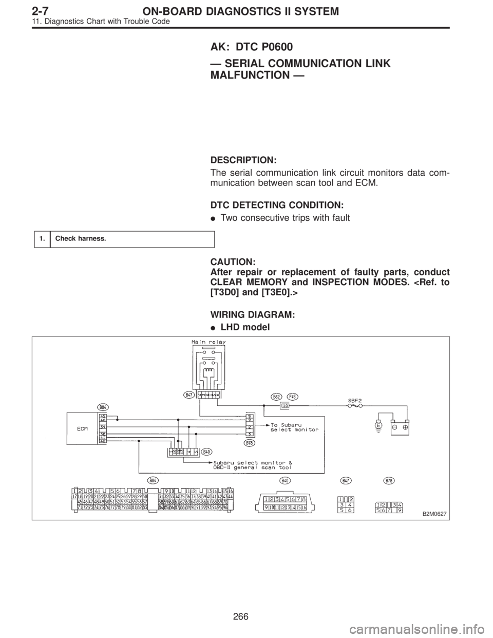
AK: DTC P0600
—SERIAL COMMUNICATION LINK
MALFUNCTION—
DESCRIPTION:
The serial communication link circuit monitors data com-
munication between scan tool and ECM.
DTC DETECTING CONDITION:
�Two consecutive trips with fault
1.Check harness.
CAUTION:
After repair or replacement of faulty parts, conduct
CLEAR MEMORY and INSPECTION MODES.
[T3D0] and [T3E0].>
WIRING DIAGRAM:
�LHD model
B2M0627
266
2-7ON-BOARD DIAGNOSTICS II SYSTEM
11. Diagnostics Chart with Trouble Code
Page 1474 of 2248
OBD0723A
4) Measure resistance between ECM harness connector
and body.
: Connector & terminal
(B84) No. 41—Body / 10Ω, or less
: Repair short circuit of harness between ECM con-
nector and data link connector.
: Repair poor contact in ECM connector and data
link connector.
OBD0376
AL: DTC P0601
—INTERNAL CONTROL MODULE MEMORY
CHECK SUM ERROR (RAM)—
DESCRIPTION:
The RAM monitors the ECM microcomputer operation.
DTC DETECTING CONDITION:
�Two consecutive trips with fault
TROUBLE SYMPTOM:
�Engine does not start.
�Engine stalls.
1.Check DTC P0601 on display.
Ye s
Replace ECM.
CAUTION:
After repair or replacement of faulty parts, conduct
CLEAR MEMORY and INSPECTION MODES.
[T3D0] and [T3E0].>
�
268
2-7ON-BOARD DIAGNOSTICS II SYSTEM
11. Diagnostics Chart with Trouble Code
Page 1477 of 2248
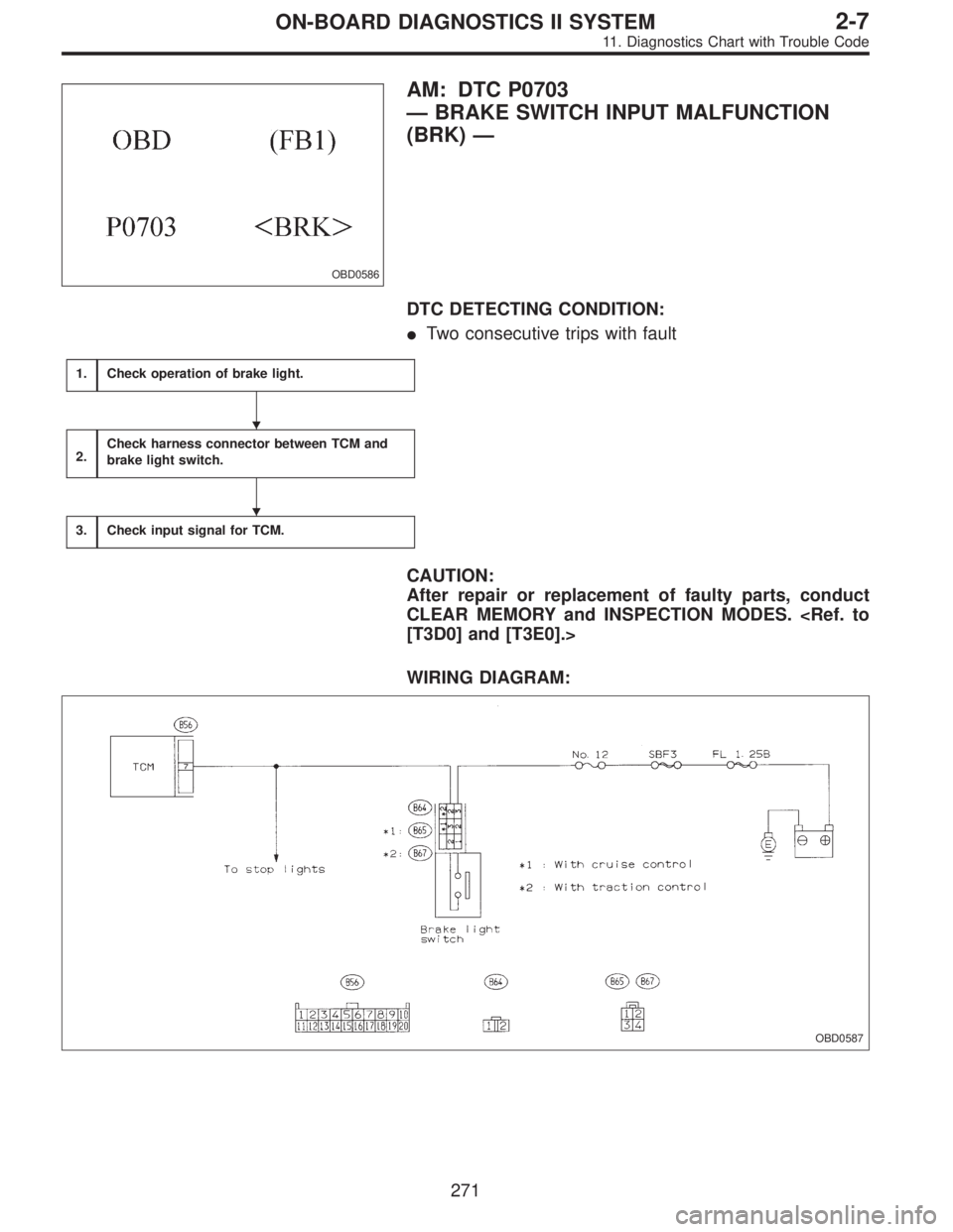
OBD0586
AM: DTC P0703
—BRAKE SWITCH INPUT MALFUNCTION
(BRK)—
DTC DETECTING CONDITION:
�Two consecutive trips with fault
1.Check operation of brake light.
2.Check harness connector between TCM and
brake light switch.
3.Check input signal for TCM.
CAUTION:
After repair or replacement of faulty parts, conduct
CLEAR MEMORY and INSPECTION MODES.
[T3D0] and [T3E0].>
WIRING DIAGRAM:
OBD0587
�
�
271
2-7ON-BOARD DIAGNOSTICS II SYSTEM
11. Diagnostics Chart with Trouble Code
Page 1480 of 2248
—
OBD0592A
DESCRIPTION:
�The inhibitor switch assures safety when starting the
engine. This switch is mounted on the right")
OBD0591
AN: DTC P0705
—TRANSMISSION RANGE SENSOR CIRCUIT
MALFUNCTION (RNG)—
OBD0592A
DESCRIPTION:
�The inhibitor switch assures safety when starting the
engine. This switch is mounted on the right side of the
transmission case, and is operated by the range selector
lever.
�When the selector lever is set to“P”or“N”, the electri-
cal circuit is connected in the inhibitor switch and the starter
circuit is energized for cracking the engine.
�When the selector lever is set to“R”,“D”,“3”,“2”,or“1”
range, the electrical circuit is disconnected in the inhibitor
switch. Hence engine cranking is disabled. In the“R”
range, the back-up light circuit is completed in the switch,
and the back-up lights come on.
DTC DETECTING CONDITION:
�Two consecutive trips with fault
TROUBLE SYMPTOM:
�Starter does not rotate when selector lever is in“P”or
“N”range.
�Starter rotates when selector lever is in“R”,“D”,“3”,“2”
or“1”range.
�Engine brake is not effected when selector lever is in“3”
range.
�Shift characteristics are erroneous.
274
2-7ON-BOARD DIAGNOSTICS II SYSTEM
11. Diagnostics Chart with Trouble Code
Page 1485 of 2248
OBD0380
AO: DTC P0710
—TRANSMISSION FLUID TEMPERATURE
SENSOR CIRCUIT MALFUNCTION (ATF)—
H2M1145
DESCRIPTION:
This sensor is mounted to the control valve in the transmis-
sion. It detects temperature change as an analog electrical
signal. The output characteristics of the sensor are shown
in the illustration.
DTC DETECTING CONDITION:
�Two consecutive trips with fault
TROUBLE SYMPTOM:
�No shift up to 4th speed (after engine warm-up)
�No lock-up occurs. (after engine warm-up)
�Excessive shift shock
279
2-7ON-BOARD DIAGNOSTICS II SYSTEM
11. Diagnostics Chart with Trouble Code
Page 1487 of 2248
![SUBARU LEGACY 1995 Service Repair Manual OBD0392
AP: DTC P0720
—OUTPUT SPEED SENSOR (VEHICLE
SPEED SENSOR 1) CIRCUIT MALFUNCTION
(ATVSP)—
OBD0393A
DESCRIPTION:
[FWD model]
�The vehicle speed sensor 1 is mounted to the transmis-
sion case](/manual-img/17/57432/w960_57432-1486.png "SUBARU LEGACY 1995 Service Repair Manual OBD0392
AP: DTC P0720
—OUTPUT SPEED SENSOR (VEHICLE
SPEED SENSOR 1) CIRCUIT MALFUNCTION
(ATVSP)—
OBD0393A
DESCRIPTION:
[FWD model]
�The vehicle speed sensor 1 is mounted to the transmis-
sion case")
OBD0392
AP: DTC P0720
—OUTPUT SPEED SENSOR (VEHICLE
SPEED SENSOR 1) CIRCUIT MALFUNCTION
(ATVSP)—
OBD0393A
DESCRIPTION:
[FWD model]
�The vehicle speed sensor 1 is mounted to the transmis-
sion case (at the rear side of the case). The sensor outputs
a pulse signal which is transmission to the TCM where it is
converted to vehicle speed.
�Vehicle speed sensor 1 on FWD model detects front-
wheel speed.
OBD0394A
[AWD]
�The vehicle speed sensor 1 (output shaft rotation sen-
sor) is mounted to the extension case (from the outside of
the case). The sensor outputs a pulse signal which is trans-
mitted to the TCM where it is converted to vehicle speed.
�The transfer clutch drum is connected directly to the rear
wheel driving propeller shaft. Vehicle speed sensor 1 on
the AWD model defects rear-wheel speed.
DTC DETECTING CONDITION:
�Two consecutive trips with fault
TROUBLE SYMPTOM:
�No shift or excessive tight corner“braking”
281
2-7ON-BOARD DIAGNOSTICS II SYSTEM
11. Diagnostics Chart with Trouble Code
 Measure resistance between ECM harness connector
and body.
: Connector & terminal
(B84) No. 41—Body / 10Ω, or less
: Repair short circuit of harness between ECM con-
nector and data li")
—
H2M1145
DESCRIPTION:
This sensor is mounted to the control valve in the transmis-
sion. It detects temperatu")