Page 860 of 2248
B4M0063
6. Mode Door Motor
A: REMOVAL
1) Remove instrument panel.
2) Remove mode door motor.
B4M0064A
B: INSPECTION
1) When approx. 12 V is applied to the mode door motor
terminals, mode door motor operates as follows:
LHD model
Terminal No.
Mode door motor
21
Polarity of power supply
terminalsMode door motor
operationDirection of linkage
rotation
+ VENT,DEF Clockwise
+ DEF,VENT Counterclockwise
RHD model
Terminal No.
Mode door motor
76
Polarity of power supply
terminalsMode door motor
operationDirection of linkage
rotation
+ VENT,DEF Clockwise
+ DEF,VENT Counterclockwise
2) Check mode door motor position switch.
When the mode door motor is moved to each mode posi-
tion by using the mode selector switch, check if continuity
exists between each terminal as follows:
LHD model
Mode selector switch
positionsTerminal No.
VENT 8 or 7
9 (GND) BI-LEV 6 or 7
HEAT 5or6
DEF/HEAT 4 or 5
DEF 3or4
18
4-6SERVICE PROCEDURE
6. Mode Door Motor
Page 1065 of 2248
G5M0308
6) Disconnect airbag connector and horn connector on
back of airbag module. Remove airbag module, and place
it with pad side facing upward.
G5M0332
7) Using steering puller, remove steering wheel.
CAUTION:
Do not allow connector to interfere when removing
steering wheel.
B5M0106
8) Remove steering column covers.
9) Removing two retaining screws, remove combination
switch.
B: ADJUSTMENT
1. CENTERING ROLL CONNECTOR
Before installing combination switch and steering gearbox,
make sure to center roll connector built into combination
switch.
1) Make sure that front wheels are positioned straight
ahead.
2) Install gearbox, steering shaft and combination switch
properly. Turn roll connector pinclockwiseuntil it stops.
B5M0107A
3) Then, back off roll connector pin approximately 2.65
turns until“CENTER”appears on indicator with“�”marks
aligned.
19
5-5SERVICE PROCEDURE
7. Combination Switch
Page 1067 of 2248
1. Engine Electrical
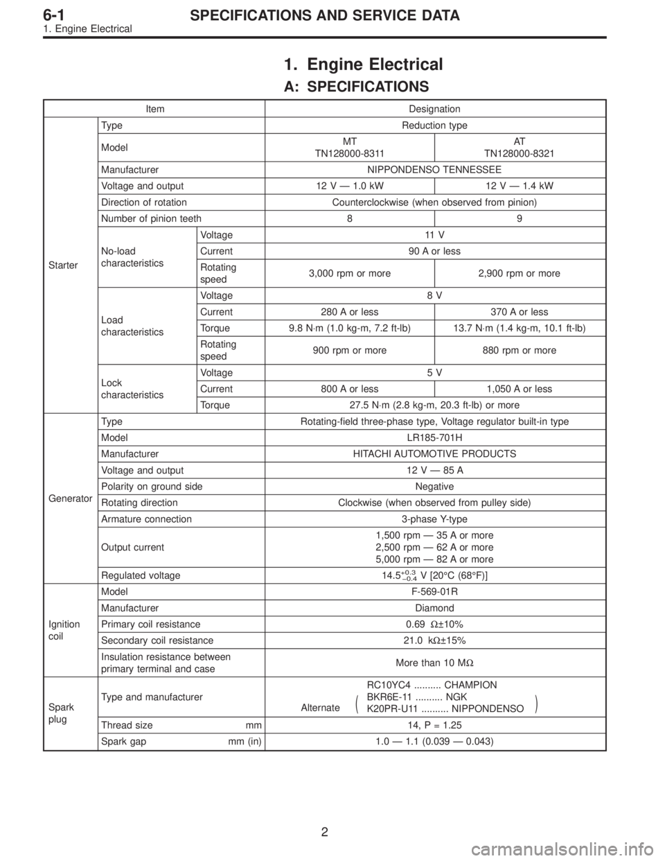
A: SPECIFICATIONS
Item Designation
StarterType Reduction type
ModelMT
TN128000-8311AT
TN128000-8321
Manufacturer NIPPONDENSO TENNESSEE
Voltage and output 12 V — 1.0 kW 12 V — 1.4 kW
Direction of rotation Counterclockwise (when observed from pinion)
Number of pinion teeth 8 9
No-load
characteristicsVoltage 11 V
Current 90 A or less
Rotating
speed3,000 rpm or more 2,900 rpm or more
Load
characteristicsVoltage 8 V
Current 280 A or less 370 A or less
Torque 9.8 N⋅m (1.0 kg-m, 7.2 ft-lb) 13.7 N⋅m (1.4 kg-m, 10.1 ft-lb)
Rotating
speed900 rpm or more 880 rpm or more
Lock
characteristicsVoltage 5 V
Current 800 A or less 1,050 A or less
Torque 27.5 N⋅m (2.8 kg-m, 20.3 ft-lb) or more
GeneratorType Rotating-field three-phase type, Voltage regulator built-in type
Model LR185-701H
Manufacturer HITACHI AUTOMOTIVE PRODUCTS
Voltage and output 12 V — 85 A
Polarity on ground side Negative
Rotating direction Clockwise (when observed from pulley side)
Armature connection 3-phase Y-type
Output current1,500 rpm — 35 A or more
2,500 rpm — 62 A or more
5,000 rpm — 82 A or more
Regulated voltage 14.5
+0.3
0.4V [20°C (68°F)]
Ignition
coilModel F-569-01R
Manufacturer Diamond
Primary coil resistance 0.69Ω±10%
Secondary coil resistance 21.0 kΩ±15%
Insulation resistance between
primary terminal and caseMore than 10 MΩ
Spark
plugType and manufacturerRC10YC4 .......... CHAMPION
Alternate
(BKR6E-11 .......... NGK
K20PR-U11 .......... NIPPONDENSO)
Thread size mm 14, P = 1.25
Spark gap mm (in) 1.0 — 1.1 (0.039 — 0.043)
2
6-1SPECIFICATIONS AND SERVICE DATA
1. Engine Electrical
Page 1078 of 2248
B6M0436
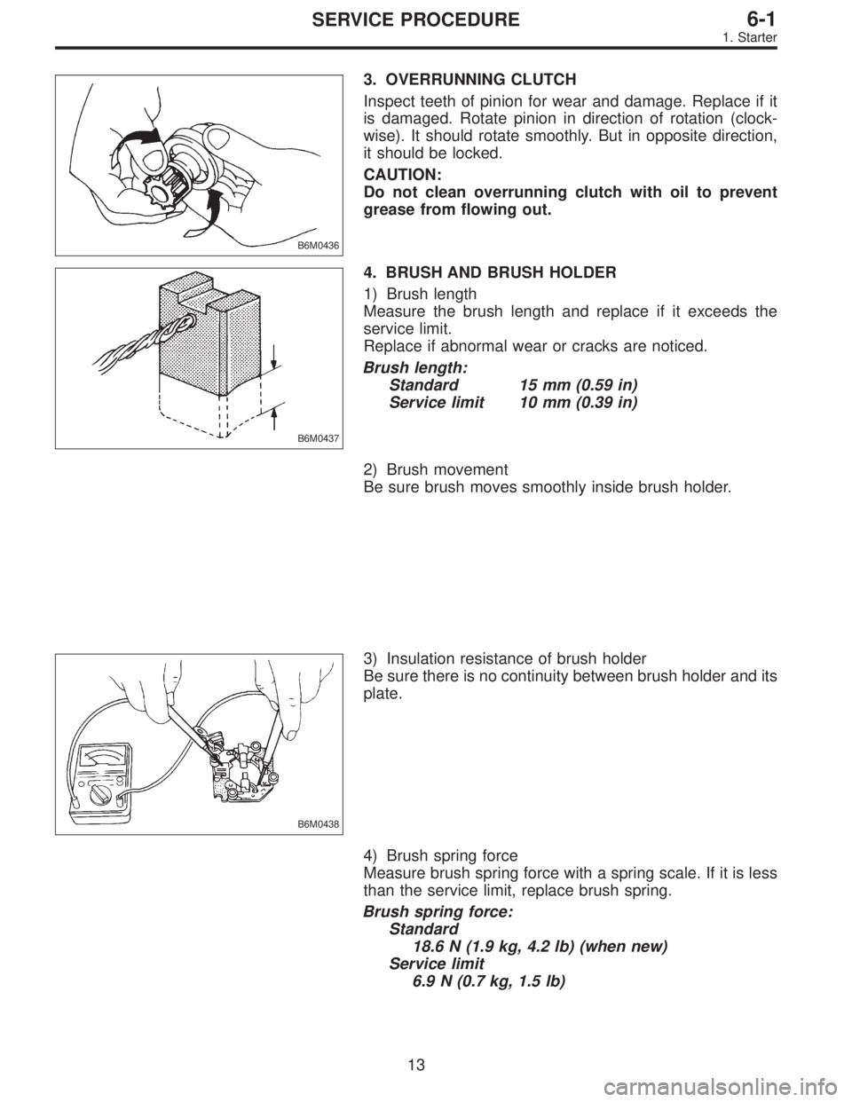
3. OVERRUNNING CLUTCH
Inspect teeth of pinion for wear and damage. Replace if it
is damaged. Rotate pinion in direction of rotation (clock-
wise). It should rotate smoothly. But in opposite direction,
it should be locked.
CAUTION:
Do not clean overrunning clutch with oil to prevent
grease from flowing out.
B6M0437
4. BRUSH AND BRUSH HOLDER
1) Brush length
Measure the brush length and replace if it exceeds the
service limit.
Replace if abnormal wear or cracks are noticed.
Brush length:
Standard 15 mm (0.59 in)
Service limit 10 mm (0.39 in)
2) Brush movement
Be sure brush moves smoothly inside brush holder.
B6M0438
3) Insulation resistance of brush holder
Be sure there is no continuity between brush holder and its
plate.
4) Brush spring force
Measure brush spring force with a spring scale. If it is less
than the service limit, replace brush spring.
Brush spring force:
Standard
18.6 N (1.9 kg, 4.2 lb) (when new)
Service limit
6.9 N (0.7 kg, 1.5 lb)
13
6-1SERVICE PROCEDURE
1. Starter
Page 1138 of 2248
B6M0349
15. Horn and Cigarette Lighter
A: REMOVAL AND INSTALLATION
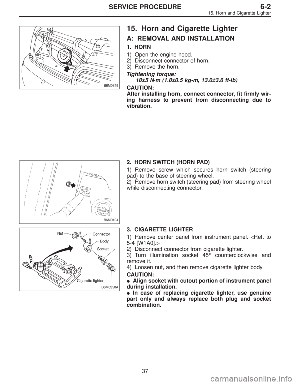
1. HORN
1) Open the engine hood.
2) Disconnect connector of horn.
3) Remove the horn.
Tightening torque:
18±5 N⋅m (1.8±0.5 kg-m, 13.0±3.6 ft-lb)
CAUTION:
After installing horn, connect connector, fit firmly wir-
ing harness to prevent from disconnecting due to
vibration.
B6M0124
2. HORN SWITCH (HORN PAD)
1) Remove screw which secures horn switch (steering
pad) to the base of steering wheel.
2) Remove horn switch (steering pad) from steering wheel
while disconnecting connector.
B6M0350A
3. CIGARETTE LIGHTER
1) Remove center panel from instrument panel.
5-4 [W1A0].>
2) Disconnect connector from cigarette lighter.
3) Turn illumination socket 45°counterclockwise and
remove it.
4) Loosen nut, and then remove cigarette lighter body.
CAUTION:
�Align socket with cutout portion of instrument panel
during installation.
�In case of replacing cigarette lighter, use genuine
part only and always replace both plug and socket
combination.
37
6-2SERVICE PROCEDURE
15. Horn and Cigarette Lighter
Page 1234 of 2248
OBD0006C
B: OBD-II GENERAL SCAN TOOL
1. HOW TO USE OBD-II GENERAL SCAN TOOL
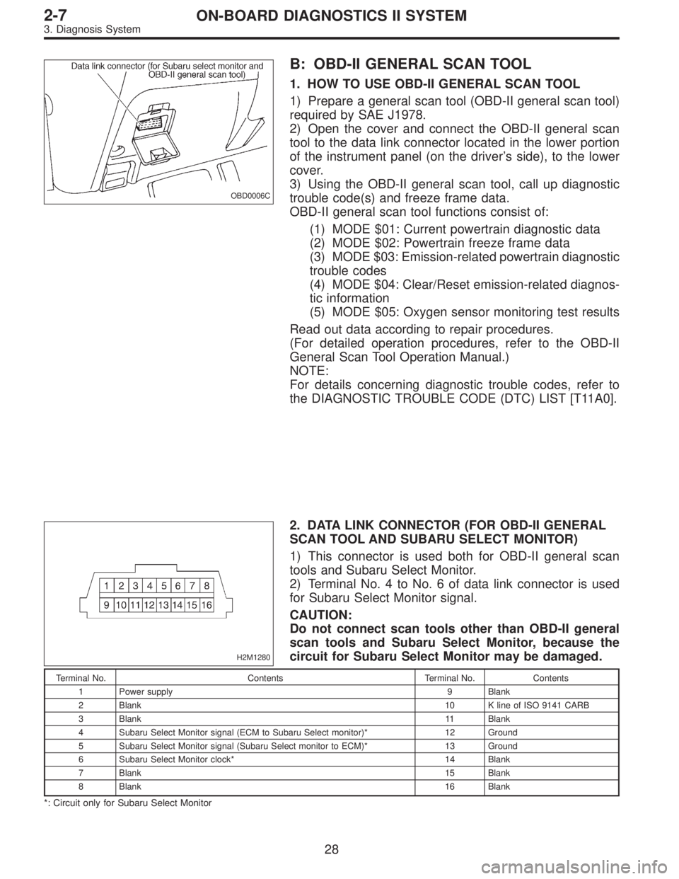
1) Prepare a general scan tool (OBD-II general scan tool)
required by SAE J1978.
2) Open the cover and connect the OBD-II general scan
tool to the data link connector located in the lower portion
of the instrument panel (on the driver’s side), to the lower
cover.
3) Using the OBD-II general scan tool, call up diagnostic
trouble code(s) and freeze frame data.
OBD-II general scan tool functions consist of:
(1) MODE $01: Current powertrain diagnostic data
(2) MODE $02: Powertrain freeze frame data
(3) MODE $03: Emission-related powertrain diagnostic
trouble codes
(4) MODE $04: Clear/Reset emission-related diagnos-
tic information
(5) MODE $05: Oxygen sensor monitoring test results
Read out data according to repair procedures.
(For detailed operation procedures, refer to the OBD-II
General Scan Tool Operation Manual.)
NOTE:
For details concerning diagnostic trouble codes, refer to
the DIAGNOSTIC TROUBLE CODE (DTC) LIST [T11A0].
H2M1280
2. DATA LINK CONNECTOR (FOR OBD-II GENERAL
SCAN TOOL AND SUBARU SELECT MONITOR)
1) This connector is used both for OBD-II general scan
tools and Subaru Select Monitor.
2) Terminal No. 4 to No. 6 of data link connector is used
for Subaru Select Monitor signal.
CAUTION:
Do not connect scan tools other than OBD-II general
scan tools and Subaru Select Monitor, because the
circuit for Subaru Select Monitor may be damaged.
Terminal No. Contents Terminal No. Contents
1 Power supply 9 Blank
2 Blank10 K line of ISO 9141 CARB
3 Blank11 Blank
4 Subaru Select Monitor signal (ECM to Subaru Select monitor)* 12 Ground
5 Subaru Select Monitor signal (Subaru Select monitor to ECM)* 13 Ground
6 Subaru Select Monitor clock* 14 Blank
7 Blank15 Blank
8 Blank16 Blank
*: Circuit only for Subaru Select Monitor
28
2-7ON-BOARD DIAGNOSTICS II SYSTEM
3. Diagnosis System
Page:
< prev 1-8 9-16 17-24
![SUBARU LEGACY 1995 Service Repair Manual B4M0063
6. Mode Door Motor
A: REMOVAL
1) Remove instrument panel. <Ref. to 5-4 [W1A0].>
2) Remove mode door motor.
B4M0064A
B: INSPECTION
1) When approx. 12 V is applied to the mode door motor
termina](/manual-img/17/57432/w960_57432-859.png "SUBARU LEGACY 1995 Service Repair Manual B4M0063
6. Mode Door Motor
A: REMOVAL
1) Remove instrument panel. <Ref. to 5-4 [W1A0].>
2) Remove mode door motor.
B4M0064A
B: INSPECTION
1) When approx. 12 V is applied to the mode door motor
termina")
![SUBARU LEGACY 1995 Service Repair Manual G5M0308
6) Disconnect airbag connector and horn connector on
back of airbag module. Remove airbag module, and place
it with pad side facing upward. <Ref. to 5-5 [W300].>
G5M0332
7) Using steering pull](/manual-img/17/57432/w960_57432-1064.png "SUBARU LEGACY 1995 Service Repair Manual G5M0308
6) Disconnect airbag connector and horn connector on
back of airbag module. Remove airbag module, and place
it with pad side facing upward. <Ref. to 5-5 [W300].>
G5M0332
7) Using steering pull")