Page 617 of 2248
1. Steering System
A: SPECIFICATIONS
Whole systemMinimum turning radius m (ft) 5.3 (17.4)
Steering angle (Inside-Outside) 37.6°—32.6°
Steering wheel diameter mm (in) 385 (15.16)
Overall gear ratio (Turns, lock to lock) 16.5 (3.2)
GearboxType Rack and pinion, Integral
Backlash 0 (Automatically adjustable)
Valve (Power steering system) Rotary valve
Pump (Power steering
system)Type Vane pump
Oil tank Installed on pump
Output cm
3(cu in)/rev. 7.2 (0.439)
Relief pressure kPa (kg/cm
2, psi) 7,355 (75, 1,067)
Hydraulic fluid controlDropping in response to increased engine
revolutions
Hydraulic fluid�(US qt, Imp qt)1,000 rpm: 7 (7.4, 6.2)
3,000 rpm: 5 (5.3, 4.4)
Range of revolution rpm 500—7,500
Revolving direction Clockwise
Working fluid (Power
steering system)Name ATF DEXRON II or IIE
Capacity Oil tank�(US qt, Imp qt)
Total0.35 (0.4, 0.3)
0.7 (0.7, 0.6)
2
4-3SPECIFICATIONS AND SERVICE DATA
1. Steering System
Page 632 of 2248
A: REMOVAL
1) Disconnect battery minus terminal.
2) Loosen front wheel nut.
3) Lift vehicle and remove front wheels.
4) Remove front exhaust pipe assembly.
WARNING:
Be careful, exhaust pipe is hot.
G4M0097
5) Using a puller, remove tie-rod end from knuckle arm
after pulling off cotter pin and removing castle nut.
G4M0098
6) Remove jack-up plate and front stabilizer.
G4M0099
7) Remove one pipe joint at the center of gearbox, and
connect vinyl hose to pipe and joint. Discharge fluid by
turning steering wheel fully clockwise and counterclock-
wise. Discharge fluid similarly from the other pipe.
G4M0086
8) Remove lower side bolt of universal joint, then remove
upper side bolt and lift the joint upward.
NOTE:
Place a mark on the joint and mating serration so that they
can be re-installed at the original position.
16
4-3SERVICE PROCEDURE
3. Steering Gearbox (Power Steering System) [LHD model]
Page 678 of 2248
G4M0098
7. Pipe Assembly (Power Steering
System) [LHD model]
A: REMOVAL
1) Disconnect battery minus terminal.
G4M0099
2) Lift vehicle and remove jack-up plate.
3) Remove one pipe joint at the center of gearbox, and
connect vinyl hose to pipe and joint. Discharge fluid by
turning steering wheel fully clockwise and counterclock-
wise. Discharge fluid similarly from the other pipe.
CAUTION:
Improper removal and installation of parts often
causes fluid leak trouble. To prevent this, clean the
surrounding portions before disassembly and
reassembly, and pay special attention to keep dirt and
other foreign matter from mating surfaces.
G4M0162
4) Remove clamp E from pipes C and D.
62
4-3SERVICE PROCEDURE
7. Pipe Assembly (Power Steering System) [LHD model]
Page 683 of 2248
G4M0098
8. Pipe Assembly (Power Steering
System) [RHD model]
A: REMOVAL
1) Disconnect battery negative terminal.
B4M0671A
2) Lift vehicle and remove jack-up plate.
3) Remove one pipe joint at the center of gearbox, and
connect vinyl hose to pipe and joint. Discharge fluid by
turning steering wheel fully clockwise and counterclock-
wise. Discharge fluid similarly from the other pipe.
CAUTION:
Improper removal and installation of parts often
causes fluid leak trouble. To prevent this, clean the
surrounding portions before disassembly and
reassembly, and pay special attention to keep dirt and
other foreign matter from mating surfaces.
B4M0672A
4) Remove clamp E from pipes C and D.
67
4-3SERVICE PROCEDURE
8. Pipe Assembly (Power Steering System) [RHD model]
Page 704 of 2248
Check tie-rod ends, tie-rods and ball
joints of suspension for unsteady
revolution or rattling.
GOOD
�NOT GOOD
Inspect, replace if necessary.
Measure rotating and sliding resistance
of gearbox.
Result: Rotating resistance is 11.18 N
(1.14 kg, 2.51 lb) or less around
center position and 15.79 N
(1.61 kg, 3.55 lb) or less in all
positions within 20% difference
between clockwise and
counterclockwise.
Sliding resistance is 304 N (31
kg, 68 lb) or less with 20%
difference between left and right
directions.�NOT GOOD
Readjust backlash, if ineffective replace
bad parts.
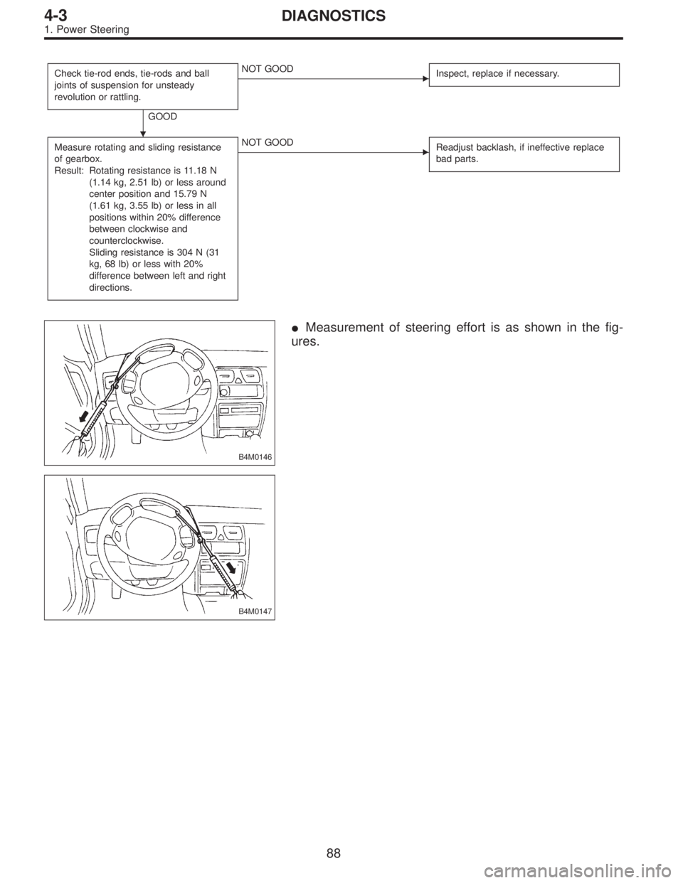
B4M0146
�Measurement of steering effort is as shown in the fig-
ures.
B4M0147
�
88
4-3DIAGNOSTICS
1. Power Steering
Page 830 of 2248
B: REMOVAL
1. ACCELERATOR PEDAL (LHD MODEL)
1) Disconnect ground cable from battery.
2) Disconnect accelerator cable from throttle body.
CAUTION:
Be careful not to kink accelerator cable.
3) Remove instrument panel lower cover from instrument
panel, and connector.
G4M0322
4) Disconnect accelerator cable from accelerator pedal
lever.
G4M0335
5) Working inside engine compartment, remove casing
cap out of the toe board by turning it clockwise.
6) Pull out the cable from the toe board hole.
G4M0321
7) Remove accelerator pedal connecting bolt from accel-
erator pedal bracket.
8
4-5SERVICE PROCEDURE
1. Pedal
Page 832 of 2248
4. ACCELERATOR AND BRAKE PEDAL (RHD
MODEL)
1) Disconnect negative cable from battery.
2) Disconnect accelerator cable from throttle body.
CAUTION:
Be careful not to kink accelerator cable.
3) Remove instrument panel lower cover from instrument
panel.
4) Remove clevis pin which secures brake pedal to brake
booster operating rod. Also disconnect electrical connec-
tors (for stop light switch, etc.).
G4M0322
5) Disconnect accelerator cable from accelerator pedal
lever.
B4M0156A
6) Remove the casing cap out of the toe board by turning
it clockwise.
7) Pull out the cable from the toe board hole.
10
4-5SERVICE PROCEDURE
1. Pedal
Page 840 of 2248
 Disconnect accelerator cable from connector inside
engine compartment first.
G2M0280
2) Remove lock nut from accelerator cable bracket.
3) Separate accelerator cable�
1from bracket, then")
A: REMOVAL
1) Disconnect accelerator cable from connector inside
engine compartment first.
G2M0280
2) Remove lock nut from accelerator cable bracket.
3) Separate accelerator cable�
1from bracket, then unlock
inner cable.
4) Remove cable end from throttle cam using your finger-
tips.
CAUTION:
Be careful not to bend inner cable.
5) Disconnect cable end from accelerator cable bracket
inside driver compartment.
6) Remove clip inside engine compartment.
G4M0335
7) Working inside engine compartment, remove the casing
cap out of the toe board by turning it clockwise.
8) Pull out the cable from the toe board hole.
B: INSTALLATION
1) Installation is in the reverse order of removal proce-
dures.
CAUTION:
�Be careful not to kink accelerator cable.
�Make sure that holder and casing cap are securely
connected.
B4M0159A
�1Casing cap
�
2Accelerator cable
�
3Toe board
�
4Accelerator pedal bracket
�
5Holder
2) Adjustment after cable installation.
18
4-5SERVICE PROCEDURE
3. Accelerator Cable
 5.3 (17.4)
Steering angle (Inside-Outside) 37.6°—32.6°
Steering wheel diameter mm (in) 385 (15.16)
Overall gear ratio")
 Disconnect battery minus terminal.
2) Loosen front wheel nut.
3) Lift vehicle and remove front wheels.
4) Remove front exhaust pipe assembly.
WARNING:
Be careful, exhaust pipe is hot.
G4")
![SUBARU LEGACY 1995 Service Repair Manual G4M0098
7. Pipe Assembly (Power Steering
System) [LHD model]
A: REMOVAL
1) Disconnect battery minus terminal.
G4M0099
2) Lift vehicle and remove jack-up plate.
3) Remove one pipe joint at the center o](/manual-img/17/57432/w960_57432-677.png "SUBARU LEGACY 1995 Service Repair Manual G4M0098
7. Pipe Assembly (Power Steering
System) [LHD model]
A: REMOVAL
1) Disconnect battery minus terminal.
G4M0099
2) Lift vehicle and remove jack-up plate.
3) Remove one pipe joint at the center o")
![SUBARU LEGACY 1995 Service Repair Manual G4M0098
8. Pipe Assembly (Power Steering
System) [RHD model]
A: REMOVAL
1) Disconnect battery negative terminal.
B4M0671A
2) Lift vehicle and remove jack-up plate.
3) Remove one pipe joint at the cent](/manual-img/17/57432/w960_57432-682.png "SUBARU LEGACY 1995 Service Repair Manual G4M0098
8. Pipe Assembly (Power Steering
System) [RHD model]
A: REMOVAL
1) Disconnect battery negative terminal.
B4M0671A
2) Lift vehicle and remove jack-up plate.
3) Remove one pipe joint at the cent")

1) Disconnect ground cable from battery.
2) Disconnect accelerator cable from throttle body.
CAUTION:
Be careful not to kink accelerator cable.
3) Remove in")

1) Disconnect negative cable from battery.
2) Disconnect accelerator cable from throttle body.
CAUTION:
Be careful not to kink accelerator cable.
3) Remove i")