Page 80 of 2248

B2M0084A
B2M0420A
4) Check circlip installation groove on the piston for burr.
If necessary, remove burr from the groove so that piston
pin can lightly move.
5) Check piston pin circlip for distortion, cracks and wear.
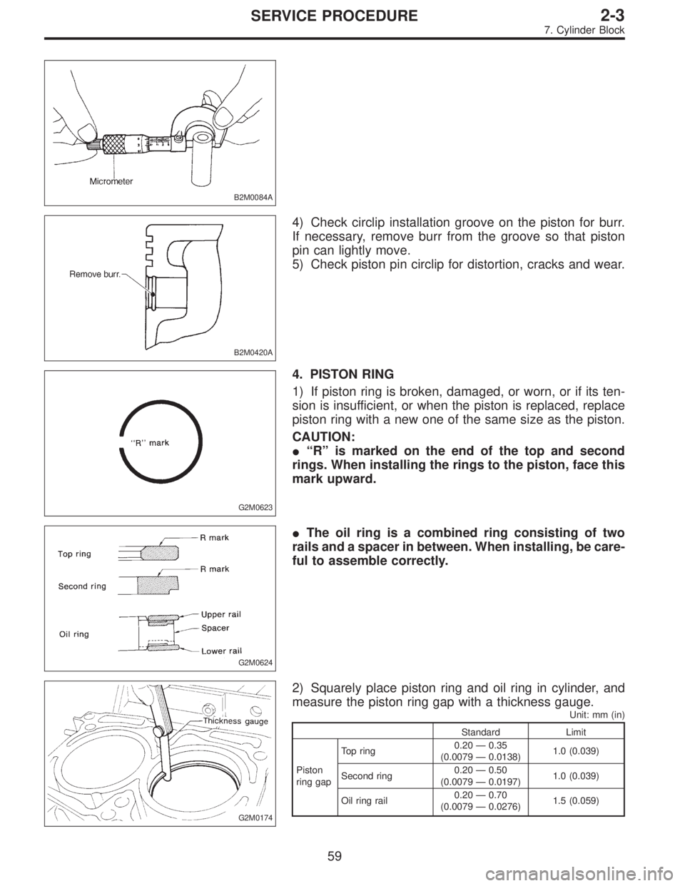
G2M0623
4. PISTON RING
1) If piston ring is broken, damaged, or worn, or if its ten-
sion is insufficient, or when the piston is replaced, replace
piston ring with a new one of the same size as the piston.
CAUTION:
�“R”is marked on the end of the top and second
rings. When installing the rings to the piston, face this
mark upward.
G2M0624
�The oil ring is a combined ring consisting of two
rails and a spacer in between. When installing, be care-
ful to assemble correctly.
G2M0174
2) Squarely place piston ring and oil ring in cylinder, and
measure the piston ring gap with a thickness gauge.
Unit: mm (in)
Standard Limit
Piston
ring gapTop ring0.20—0.35
(0.0079—0.0138)1.0 (0.039)
Second ring0.20—0.50
(0.0079—0.0197)1.0 (0.039)
Oil ring rail0.20—0.70
(0.0079—0.0276)1.5 (0.059)
59
2-3SERVICE PROCEDURE
7. Cylinder Block
Page 100 of 2248
Type of sound Condition Possible cause
Hissing sound—�Loss of compression
�Air leakage in air intake system, hoses, connections or
manifolds
Timing belt noise—�Loose timing belt
�Belt contacting case/adjacent part
NOTE*:
When disconnecting fuel injector connector, Malfunction Indicator Light (CHECK ENGINE light) illuminates and trouble code is stored in
ECM memory.
Therefore, carry out the CLEAR MEMORY MODE and INSPECTION MODE after connecting fuel injector connector. (Ref. to 2-7 On-Board
Diagnostics II System.)
79
2-3DIAGNOSTICS
2. Engine Noise
Page 101 of 2248

1. Lubrication System
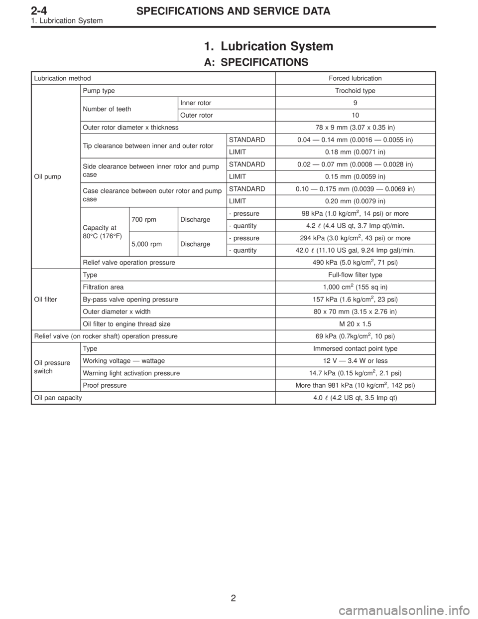
A: SPECIFICATIONS
Lubrication methodForced lubrication
Oil pumpPump typeTrochoid type
Number of teethInner rotor 9
Outer rotor 10
Outer rotor diameter x thickness 78x9mm(3.07 x 0.35 in)
Tip clearance between inner and outer rotorSTANDARD 0.04 — 0.14 mm (0.0016 — 0.0055 in)
LIMIT 0.18 mm (0.0071 in)
Side clearance between inner rotor and pump
caseSTANDARD 0.02 — 0.07 mm (0.0008 — 0.0028 in)
LIMIT 0.15 mm (0.0059 in)
Case clearance between outer rotor and pump
caseSTANDARD 0.10 — 0.175 mm (0.0039 — 0.0069 in)
LIMIT 0.20 mm (0.0079 in)
Capacity at
80°C (176°F)700 rpm Discharge- pressure 98 kPa (1.0 kg/cm
2, 14 psi) or more
- quantity 4.2�(4.4 US qt, 3.7 Imp qt)/min.
5,000 rpm Discharge- pressure 294 kPa (3.0 kg/cm
2, 43 psi) or more
- quantity 42.0�(11.10 US gal, 9.24 Imp gal)/min.
Relief valve operation pressure 490 kPa (5.0 kg/cm
2, 71 psi)
Oil filterTypeFull-flow filter type
Filtration area 1,000 cm
2(155 sq in)
By-pass valve opening pressure 157 kPa (1.6 kg/cm
2, 23 psi)
Outer diameter x width 80 x 70 mm (3.15 x 2.76 in)
Oil filter to engine thread size M 20 x 1.5
Relief valve (on rocker shaft) operation pressure 69 kPa (0.7kg/cm
2, 10 psi)
Oil pressure
switchTypeImmersed contact point type
Working voltage — wattage 12 V — 3.4 W or less
Warning light activation pressure 14.7 kPa (0.15 kg/cm
2, 2.1 psi)
Proof pressure More than 981 kPa (10 kg/cm
2, 142 psi)
Oil pan capacity4.0�(4.2 US qt, 3.5 Imp qt)
2
2-4SPECIFICATIONS AND SERVICE DATA
1. Lubrication System
Page 116 of 2248

1. Engine Lubrication System
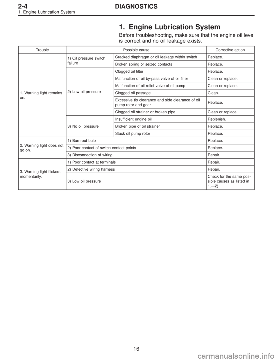
Before troubleshooting, make sure that the engine oil level
is correct and no oil leakage exists.
Trouble Possible cause Corrective action
1. Warning light remains
on.1) Oil pressure switch
failureCracked diaphragm or oil leakage within switch Replace.
Broken spring or seized contacts Replace.
2) Low oil pressureClogged oil filter Replace.
Malfunction of oil by-pass valve of oil filter Clean or replace.
Malfunction of oil relief valve of oil pump Clean or replace.
Clogged oil passage Clean.
Excessive tip clearance and side clearance of oil
pump rotor and gearReplace.
Clogged oil strainer or broken pipe Clean or replace.
3) No oil pressureInsufficient engine oil Replenish.
Broken pipe of oil strainer Replace.
Stuck oil pump rotor Replace.
2. Warning light does not
go on.1) Burn-out bulb Replace.
2) Poor contact of switch contact points Replace.
3) Disconnection of wiring Repair.
3. Warning light flickers
momentarily.1) Poor contact at terminals Repair.
2) Defective wiring harness Repair.
3) Low oil pressureCheck for the same pos-
sible causes as listed in
1.—2)
16
2-4DIAGNOSTICS
1. Engine Lubrication System
Page 129 of 2248
B2M0320
8) Remove radiator upper brackets.
NOTE:
Place left upper radiator bracket between grille and body.
9) While slightly lifting radiator, slide it to left.
G2M0220
10) Lift radiator up and away from vehicle.
B2M0307A
B: INSTALLATION
1) Attach radiator mounting cushions to body.
G2M0220
2) Install radiator while fitting radiator pins to cushions.
13
2-5SERVICE PROCEDURE
4. Radiator
Page 227 of 2248

B2M0173A
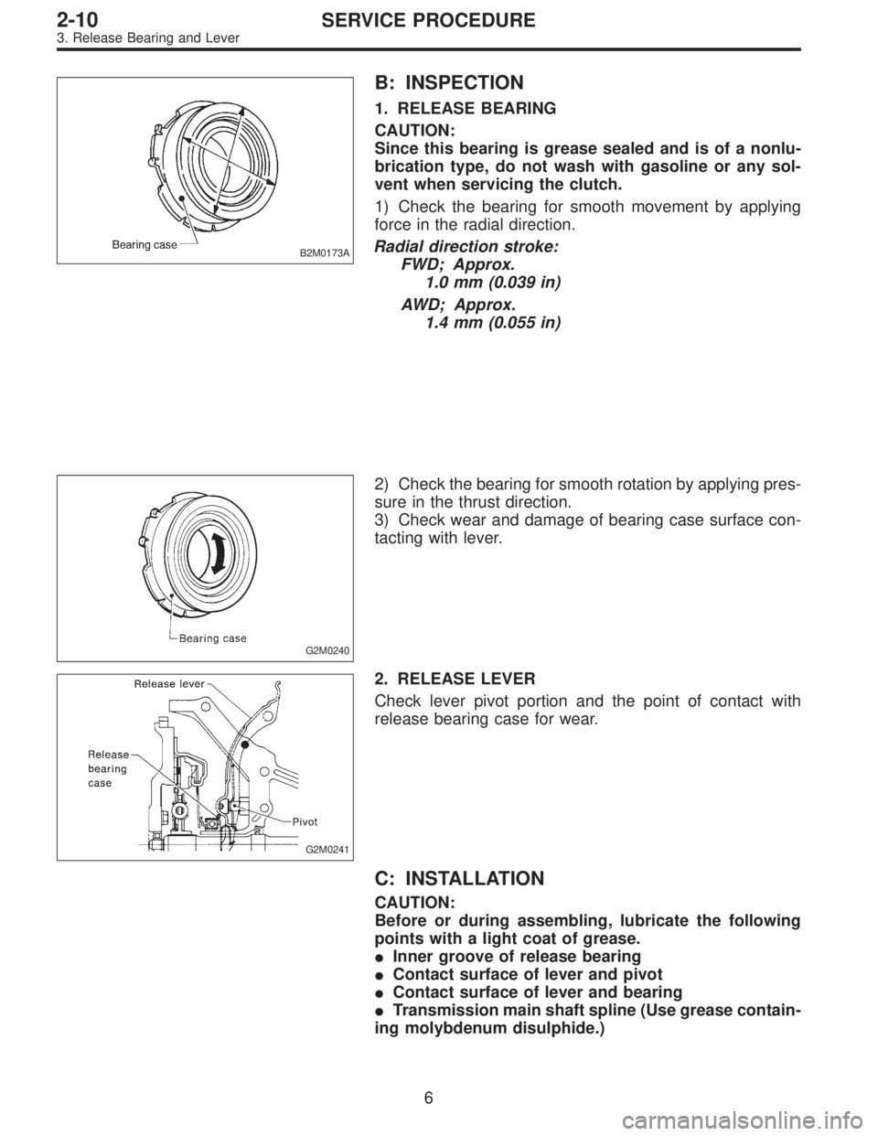
B: INSPECTION
1. RELEASE BEARING
CAUTION:
Since this bearing is grease sealed and is of a nonlu-
brication type, do not wash with gasoline or any sol-
vent when servicing the clutch.
1) Check the bearing for smooth movement by applying
force in the radial direction.
Radial direction stroke:
FWD; Approx.
1.0 mm (0.039 in)
AWD; Approx.
1.4 mm (0.055 in)
G2M0240
2) Check the bearing for smooth rotation by applying pres-
sure in the thrust direction.
3) Check wear and damage of bearing case surface con-
tacting with lever.
G2M0241
2. RELEASE LEVER
Check lever pivot portion and the point of contact with
release bearing case for wear.
C: INSTALLATION
CAUTION:
Before or during assembling, lubricate the following
points with a light coat of grease.
�Inner groove of release bearing
�Contact surface of lever and pivot
�Contact surface of lever and bearing
�Transmission main shaft spline (Use grease contain-
ing molybdenum disulphide.)
6
2-10SERVICE PROCEDURE
3. Release Bearing and Lever
Page 251 of 2248
G2M0299
20) Remove bolts which hold upper side of transmission to
engine.
G2M0300
21) Remove engine from vehicle.
(1) Slightly raise engine.
(2) Raise transmission with garage jack.
(3) Move engine horizontally until mainshaft is with-
drawn from clutch cover.
(4) Slowly move engine away from engine compart-
ment.
CAUTION:
Be careful not to damage adjacent parts or body pan-
els with crank pulley, oil pressure gauge, etc.
17
2-11SERVICE PROCEDURE
2. Engine
Page 261 of 2248
G2M0266
1) Open front hood fully, and support with stay.
2) Disconnect battery ground terminal.
3) Remove air intake duct.
G2M0544
4) Disconnect connectors and cables.
(1) Disconnect the following connectors.
�Front oxygen sensor connector
G2M0307
�Transmission harness connector
�Transmission ground terminal
B2M0337
�Neutral position switch connector (MT model)
�Back-up light switch connector (MT model)
G2M0827
�Vehicle speed sensor 2
27
2-11SERVICE PROCEDURE
3. Transmission