Page 1552 of 2248
OBD0516
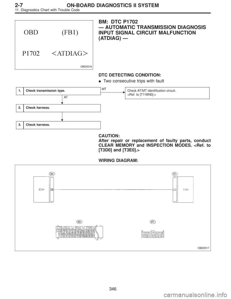
BM: DTC P1702
—AUTOMATIC TRANSMISSION DIAGNOSIS
INPUT SIGNAL CIRCUIT MALFUNCTION
(ATDIAG)—
DTC DETECTING CONDITION:
�Two consecutive trips with fault
1.Check transmission type.
AT
�MT
Check AT/MT identification circuit.
2.Check harness.
3.Check harness.
CAUTION:
After repair or replacement of faulty parts, conduct
CLEAR MEMORY and INSPECTION MODES.
[T3D0] and [T3E0].>
WIRING DIAGRAM:
OBD0517
�
�
346
2-7ON-BOARD DIAGNOSTICS II SYSTEM
11. Diagnostics Chart with Trouble Code
Page 1554 of 2248
BN:—AT/MT IDENTIFICATION CIRCUIT
MALFUNCTION [MT VEHICLES]—
DESCRIPTION:
The circuit allows the ECM to identify the vehicle as an AT
or MT vehicle.
1.Check harness connector.
CAUTION:
After repair or replacement of faulty parts, conduct
CLEAR MEMORY and INSPECTION MODES.
[T3D0] and [T3E0].>
WIRING DIAGRAM:
OBD0521
OBD0522A
1
CHECK HARNESS CONNECTOR.
1) Turn ignition switch to ON.
2) Measure voltage between ECM and body.
: Connector & terminal
(B84) No. 50—Body / 2 V, or more
: Repair open circuit of harness between ECM con-
nector and body.
: Confirm good connection at ECM connector.
348
2-7ON-BOARD DIAGNOSTICS II SYSTEM
11. Diagnostics Chart with Trouble Code
Page 1888 of 2248
1. General Description
1. HOW TO USE THIS MANUAL
The description of the electrical system is divided into the
charging system, starting system, etc.
1) First, open to the necessary electrical system section
and wiring diagram.
2) Next, open the foldout page of the electrical wiring dia-
gram. By observing the electrical wiring harness’ illustra-
tions (front, instrument panel, etc.), the wiring diagram con-
nector can be located.
G6M0192
G6M0193
2. WIRING DIAGRAM
The wiring diagram of each system is illustrated so that you
can understand the path through which the electric current
flows from the battery.
Sketches and codes are used in the diagrams. They should
read as follows:
1) Each connector and its terminal position are indicated
by a sketch of the connector in a disconnected state which
is viewed from the front, as shown in figure.
2
6-3WIRING DIAGRAM
1. General Description
Page 1889 of 2248
 The number of poles or pins, presence of a lock, and pin
number of each terminal are indicated in the sketch of each
connector.
In the sketch, the highest pole number refers to the num-
ber of pole")
2) The number of poles or pins, presence of a lock, and pin
number of each terminal are indicated in the sketch of each
connector.
In the sketch, the highest pole number refers to the num-
ber of poles which the connector has. For example, the
sketch of the connector shown in figure indicates the con-
nector has 9 poles.
Connector used in vehicleConnector shown in wiring diagram
Sketch Symbol Number of poles
G6M0194G6M0196
G6M0198
Numbered in order from
upper right to lower left.
G6M0195G6M0197
Numbered in order from
upper left to lower right.
G6M0199
When one set of connectors is viewed from the front side,
the pole numbers of one connector are symmetrical to
those of the other. When these two connectors are con-
nected as a unit, the poles which have the same number
are joined.
3) Electrical wiring harness
The connectors are numbered along with the number of
poles, external colors, and mating connections in the
accompanying list.
3
6-3WIRING DIAGRAM
1. General Description
Page 1890 of 2248
 The sketch of each connector in the wiring diagram
usually shows the“A”side of the connector. The relation-
ship between the wire color, terminal number and connec-
tor is described in")
G6M0200
4) The sketch of each connector in the wiring diagram
usually shows the“A”side of the connector. The relation-
ship between the wire color, terminal number and connec-
tor is described in figure.
NOTE:
A wire which runs in one direction from a connector termi-
nal sometimes may have a different color from that which
runs in the other direction from that terminal.
G6M0216
5) In wiring diagram, connectors which have no terminal
number refer to one-pole types. Sketches of these connec-
tors are omitted intentionally.
G6M0201
6) The following color codes are used to indicate the col-
ors of the wires used.
Color code Color
L Blue
B Black
Y Yellow
G Green
RRed
W White
Br Brown
Lg Light green
Gr Gray
P Pink
Or Orange
Lb Light Blue
V Violet
SA Sealed (Inner)
SB Sealed (Outer)
G6M0202
7) The wire color code, which consists of two letters (or
three letters including Br or Lg), indicates the standard
color (base color of the wire covering) by its first letter and
the stripe marking by its second letter.
4
6-3WIRING DIAGRAM
1. General Description
Page 1891 of 2248
 The table below lists the nominal sectional areas and
allowable currents of the wires.
Nominal
sectional area
mm
2
No. of strands/
strand diameterOutside
diameter of
finished wiring
mmAllowable
cur")
8) The table below lists the nominal sectional areas and
allowable currents of the wires.
Nominal
sectional area
mm
2
No. of strands/
strand diameterOutside
diameter of
finished wiring
mmAllowable
current
Amps/40°C
0.3 7/0.26 1.8 7
0.5 7/0.32 2.2 (or 2.0) 12
0.75 30/0.18 2.6 (or 2.4) 16
0.85 11/0.32 2.4 (or 2.2) 16
1.25 16/0.32 2.7 (or 2.5) 21
2 26/0.32 3.1 (or 2.9) 28
3 41/0.32 3.8 (or 3.6) 38
5 65/0.32 4.6 (or 4.4) 51
8 50/0.45 5.5 67
CAUTION:
When replacing or repairing a wire, be sure to use the
same size and type of the wire which was originally
used.
NOTE:
�The allowable current in the above table indicates the
tolerable amperage of each wire at an ambient tempera-
ture of 40°C (104°F).
�The allowable current changes with ambient tempera-
ture. Also, it changes if a bundle of more than two wires is
used.
G6M0203
9) Each unit is directly grounded to the body or indirectly
grounds through a harness ground terminal. Different sym-
bols are used in the wiring diagram to identify the two
grounding systems.
The ground points shown in the wiring diagram refer to the
following:
�GBBody ground
�GEEngine ground
�GRRadio ground
�GDRear defogger ground
All wiring harnesses are provided with a ground point which
should be securely connected.
5
6-3WIRING DIAGRAM
1. General Description
Page 1892 of 2248
10) Relays are classified as normally-open or normally-
closed.
The normally-closed relay has one or more contacts.
The wiring diagram shows the relay mode when the ener-
gizing circuit is OFF.
G6M0204
Key to symbols:
�→: Current flows.
X→: Current does not flow.
6
6-3WIRING DIAGRAM
1. General Description
Page 1893 of 2248
G6M0205
11) Each connector number shown in the wiring diagram
corresponds to that in the wiring harness. The location of
each connector in the actual vehicle is determined by read-
ing the first character of the connector (for example, a“F”
for F8,“i”for i16, etc.) and the type of wiring harness.
The first character of each connector number refers to the
area or system of the vehicle, as indicated in table below.
Symbol Wiring harness and Cord
F Front wiring harness
B Bulkhead wiring harness
E Engine wiring harness
T Transmission cord
D Door cord LH & RH, Rear gate cord
I Instrument panel wiring harness
RRear wiring harness, Rear defogger cord
Room light cord,
Fuel tank cord,
Sunroof cord,
Trunk lid cord
P Floor wiring harness
7
6-3WIRING DIAGRAM
1. General Description
![SUBARU LEGACY 1995 Service Repair Manual BN:—AT/MT IDENTIFICATION CIRCUIT
MALFUNCTION [MT VEHICLES]—
DESCRIPTION:
The circuit allows the ECM to identify the vehicle as an AT
or MT vehicle.
1.Check harness connector.
CAUTION:
After repair](/manual-img/17/57432/w960_57432-1553.png "SUBARU LEGACY 1995 Service Repair Manual BN:—AT/MT IDENTIFICATION CIRCUIT
MALFUNCTION [MT VEHICLES]—
DESCRIPTION:
The circuit allows the ECM to identify the vehicle as an AT
or MT vehicle.
1.Check harness connector.
CAUTION:
After repair")
 First, open to the necessary electrical system s")
 Relays are classified as normally-open or normally-
closed.
The normally-closed relay has one or more contacts.
The wiring diagram shows the relay mode when the ener-
gizing circuit is OFF.
G6M020")
 Each connector number shown in the wiring diagram
corresponds to that in the wiring harness. The location of
each connector in the actual vehicle is determined by read-
ing the first chara")