Page 1510 of 2248
WIRING DIAGRAM:
OBD0613
1CHECK ANY OTHER DTC (BESIDES DTC
P0760) ON DISPLAY.
: Is there any other DTC on display?
: Inspect relevant DTC using“11. Diagnostics Chart
with Trouble Code”.
: Go to step 2.
2
CHECK INHIBITOR SWITCH CIRCUIT.
: Is there any trouble in inhibitor switch cir-
cuit?
: Repair or replace inhibitor switch circuit.
: Go to step 3.
OBD0145A
3
CHECK GEAR POSITION.
1) Turn ignition switch to OFF.
2) Connect the Subaru select monitor to data link connec-
tor.
304
2-7ON-BOARD DIAGNOSTICS II SYSTEM
11. Diagnostics Chart with Trouble Code
Page 1514 of 2248
1.Check harness connector between TCM and
shift solenoid 3.
2.Check shift solenoid 3’s ground line.
3.Check shift solenoid 3.
4.Check output signal emitted from TCM.
CAUTION:
After repair or replacement of faulty parts, conduct
CLEAR MEMORY and INSPECTION MODES.
[T3D0] and [T3E0].>
WIRING DIAGRAM:
OBD0452
NOTE:
For the diagnostic procedure on shift solenoid 3 circuit,
refer to“3-2 [T7C0]”.
�
�
�
308
2-7ON-BOARD DIAGNOSTICS II SYSTEM
11. Diagnostics Chart with Trouble Code
Page 1515 of 2248
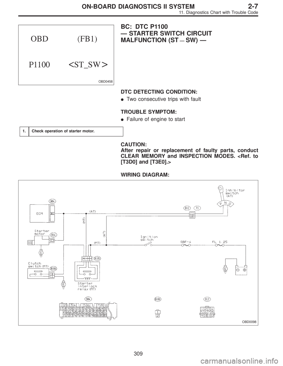
OBD0458
BC: DTC P1100
—STARTER SWITCH CIRCUIT
MALFUNCTION (ST
—SW)—
DTC DETECTING CONDITION:
�Two consecutive trips with fault
TROUBLE SYMPTOM:
�Failure of engine to start
1.Check operation of starter motor.
CAUTION:
After repair or replacement of faulty parts, conduct
CLEAR MEMORY and INSPECTION MODES.
[T3D0] and [T3E0].>
WIRING DIAGRAM:
OBD0098
309
2-7ON-BOARD DIAGNOSTICS II SYSTEM
11. Diagnostics Chart with Trouble Code
Page 1518 of 2248
WIRING DIAGRAM:
OBD0467
OBD0468A
1
CHECK INPUT SIGNAL FOR ECM.
1) Turn ignition switch to ON.
2) Measure voltage between ECM and body.
: Connector & terminal
(B84) No. 78—Body / 5.0±0.5 V (Neutral
position)
(B84) No. 78—Body / 0 V (Other positions)
: Go to next.
: Go to step 2.
: Is there poor contact in ECM connector?
: Repair poor contact in ECM connector.
: Replace ECM with a new one.
312
2-7ON-BOARD DIAGNOSTICS II SYSTEM
11. Diagnostics Chart with Trouble Code
Page 1522 of 2248
WIRING DIAGRAM:
B2M0629
OBD0468A
1
CHECK INPUT SIGNAL FOR ECM.
1) Turn ignition switch to ON.
2) Measure voltage between ECM and body.
: Connector & terminal
(B84) No. 78—Body / 0 V (“N”and“P”
positions)
(B84) No. 78—Body / 5.0±0.5 V
(Other positions)
Go to next.
: Go to step 2.
: Is there poor contact in ECM connector?
: Repair poor contact in ECM connector.
: Replace ECM with a new one.
316
2-7ON-BOARD DIAGNOSTICS II SYSTEM
11. Diagnostics Chart with Trouble Code
Page 1526 of 2248
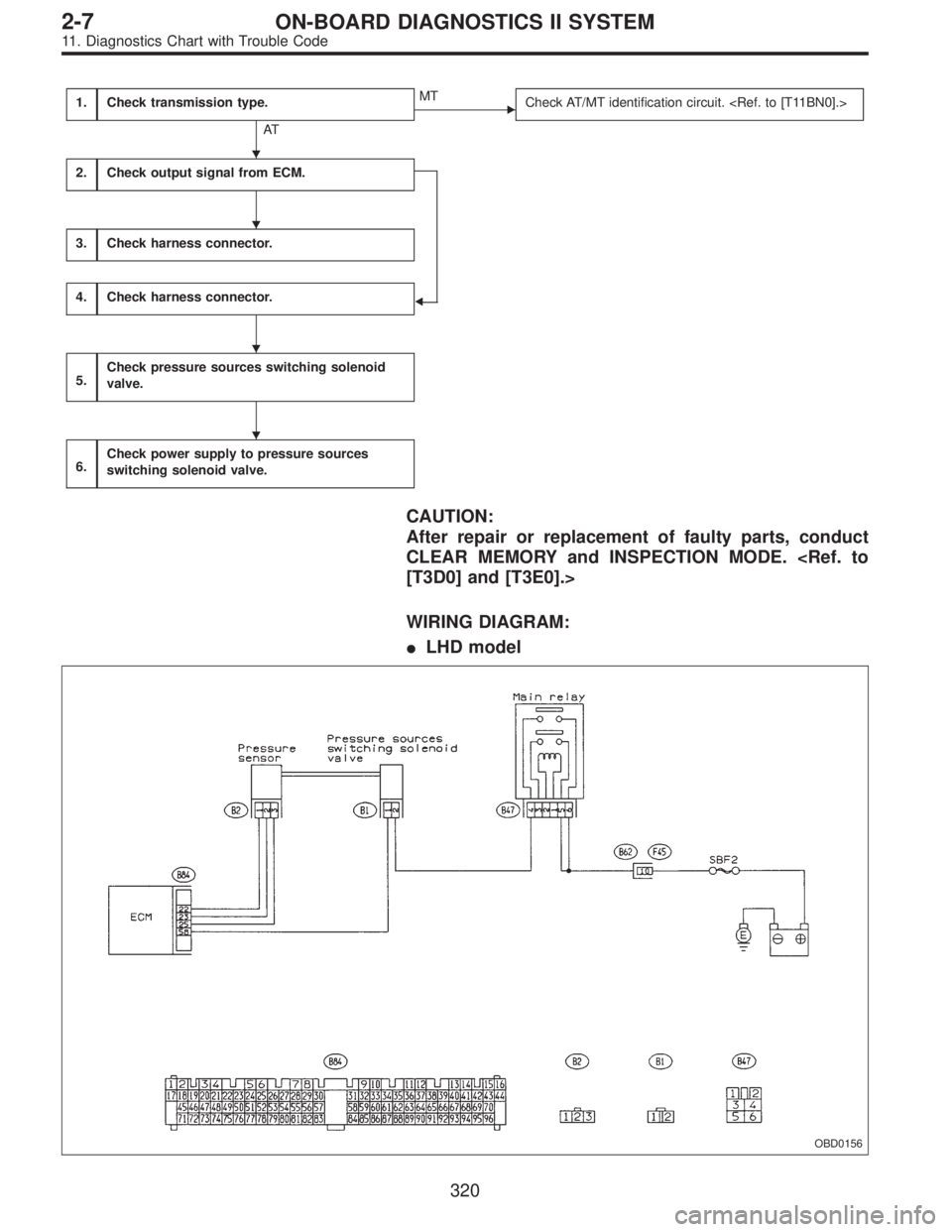
1.Check transmission type.
AT
�MT
Check AT/MT identification circuit.
2.Check output signal from ECM.
�
3.Check harness connector.
4.Check harness connector.
5.Check pressure sources switching solenoid
valve.
6.Check power supply to pressure sources
switching solenoid valve.
CAUTION:
After repair or replacement of faulty parts, conduct
CLEAR MEMORY and INSPECTION MODE.
[T3D0] and [T3E0].>
WIRING DIAGRAM:
�LHD model
OBD0156
�
�
�
�
320
2-7ON-BOARD DIAGNOSTICS II SYSTEM
11. Diagnostics Chart with Trouble Code
Page 1527 of 2248
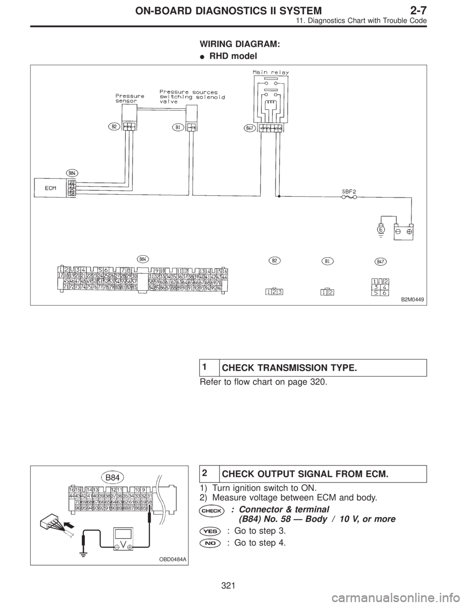
WIRING DIAGRAM:
�RHD model
B2M0449
1
CHECK TRANSMISSION TYPE.
Refer to flow chart on page 320.
OBD0484A
2
CHECK OUTPUT SIGNAL FROM ECM.
1) Turn ignition switch to ON.
2) Measure voltage between ECM and body.
: Connector & terminal
(B84) No. 58—Body / 10 V, or more
: Go to step 3.
: Go to step 4.
321
2-7ON-BOARD DIAGNOSTICS II SYSTEM
11. Diagnostics Chart with Trouble Code
Page 1531 of 2248
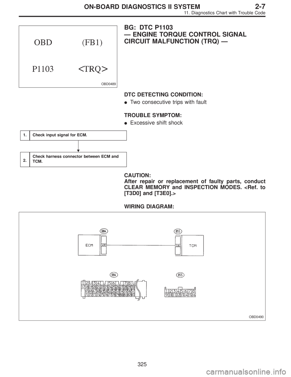
OBD0489
BG: DTC P1103
—ENGINE TORQUE CONTROL SIGNAL
CIRCUIT MALFUNCTION (TRQ)—
DTC DETECTING CONDITION:
�Two consecutive trips with fault
TROUBLE SYMPTOM:
�Excessive shift shock
1.Check input signal for ECM.
2.Check harness connector between ECM and
TCM.
CAUTION:
After repair or replacement of faulty parts, conduct
CLEAR MEMORY and INSPECTION MODES.
[T3D0] and [T3E0].>
WIRING DIAGRAM:
OBD0490
�
325
2-7ON-BOARD DIAGNOSTICS II SYSTEM
11. Diagnostics Chart with Trouble Code
 ON DISPLAY.
: Is there any other DTC on display?
: Inspect relevant DTC using“11. Diagnostics Chart
with Trouble Code”.
: Go to ste")

 Turn ignition switch to ON.
2) Measure voltage between ECM and body.
: Connector & terminal
(B84) No. 78—Body / 5.0±0.5 V (Neutral")
 Turn ignition switch to ON.
2) Measure voltage between ECM and body.
: Connector & terminal
(B84) No. 78—Body / 0 V (“N”and“P�")