Page 1442 of 2248
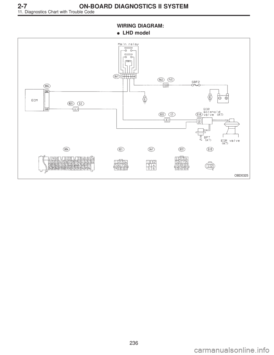
WIRING DIAGRAM:
�LHD model
OBD0325
236
2-7ON-BOARD DIAGNOSTICS II SYSTEM
11. Diagnostics Chart with Trouble Code
Page 1443 of 2248
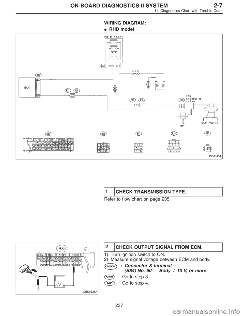
WIRING DIAGRAM:
�RHD model
B2M0454
1
CHECK TRANSMISSION TYPE.
Refer to flow chart on page 235.
OBD0326A
2
CHECK OUTPUT SIGNAL FROM ECM.
1) Turn ignition switch to ON.
2) Measure signal voltage between ECM and body.
: Connector & terminal
(B84) No. 60—Body / 10 V, or more
: Go to step 3.
: Go to step 4.
237
2-7ON-BOARD DIAGNOSTICS II SYSTEM
11. Diagnostics Chart with Trouble Code
Page 1447 of 2248
1.Check any other DTC P0130, P0133, P0135,
P0136, P0139 and P0141 on display.
2.Check exhaust system.
3.Check rear catalytic converter.
CAUTION:
After repair or replacement of faulty parts, conduct
CLEAR MEMORY and INSPECTION MODES.
[T3D0] and [T3E0].>
WIRING DIAGRAM:
�LHD model
B2M0626
�
�
241
2-7ON-BOARD DIAGNOSTICS II SYSTEM
11. Diagnostics Chart with Trouble Code
Page 1448 of 2248
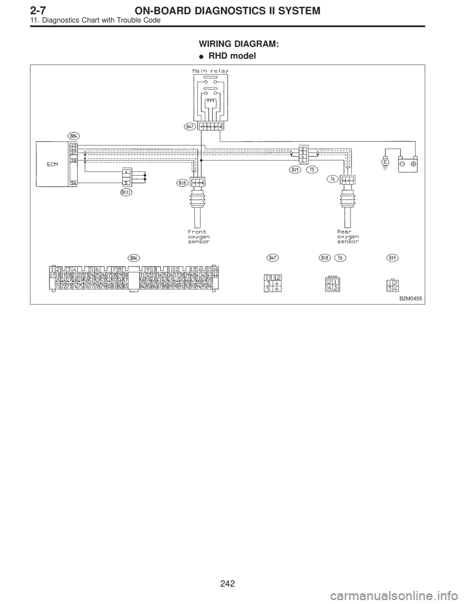
WIRING DIAGRAM:
�RHD model
B2M0455
242
2-7ON-BOARD DIAGNOSTICS II SYSTEM
11. Diagnostics Chart with Trouble Code
Page 1451 of 2248
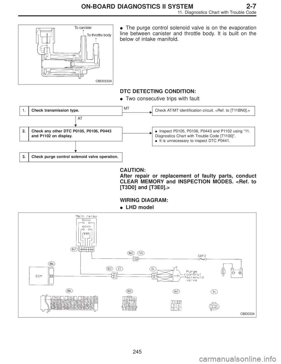
OBD0333A
�The purge control solenoid valve is on the evaporation
line between canister and throttle body. It is built on the
below of intake manifold.
DTC DETECTING CONDITION:
�Two consecutive trips with fault
1.Check transmission type.
AT
�MT
Check AT/MT identification circuit.
2.Check any other DTC P0105, P0106, P0443
and P1102 on display.��Inspect P0105, P0106, P0443 and P1102 using“11 .
Diagnostics Chart with Trouble Code [T1100]”.
�It is unnecessary to inspect DTC P0441.
3.Check purge control solenoid valve operation.
CAUTION:
After repair or replacement of faulty parts, conduct
CLEAR MEMORY and INSPECTION MODES.
[T3D0] and [T3E0].>
WIRING DIAGRAM:
�LHD model
OBD0334
�
�
245
2-7ON-BOARD DIAGNOSTICS II SYSTEM
11. Diagnostics Chart with Trouble Code
Page 1452 of 2248
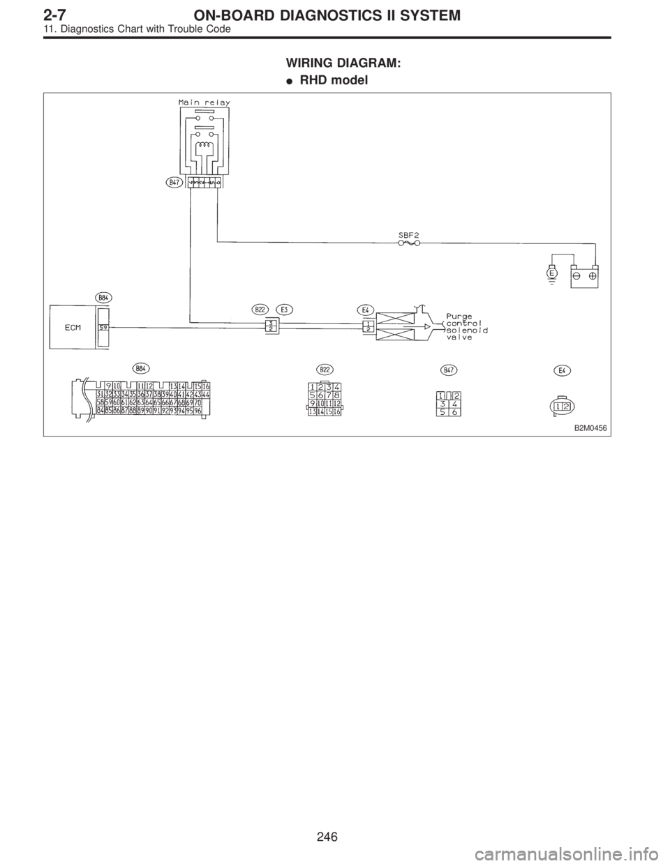
WIRING DIAGRAM:
�RHD model
B2M0456
246
2-7ON-BOARD DIAGNOSTICS II SYSTEM
11. Diagnostics Chart with Trouble Code
Page 1455 of 2248
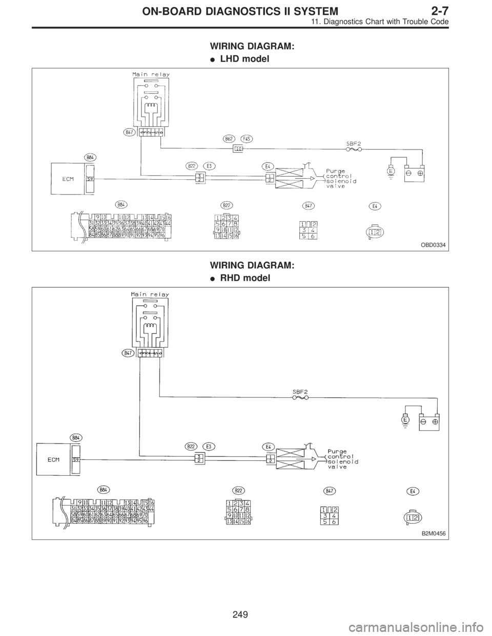
WIRING DIAGRAM:
�LHD model
OBD0334
WIRING DIAGRAM:
�RHD model
B2M0456
249
2-7ON-BOARD DIAGNOSTICS II SYSTEM
11. Diagnostics Chart with Trouble Code
Page 1460 of 2248
1.Check speedometer operation in combination
meter.
2.Check harness.
3.Check harness.
CAUTION:
After repair or replacement of faulty parts, conduct
CLEAR MEMORY and INSPECTION MODES.
[T3D0] and [T3E0].>
WIRING DIAGRAM:
OBD0343
�
�
254
2-7ON-BOARD DIAGNOSTICS II SYSTEM
11. Diagnostics Chart with Trouble Code

![SUBARU LEGACY 1995 Service Repair Manual 1.Check speedometer operation in combination
meter.
2.Check harness.
3.Check harness.
CAUTION:
After repair or replacement of faulty parts, conduct
CLEAR MEMORY and INSPECTION MODES. <Ref. to
[T3D0] a](/manual-img/17/57432/w960_57432-1459.png "SUBARU LEGACY 1995 Service Repair Manual 1.Check speedometer operation in combination
meter.
2.Check harness.
3.Check harness.
CAUTION:
After repair or replacement of faulty parts, conduct
CLEAR MEMORY and INSPECTION MODES. <Ref. to
[T3D0] a")