Page 1534 of 2248
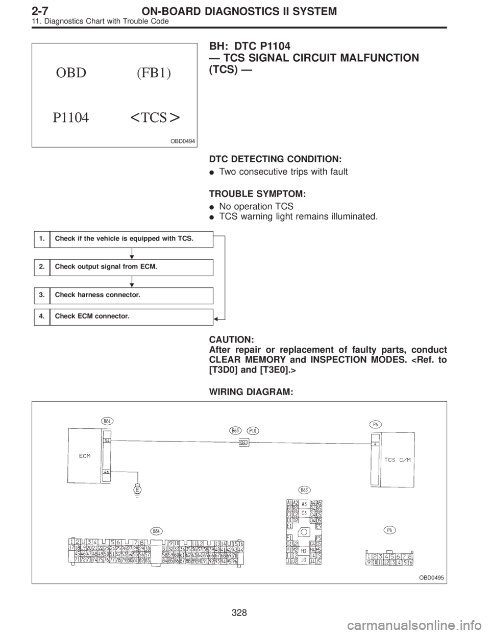
OBD0494
BH: DTC P1104
—TCS SIGNAL CIRCUIT MALFUNCTION
(TCS)—
DTC DETECTING CONDITION:
�Two consecutive trips with fault
TROUBLE SYMPTOM:
�No operation TCS
�TCS warning light remains illuminated.
1.Check if the vehicle is equipped with TCS.
�
2.Check output signal from ECM.
3.Check harness connector.
4.Check ECM connector.
CAUTION:
After repair or replacement of faulty parts, conduct
CLEAR MEMORY and INSPECTION MODES.
[T3D0] and [T3E0].>
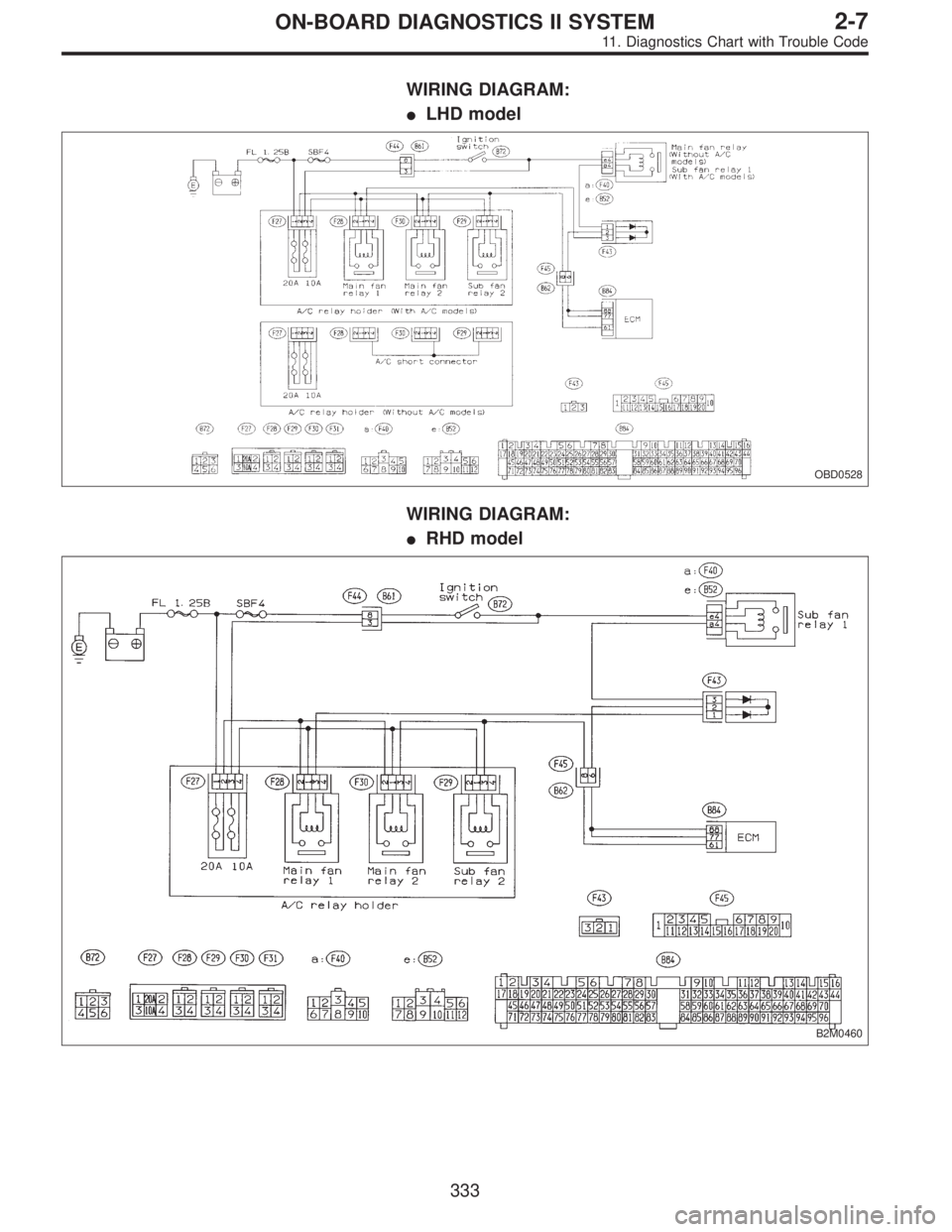
WIRING DIAGRAM:
OBD0495
�
�
328
2-7ON-BOARD DIAGNOSTICS II SYSTEM
11. Diagnostics Chart with Trouble Code
Page 1539 of 2248
WIRING DIAGRAM:
�LHD model
OBD0528
WIRING DIAGRAM:
�RHD model
B2M0460
333
2-7ON-BOARD DIAGNOSTICS II SYSTEM
11. Diagnostics Chart with Trouble Code
Page 1545 of 2248
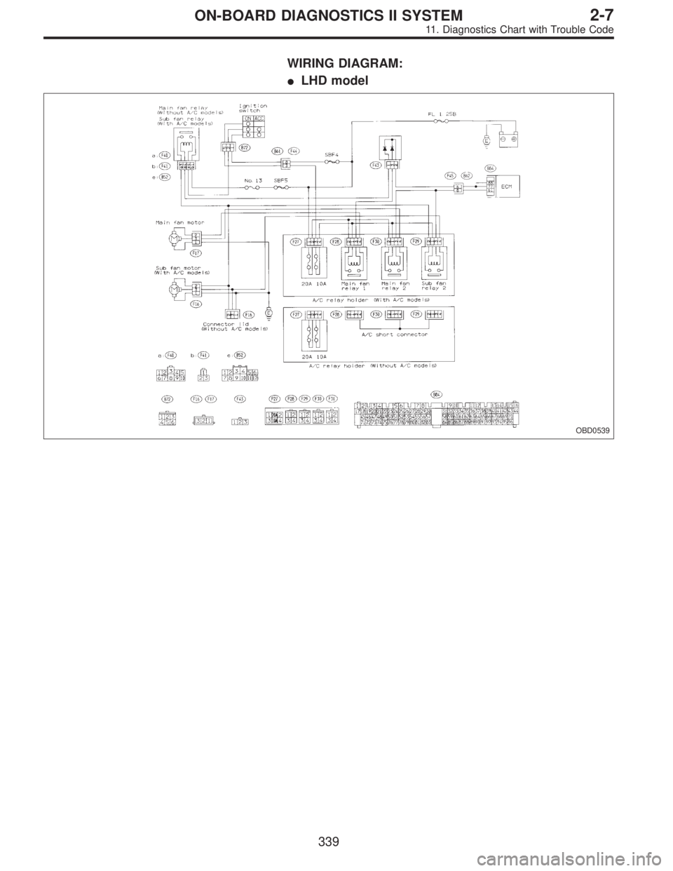
WIRING DIAGRAM:
�LHD model
OBD0539
339
2-7ON-BOARD DIAGNOSTICS II SYSTEM
11. Diagnostics Chart with Trouble Code
Page 1546 of 2248
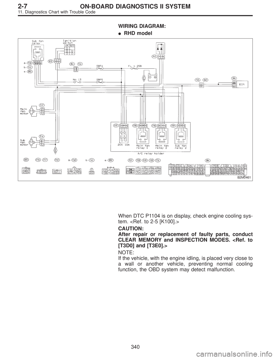
WIRING DIAGRAM:
�RHD model
B2M0461
When DTC P1104 is on display, check engine cooling sys-
tem.
CAUTION:
After repair or replacement of faulty parts, conduct
CLEAR MEMORY and INSPECTION MODES.
[T3D0] and [T3E0].>
NOTE:
If the vehicle, with the engine idling, is placed very close to
a wall or another vehicle, preventing normal cooling
function, the OBD system may detect malfunction.
340
2-7ON-BOARD DIAGNOSTICS II SYSTEM
11. Diagnostics Chart with Trouble Code
Page 1548 of 2248
1.Check harness connector between TCM and
throttle position sensor.
2.Check throttle position sensor.
3.Check input signal for TCM.
4.Check power supply to throttle position
sensor.
CAUTION:
After repair or replacement of faulty parts, conduct
CLEAR MEMORY and INSPECTION MODES.
[T3D0] and [T3E0].>
WIRING DIAGRAM:
OBD0502
NOTE:
For the diagnostic procedure on throttle position sensor
circuit, refer to“3-2 [T7L0]”.
�
�
�
342
2-7ON-BOARD DIAGNOSTICS II SYSTEM
11. Diagnostics Chart with Trouble Code
Page 1550 of 2248
WIRING DIAGRAM:
OBD0512
OBD0514A
1.CHECK HARNESS CONNECTOR BETWEEN
TCM AND CCM.
1) Turn ignition switch to OFF.
2) Disconnect connectors from TCM and CCM.
3) Measure resistance of harness connector between
TCM and CCM.
: Connector & terminal
(B56) No. 3—(B94) No. 3 / 10Ω, or less
: Repair open circuit of harness between TCM con-
nector and CCM connector.
: Go to next step.
OBD0515A
4) Measure resistance of harness connector between
TCM and body.
: Connector & terminal
(B56) No. 3—Body / 1 MΩ, or more
: Repair short circuit of harness between TCM con-
nector and CCM connector.
: Go to step 2.
344
2-7ON-BOARD DIAGNOSTICS II SYSTEM
11. Diagnostics Chart with Trouble Code
Page 1552 of 2248
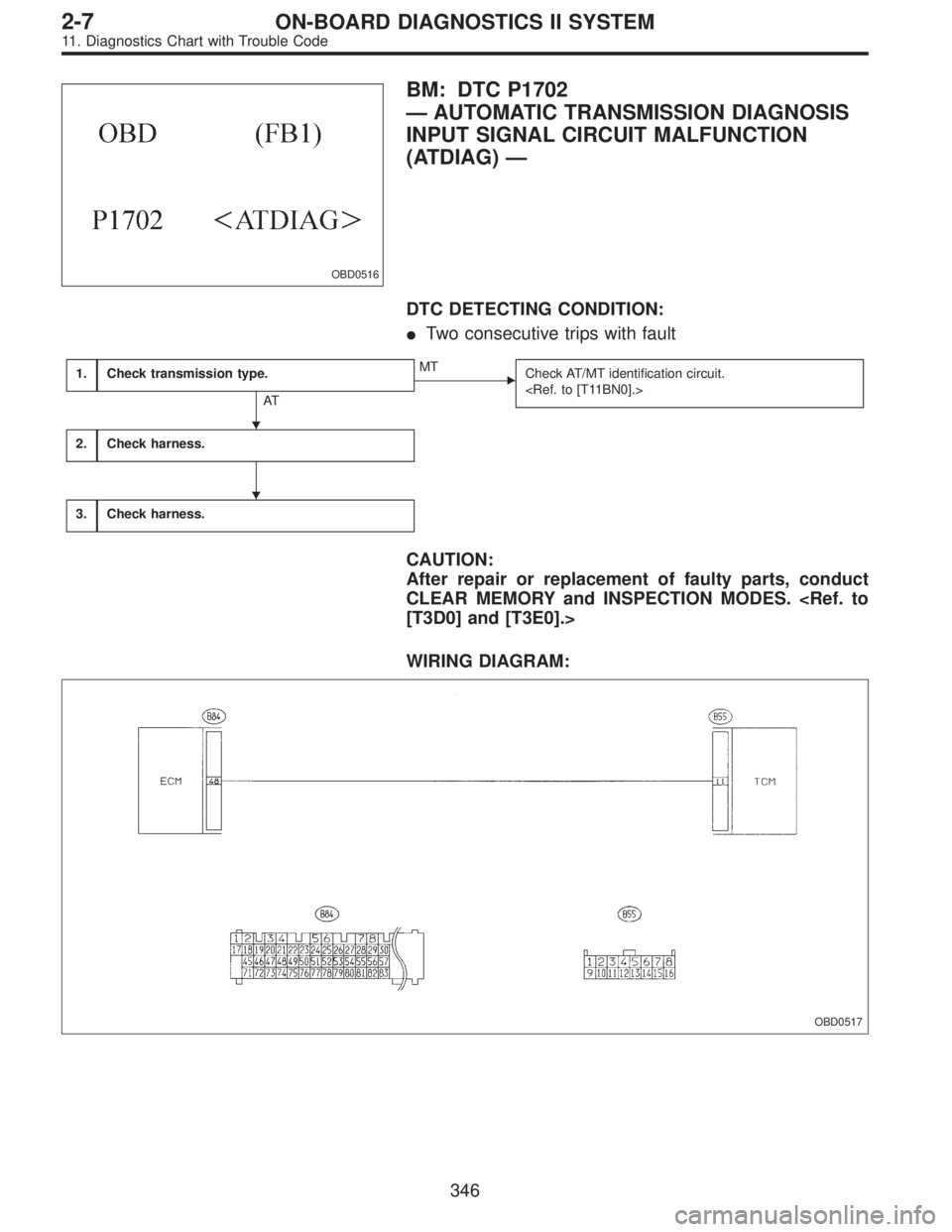
OBD0516
BM: DTC P1702
—AUTOMATIC TRANSMISSION DIAGNOSIS
INPUT SIGNAL CIRCUIT MALFUNCTION
(ATDIAG)—
DTC DETECTING CONDITION:
�Two consecutive trips with fault
1.Check transmission type.
AT
�MT
Check AT/MT identification circuit.
2.Check harness.
3.Check harness.
CAUTION:
After repair or replacement of faulty parts, conduct
CLEAR MEMORY and INSPECTION MODES.
[T3D0] and [T3E0].>
WIRING DIAGRAM:
OBD0517
�
�
346
2-7ON-BOARD DIAGNOSTICS II SYSTEM
11. Diagnostics Chart with Trouble Code
Page 1554 of 2248
BN:—AT/MT IDENTIFICATION CIRCUIT
MALFUNCTION [MT VEHICLES]—
DESCRIPTION:
The circuit allows the ECM to identify the vehicle as an AT
or MT vehicle.
1.Check harness connector.
CAUTION:
After repair or replacement of faulty parts, conduct
CLEAR MEMORY and INSPECTION MODES.
[T3D0] and [T3E0].>
WIRING DIAGRAM:
OBD0521
OBD0522A
1
CHECK HARNESS CONNECTOR.
1) Turn ignition switch to ON.
2) Measure voltage between ECM and body.
: Connector & terminal
(B84) No. 50—Body / 2 V, or more
: Repair open circuit of harness between ECM con-
nector and body.
: Confirm good connection at ECM connector.
348
2-7ON-BOARD DIAGNOSTICS II SYSTEM
11. Diagnostics Chart with Trouble Code

 Turn ignition switch to OFF.
2) Disconnect connectors from TCM and CCM.
3) Measure resistance of harness connector be")
![SUBARU LEGACY 1995 Service Repair Manual BN:—AT/MT IDENTIFICATION CIRCUIT
MALFUNCTION [MT VEHICLES]—
DESCRIPTION:
The circuit allows the ECM to identify the vehicle as an AT
or MT vehicle.
1.Check harness connector.
CAUTION:
After repair](/manual-img/17/57432/w960_57432-1553.png "SUBARU LEGACY 1995 Service Repair Manual BN:—AT/MT IDENTIFICATION CIRCUIT
MALFUNCTION [MT VEHICLES]—
DESCRIPTION:
The circuit allows the ECM to identify the vehicle as an AT
or MT vehicle.
1.Check harness connector.
CAUTION:
After repair")