Page 1463 of 2248
1.Check air intake system.
2.Check output signal from ECM.
�
3.Check idle air control solenoid valve.
4.Check power supply to idle air control
solenoid valve.
5.Check harness connector between ECM and
idle air control solenoid valve.
CAUTION:
After repair or replacement of faulty parts, conduct
CLEAR MEMORY and INSPECTION MODES.
[T3D0] and [T3E0].>
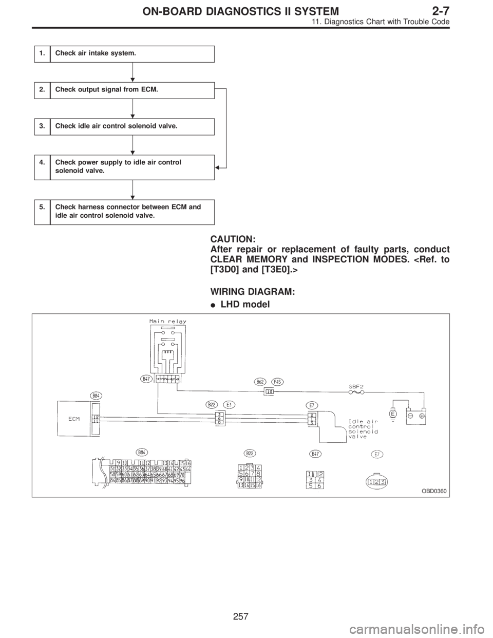
WIRING DIAGRAM:
�LHD model
OBD0360
�
�
�
�
257
2-7ON-BOARD DIAGNOSTICS II SYSTEM
11. Diagnostics Chart with Trouble Code
Page 1464 of 2248
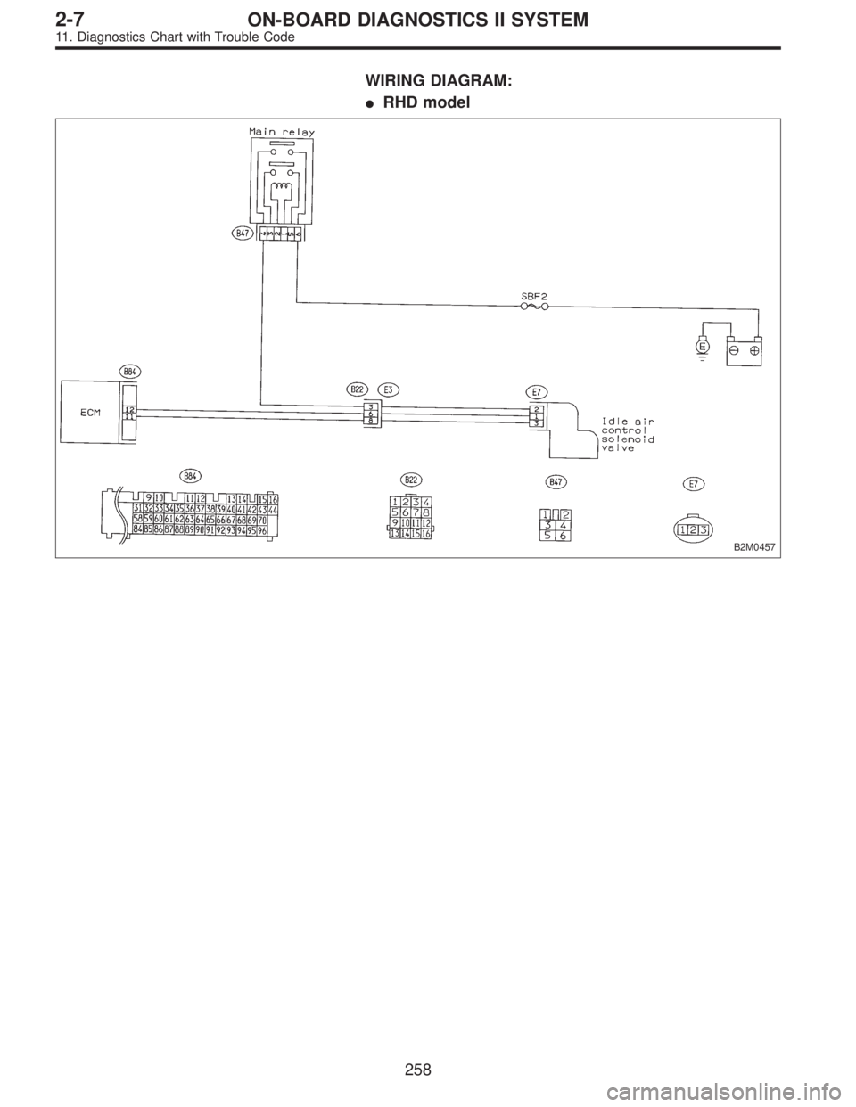
WIRING DIAGRAM:
�RHD model
B2M0457
258
2-7ON-BOARD DIAGNOSTICS II SYSTEM
11. Diagnostics Chart with Trouble Code
Page 1472 of 2248
AK: DTC P0600
—SERIAL COMMUNICATION LINK
MALFUNCTION—
DESCRIPTION:
The serial communication link circuit monitors data com-
munication between scan tool and ECM.
DTC DETECTING CONDITION:
�Two consecutive trips with fault
1.Check harness.
CAUTION:
After repair or replacement of faulty parts, conduct
CLEAR MEMORY and INSPECTION MODES.
[T3D0] and [T3E0].>
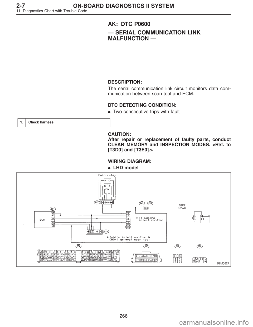
WIRING DIAGRAM:
�LHD model
B2M0627
266
2-7ON-BOARD DIAGNOSTICS II SYSTEM
11. Diagnostics Chart with Trouble Code
Page 1473 of 2248
WIRING DIAGRAM:
�RHD model
B2M0458
OBD0722A
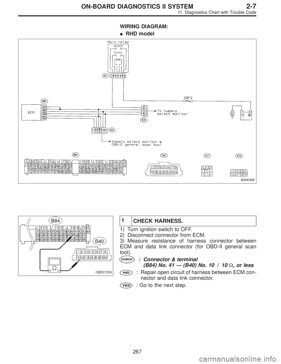
1
CHECK HARNESS.
1) Turn ignition switch to OFF.
2) Disconnect connector from ECM.
3) Measure resistance of harness connector between
ECM and data link connector (for OBD-II general scan
tool).
: Connector & terminal
(B84) No. 41—(B40) No. 10 / 10Ω, or less
: Repair open circuit of harness between ECM con-
nector and data link connector.
: Go to the next step.
267
2-7ON-BOARD DIAGNOSTICS II SYSTEM
11. Diagnostics Chart with Trouble Code
Page 1475 of 2248
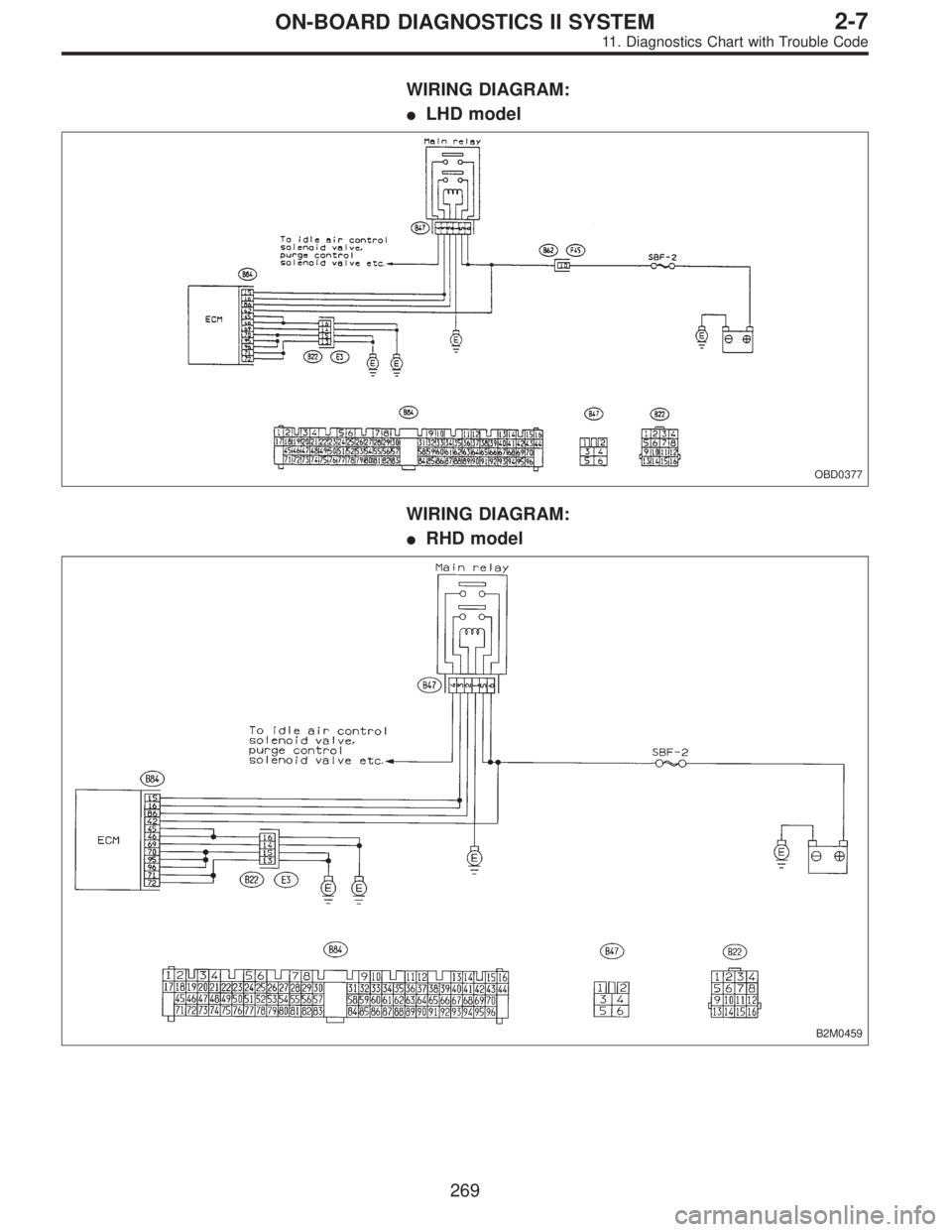
WIRING DIAGRAM:
�LHD model
OBD0377
WIRING DIAGRAM:
�RHD model
B2M0459
269
2-7ON-BOARD DIAGNOSTICS II SYSTEM
11. Diagnostics Chart with Trouble Code
Page 1477 of 2248
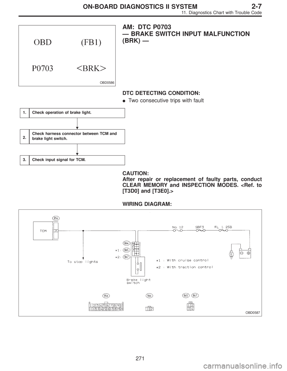
OBD0586
AM: DTC P0703
—BRAKE SWITCH INPUT MALFUNCTION
(BRK)—
DTC DETECTING CONDITION:
�Two consecutive trips with fault
1.Check operation of brake light.
2.Check harness connector between TCM and
brake light switch.
3.Check input signal for TCM.
CAUTION:
After repair or replacement of faulty parts, conduct
CLEAR MEMORY and INSPECTION MODES.
[T3D0] and [T3E0].>
WIRING DIAGRAM:
OBD0587
�
�
271
2-7ON-BOARD DIAGNOSTICS II SYSTEM
11. Diagnostics Chart with Trouble Code
Page 1481 of 2248
1.Check harness connector between TCM and
inhibitor switch.
2.Check inhibitor switch.
3.Check input signal for TCM.
CAUTION:
After repair or replacement of faulty parts, conduct
CLEAR MEMORY and INSPECTION MODES.
[T3D0] and [T3E0].>
WIRING DIAGRAM:
OBD0594
�
�
275
2-7ON-BOARD DIAGNOSTICS II SYSTEM
11. Diagnostics Chart with Trouble Code
Page 1486 of 2248
1.Check harness connector between TCM and
ATF temperature sensor.
2.Check ATF temperature sensor.
3.Check input signal for TCM.
CAUTION:
After repair or replacement of faulty parts, conduct
CLEAR MEMORY and INSPECTION MODES.
[T3D0] and [T3E0].>
WIRING DIAGRAM:
OBD0383
NOTE:
For the diagnostic procedure on transmission fluid tem-
perature sensor circuit, refer to“3-2 [T7G0]”.
�
�
280
2-7ON-BOARD DIAGNOSTICS II SYSTEM
11. Diagnostics Chart with Trouble Code