Page 232 of 2248
 Install flywheel.
2) Install ST, and tighten the flywheel attaching bolts to the
specified torque.
ST 498497100 CRANKSHAFT STOPPER
Tightening torque:
72±3 N⋅m (")
B2M0331A
B2M0332A
C: INSTALLATION
1) Install flywheel.
2) Install ST, and tighten the flywheel attaching bolts to the
specified torque.
ST 498497100 CRANKSHAFT STOPPER
Tightening torque:
72±3 N⋅m (7.3±0.3 kg-m, 52.8±2.2 ft-lb)
NOTE:
Tighten flywheel installing bolts gradually. Each bolt should
be tightened to the specified torque in a crisscross fashion.
G2M0253
3) Insert ST into the clutch disc and install them on the
flywheel by inserting the ST end into the pilot bearing.
ST 499747100 CLUTCH DISC GUIDE
G2M0254
4) Install clutch cover on flywheel and tighten bolts to the
specified torque.
NOTE:
�When installing the clutch cover on the flywheel, position
the clutch cover so that there is a gap of 120°or more
between“0”marks on the flywheel and clutch cover. (“0”
marks indicate the directions of residual unbalance.)
�Note the front and rear of the clutch disc when installing.
�Tighten clutch cover installing bolts gradually. Each bolt
should be tightened to the specified torque in a crisscross
fashion.
Tightening torque:
15.7±1.5 N⋅m (1.6±0.15 kg-m, 11.6±1.1 ft-lb)
5) Remove ST.
ST 499747100 CLUTCH DISC GUIDE
10
2-10SERVICE PROCEDURE
4. Clutch Disc and Cover
Page 235 of 2248
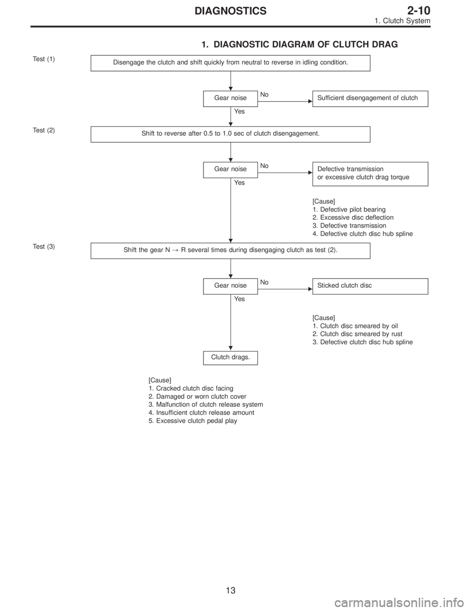
1. DIAGNOSTIC DIAGRAM OF CLUTCH DRAG
Test (1)
Disengage the clutch and shift quickly from neutral to reverse in idling condition.
Gear noise
Ye s
�No
Sufficient disengagement of clutch
Test (2)
Shift to reverse after 0.5 to 1.0 sec of clutch disengagement.
Gear noise
Ye s
�No
Defective transmission
or excessive clutch drag torque
[Cause]
1. Defective pilot bearing
2. Excessive disc deflection
3. Defective transmission
4. Defective clutch disc hub spline
Test (3)
Shift the gear N,R several times during disengaging clutch as test (2).
Gear noise
Ye s
�No
Sticked clutch disc
[Cause]
1. Clutch disc smeared by oil
2. Clutch disc smeared by rust
3. Defective clutch disc hub spline
Clutch drags.
[Cause]
1. Cracked clutch disc facing
2. Damaged or worn clutch cover
3. Malfunction of clutch release system
4. Insufficient clutch release amount
5. Excessive clutch pedal play
�
�
�
�
�
�
13
2-10DIAGNOSTICS
1. Clutch System
Page 236 of 2248
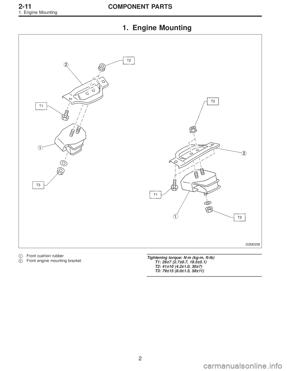
1. Engine Mounting
G2M0258
�1Front cushion rubber
�
2Front engine mounting bracketTightening torque: N⋅m (kg-m, ft-lb)
T1: 26±7 (2.7±0.7, 19.5±5.1)
T2: 41±10 (4.2±1.0, 30±7)
T3: 79±15 (8.0±1.5, 58±11)
2
2-11COMPONENT PARTS
1. Engine Mounting
Page 237 of 2248
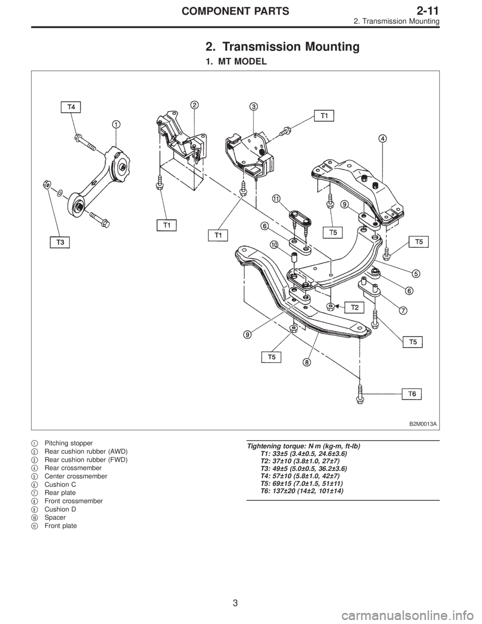
2. Transmission Mounting
1. MT MODEL
B2M0013A
�1Pitching stopper
�
2Rear cushion rubber (AWD)
�
3Rear cushion rubber (FWD)
�
4Rear crossmember
�
5Center crossmember
�
6Cushion C
�
7Rear plate
�
8Front crossmember
�
9Cushion D
�
10Spacer
�
11Front plate
Tightening torque: N⋅m (kg-m, ft-lb)
T1: 33±5 (3.4±0.5, 24.6±3.6)
T2: 37±10 (3.8±1.0, 27±7)
T3: 49±5 (5.0±0.5, 36.2±3.6)
T4: 57±10 (5.8±1.0, 42±7)
T5: 69±15 (7.0±1.5, 51±11)
T6: 137±20 (14±2, 101±14)
3
2-11COMPONENT PARTS
2. Transmission Mounting
Page 238 of 2248
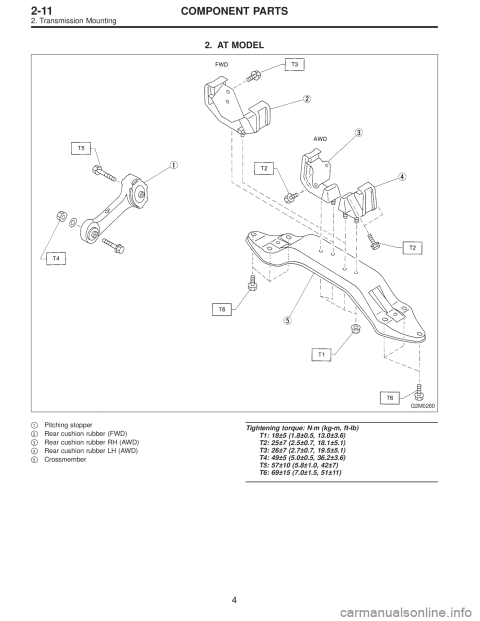
2. AT MODEL
G2M0260
�1Pitching stopper
�
2Rear cushion rubber (FWD)
�
3Rear cushion rubber RH (AWD)
�
4Rear cushion rubber LH (AWD)
�
5Crossmember
Tightening torque: N⋅m (kg-m, ft-lb)
T1: 18±5 (1.8±0.5, 13.0±3.6)
T2: 25±7 (2.5±0.7, 18.1±5.1)
T3: 26±7 (2.7±0.7, 19.5±5.1)
T4: 49±5 (5.0±0.5, 36.2±3.6)
T5: 57±10 (5.8±1.0, 42±7)
T6: 69±15 (7.0±1.5, 51±11)
4
2-11COMPONENT PARTS
2. Transmission Mounting
Page 240 of 2248

2. Engine
A: REMOVAL
1. Set the vehicle on lift arms.
2. Open front hood and support with a stay.
3. Release fuel pressure.
4. Disconnect battery cable and remove battery from vehicle.
5. Drain coolant.
6. Remove cooling system.
With A/C
7. Collect refrigerant, and remove pressure hoses.
8. Remove air intake system.
9. Remove canister and bracket.
10. Disconnect connectors, cables and hoses.
11. Remove power steering pump from bracket.
12. Remove front exhaust pipe and center exhaust pipe.
13. Remove nuts which hold lower side of transmission to
engine.
14. Remove nuts which install front cushion rubber onto front
crossmember.
AT model
15. Separate torque converter from drive plate.
16. Remove pitching stopper.
17. Disconnect fuel delivery hose, return hose and evaporation
hoses.
18. Support engine with a lifting device and wire ropes.
19. Support transmission with a garage jack.
20. Remove bolts which hold upper side of transmission to
engine.
21. Remove engine from vehicle.
�
�
�
�
�
�
�
�
�
�
�
�
�
�
�
6
2-11SERVICE PROCEDURE
2. Engine
Page 250 of 2248
G2M0294
15) Separate torque converter from drive plate. (AT model)
(1) Lower the vehicle.
(2) Remove service hole plug.
(3) Remove bolts which hold torque converter to drive
plate.
(4) Remove other bolts while rotating the engine using
ST.
ST 499977000 CRANK PULLEY WRENCH
G2M0295
16) Remove pitching stopper.
B2M0336
17) Disconnect fuel delivery hose, return hose and evapo-
ration hose.
CAUTION:
�Disconnect hose with its end wrapped with cloth to
prevent fuel from splashing.
�Catch fuel from hose into container.
G2M0297
18) Support engine with a lifting device and wire ropes.
G2M0298
19) Support transmission with a garage jack.
CAUTION:
Before moving engine away from transmission, check
to be sure no work has been overlooked. Doing this is
very important in order to facilitate re-installation and
because transmission lowers under its own weight.
16
2-11SERVICE PROCEDURE
2. Engine
Page 252 of 2248

B: INSTALLATION
1. Install engine to transmission.
2. Tighten bolts which hold upper side of transmission to engine.
3. Remove lifting device and wire rope.
4. Remove garage jack.
5. Install pitching stopper.
AT model
6. Install torque converter onto drive plate.
7. Install canister and bracket.
8. Install power steering pump on bracket.
9. Tighten nuts which hold lower side of transmission to engine.
10. Tighten nuts which install front cushion rubber onto cross-
member.
11. Install front exhaust pipe and center exhaust pipe.
12. Connect hoses, connectors and cables.
13. Install air intake system.
�Air intake duct
�Air cleaner element and upper cover.
With A/C
14. Install A/C pressure hoses.
15. Install cooling system.
16. Install battery onto the vehicle, and connect cables.
17. Fill coolant.
18. Check ATF level, and connect if necessary. [AT]
19. Correct power steering oil, and bleed air.
20. Remove front hood stay, and close front hood.
21. Take off the vehicle from lift arms.
�
�
�
�
�
�
�
�
�
�
�
�
18
2-11SERVICE PROCEDURE
2. Engine
 Separate torque converter from drive plate. (AT model)
(1) Lower the vehicle.
(2) Remove service hole plug.
(3) Remove bolts which hold torque converter to drive
plate.
(4) Remove other bo")