Page 1002 of 1701
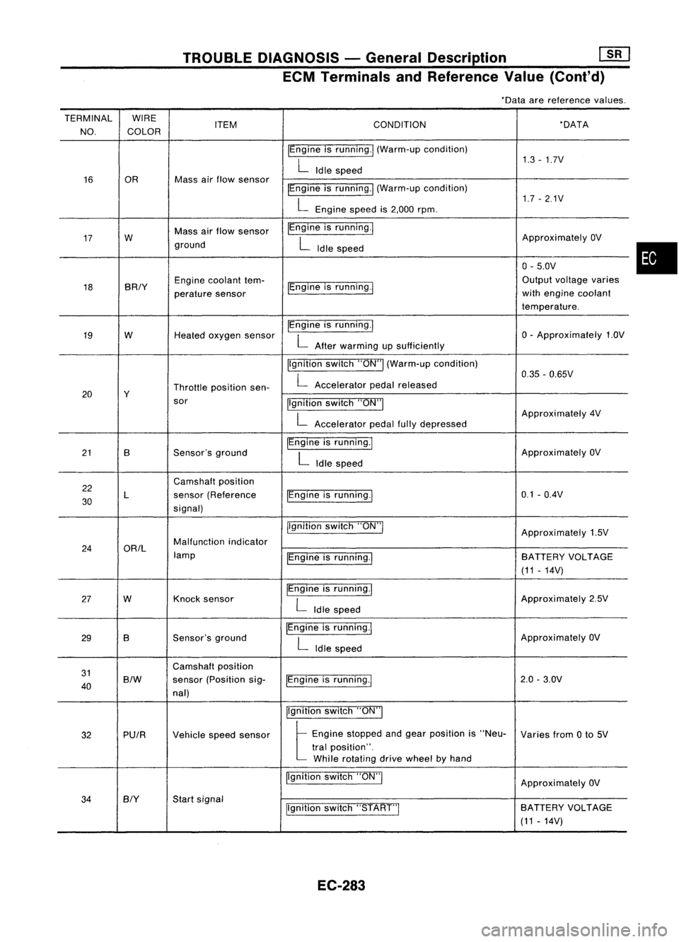
TROUBLEDIAGNOSIS -General Description
[ill
ECM Terminals andReference Value(Conl'd)
*Data arereference values.
TERMINAL WIRE
NO. COLOR ITEM
CONDITION *DATA
IEngine isrunning.1 (Warm-up condition)
1.3-1.7V
L
Idle speed
16 OR Mass
airflow sensor
IEngineisrunning.1 (Warm-up condition)
1.7-2.1V
L
Engine speedis2,000 rpm.
17 W Mass
airflow sensor IEngine
isrunning.!
ApproximatelyOV
ground
L
Idle speed
0-5.0V
18 BRIY Engine
coolant tem-
IEngineisrunning.! Output
voltage varies
perature sensor with
engine coolant
temperature.
19 W
Heatedoxygen sensor IEngine
isrunning.1
0-Approximately 1.OV
L
After warming upsufficiently
Ilgnition switch"ON"I(Warm-up condition)
0.35-0.65V
Throttle position sen-
L
Accelerator pedalreleased
20 Y
sor Ilgnitionswitch"ON"I
L
Approximately
4V
Accelerator pedalfullydepressed
21 B Sensor'sground IEngine
isrunning.1
ApproximatelyOV
L
Idle speed
22 Camshaft
position
30 L
sensor
(Reference IEngineisrunning.1 0.1
-O.4V
signal)
jlgnitionswitch"ON"!
Approximately1.5V
24 ORIL Malfunction
indicator
lamp IEngineisrunning.1 BATTERY
VOLTAGE
(11 -14V)
27 W Knock
sensor IEngine
isrunning.1
Approximately2.5V
L
Idle speed
29 B Sensor's
ground IEngine
isrunning.1
ApproximatelyOV
L
Idle speed
31 Camshaft
position
40
S/W
sensor
(Position sig-
IEngineisrunning.! 2.0
-3.0V
nal)
Ilgnitionswitch"ON"I
32 PUIR
Vehiclespeedsensor
t
Eng;ne "opped andge., po,;!;on ;,"Neo-
Variesfrom0to 5V
tral position".
While rotating drivewheel byhand
Ilgnition switch"ON"!
ApproximatelyOV
34
BIY
Start
signal
Ilgnitionswitch"START"I SA
TTERY VOLTAGE
(11 -14V)
EC-283
•
Page 1016 of 1701
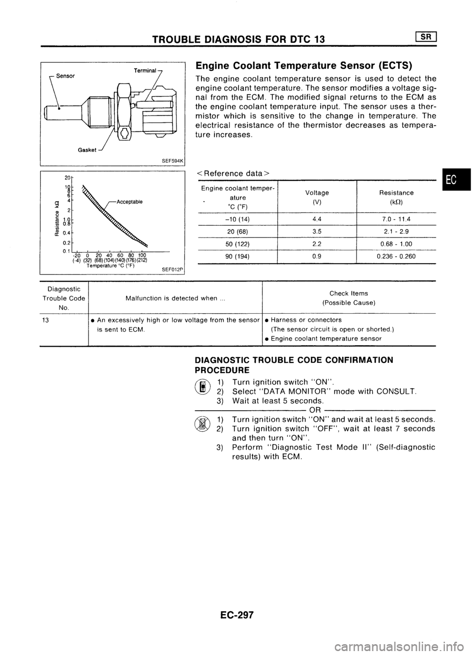
TROUBLEDIAGNOSIS FOROTC13
20
19
6
9
4
~ 2
~ 1.0
1ij
0.8
'w
8!
04
0.2
0.1
.20 020 40 6080100
(-4) (32) (68)(104)(140)(176)(212)
Temperature 'C
(OF)
SEF594K
SEF012P Engine
Coolant Temperature Sensor(ECTS)
The engine coolant temperature sensorisused todetect the
engine coolant temperature. Thesensor modifies avoltage sig-
nal from theECM. Themodified signalreturns tothe ECM as
the engine coolant temperature input.Thesensor usesather-
mistor whichissensitive tothe change intemperature. The
electrical resistance ofthe thermistor decreases astempera-
ture increases.
<
Reference data>
Engine coolant temper-
Voltage Resistance
ature
.
(V)(kQ)
'C ("F)
-10 (14) 4.4
7.0-11.4
20 (68) 3.5
2.1-2.9
50 (122) 2.20.68-1.00
90 (194) 0.9
0.236-0.260
•
Diagnostic
Trouble Code
No. Malfunction
isdetected when... Check
Items
(Possible Cause)
13 •
An excessively highorlow voltage fromthesensor •Harness orconnectors
is sent toECM. (Thesensor circuitisopen orshorted.)
• Engine coolant temperature sensor
DIAGNOSTIC TROUBLECODECONFIRMATION
PROCEDURE
rF.i\
1)Turn ignition switch"ON".
~ 2)Select "DATA MONITOR" modewithCONSULT.
3) Wait atleast 5seconds.
---------- OR----------
rm
1)Turn ignition switch"ON"andwait atleast 5seconds.
~ 2)Turn ignition switch"OFF", waitatleast 7seconds
and then turn"ON".
3) Perform "Diagnostic TestMode II"(Self-diagnostic
results) withECM.
EC-297
Page 1017 of 1701
TROUBLEDIAGNOSIS FORDTC13 ~
Engine Coolant Temperature Sensor(ECTS)
(Cont'd)
EC-ECTS-01
~ENGlNE COOLANT
TEMPERATURE
SENSOR
@lID
Il:j.JJ
4=U
BR/Y B
I I
BR/Y ~ B
$--1--$
BR/Y
U])
B _.
Detectable line
for DTC
-: Non-detectable
line forDTC
~~
@
L
~
~ GY
•
t
BR/Y
B
B
Ii1'sH
~
12-91
TW GND
GND
ECM
-A -A
(ECCS
CONTROL
MODULE)
em
em
L
EC-298 HEC005
Page 1018 of 1701
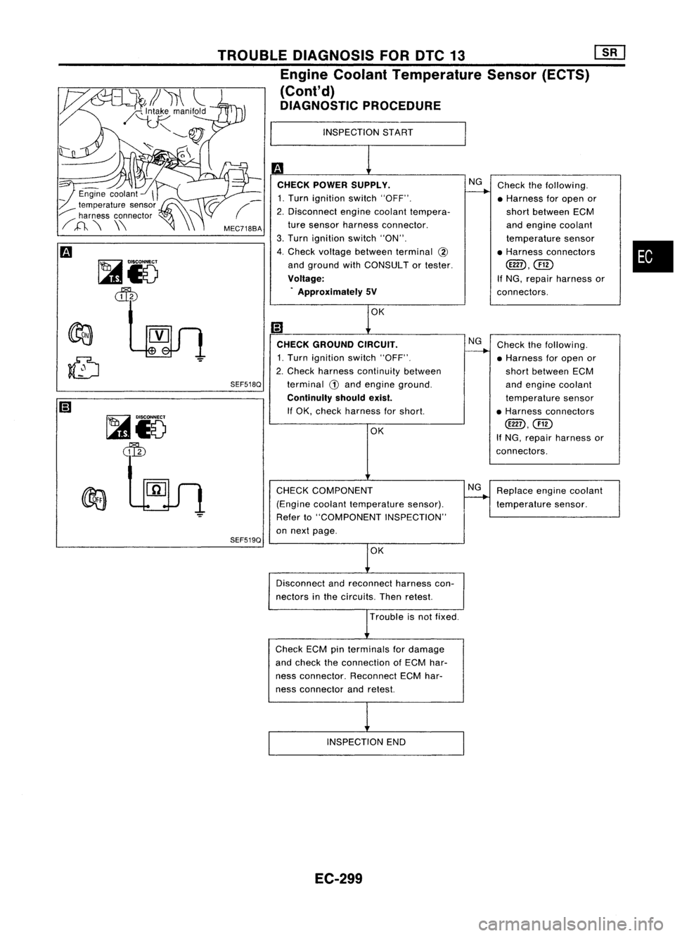
•
Check
thefollowing.
• Harness foropen or
short between ECM
and engine coolant
temperature sensor
• Harness connectors
@D,@)
If NG, repair harness or
connectors.
Replace enginecoolant
temperature sensor.
Check
thefollowing.
• Harness foropen or
short between ECM
and engine coolant
temperature sensor
• Harness connectors
@D.@)
If NG. repair harness or
connectors.
NG
NG
OK
CHECK COMPONENT
(Engine coolanttemperature sensor).
Refer to"COMPONENT INSPECTION"
on next page.
CHECK
GROUND CIRCUIT.
1. Turn ignition switch"OFF".
2. Check harness continuity between
terminal
CD
and engine ground.
Continuity shouldexist.
If OK, check harness forshort.
INSPECTION
START
OK
m
CHECK POWER SUPPLY.
1. Turn ignition switch"OFF".
2. Disconnect enginecoolant tempera-
ture sensor harness connector.
3. Turn ignition switch"ON".
4. Check voltage between terminal
@
and ground withCONSULT ortester.
Voltage: . Approximately 5V
SEF518Q
SEF519Q
MEC7188A
TROUBLE
DIAGNOSIS FORDTC13
mJ
Engine Coolant Temperature Sensor(ECTS)
(Cont'd)
DIAGNOSTIC PROCEDURE
~i5
~
~io
~
Disconnectandreconnect harnesscon-
nectors inthe circuits. Thenretest.
Trouble isnot fixed.
Check ECMpinterminals fordamage
and check theconnection ofECM har-
ness connector. ReconnectECMhar-
ness connector andretest.
INSPECTION END
EC-299
Page 1019 of 1701
TROUBLEDIAGNOSIS FORDTC13 ~
Engine Coolant Temperature Sensor(ECTS)
(Cont'd)
COMPONENT INSPECTION
SEF152P Engine
coolant temperature sensor
Check resistance asshown inthe figure.
Temperature °C
(OF)
20 (68)
50 (122)
90 (194)
Resistance
kQ
2.1 -2.9
0.68 -1.00
0.236 -0.260
If NG, replace enginecoolant temperature sensor.
EC-300
Page 1038 of 1701
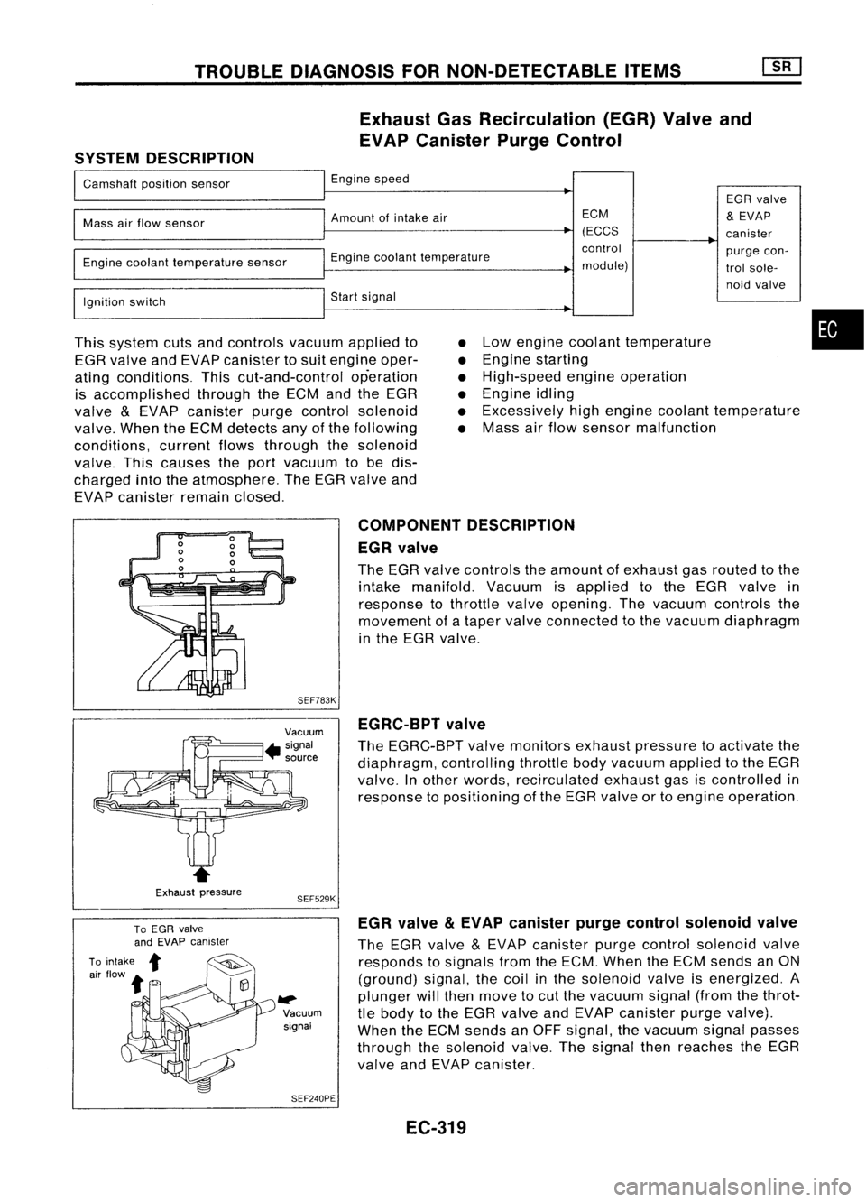
TROUBLEDIAGNOSIS FORNON-DETECTABLE ITEMS
Exhaust GasRecirculation (EGR)Valveand
EVAP Canister PurgeControl
SYSTEM DESCRIPTION
I
Camshaft positionsensor
I
Engine speed
EGRvalve
I
Mass
airflow sensor
I
Amount ofintake air ECM
&
EVAP
(ECCS canister
I
~Engine
coolanttemperature control
purgecon-
Engine coolant temperature sensor
module)trolsole-
I
noid
valve
Ignition switch
I
Start signal
I
This system cutsandcontrols vacuumappliedto
EGR valve andEVAP canister tosuit engine oper-
ating conditions. Thiscut-and-control operation
is accomplished throughtheECM andtheEGR
valve
&
EVAP canister purgecontrol solenoid
valve. WhentheECM detects anyofthe following
conditions, currentflowsthrough thesolenoid
valve. Thiscauses theport vacuum tobe dis-
charged intotheatmosphere. TheEGR valve and
EVAP canister remainclosed.
•
•
•
•
•
•
Low
engine coolant temperature
Engine starting
High-speed engineoperation
Engine idling
Excessively highengine coolant temperature
Mass airflow sensor malfunction
•
Exhaust pressure COMPONENT
DESCRIPTION
EGR valve
The EGR valve controls theamount ofexhaust gasrouted tothe
intake manifold. Vacuumisapplied tothe EGR valve in
response tothrottle valveopening. Thevacuum controls the
movement ofataper valve connected tothe vacuum diaphragm
in the EGR valve.
SEF783K EGRC-BPT valve
The EGRC-BPT valvemonitors exhaustpressure toactivate the
diaphragm, controllingthrottlebodyvacuum appliedtothe EGR
valve. Inother words, recirculated exhaustgasiscontrolled in
response topositioning ofthe EGR valve ortoengine operation.
SEF529K
~ Vacuumsignal
SEF240PE EGR
valve
&
EVAP canister purgecontrol solenoid valve
The EGR valve
&
EVAP canister purgecontrol solenoid valve
responds tosignals fromtheECM. When theECM sends anON
(ground) signal,thecoil inthe solenoid valveisenergized. A
plunger willthen move tocut the vacuum signal(fromthethrot-
tle body tothe EGR valve andEVAP canister purgevalve).
When theECM sends anOFF signal, thevacuum signalpasses
through thesolenoid valve.Thesignal thenreaches theEGR
valve andEVAP canister.
EC-319
Page 1054 of 1701
TROUBLEDIAGNOSIS FORNON-DETECTABLE ITEMS
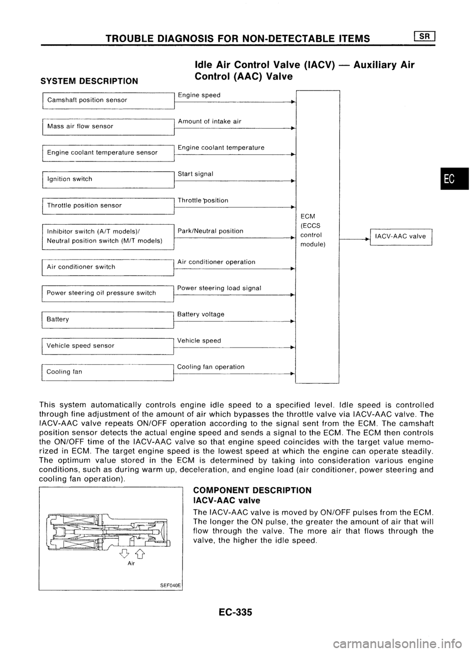
SYSTEM DESCRIPTION Idle
AirControl Valve(IACV) -Auxiliary Air
Control (AAC)Valve
Camshaft positionsensor Engine
speed
~
I
Amount ofintake air
Mass airflow sensor
I
Engine coolant temperature sensor Engine
coolant temperature
I
Ignition switch Start
signal
I
Throttle position sensor Throttle
"position
I
ECM
Inhibitor switch(A/Tmodels)/ Park/Neutral
position (ECCS
control
!
IACV-AAC valve
I
Neutral position switch(M/Tmodels)
module)
Air conditioner switch Air
conditioner operation
Power steering oilpressure switch Power
steering loadsignal
I
Battery Battery
voltage
Vehicle speedsensor Vehicle
speed
I
l
Cooling fan Cooling
fanoperation
I
This system automatically controlsengineidlespeed toaspecified level.Idlespeed iscontrolled
through fineadjustment ofthe amount ofair which bypasses thethrottle valveviaIACV-AAC valve.The
IACV-AAC valverepeats ON/OFF operation according tothe signal sentfrom theECM. Thecamshaft
position sensordetects theactual engine speedandsends asignal tothe ECM. TheECM thencontrols
the ON/OFF timeofthe IACV-AAC valvesothat engine speedcoincides withthetarget valuememo-
rized inECM. Thetarget engine speedisthe lowest speedatwhich theengine canoperate steadily.
The optimum valuestored inthe ECM isdetermined bytaking intoconsideration variousengine
conditions, suchasduring warmup,deceleration, andengine load(airconditioner, powersteering and
cooling fanoperation).
COMPONENTDESCRIPTION
IACV-AAC valve
The IACV-AAC valveismoved byON/OFF pulsesfromtheECM.
The longer theONpulse, thegreater theamount ofair that will
flow through thevalve. Themore airthat flows through the
valve, thehigher theidle speed.
Air SEF040E
EC-335
•
Page 1062 of 1701
TROUBLEDIAGNOSIS FORNON-DETECTABLE ITEMS
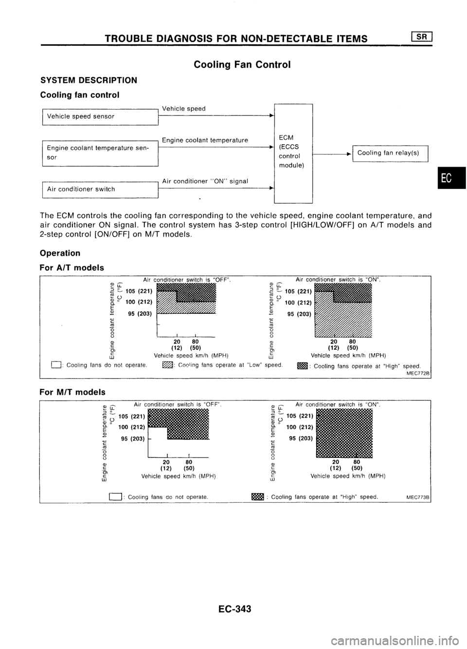
Cooling FanControl
SYSTEM DESCRIPTION
Cooling fancontrol
I
Vehicle speedsensor
I
Vehicle speed
Engine coolant temperature EGM
Engine coolant temperature sen- (EGGS
~
sor control
module)
I
Air conditioner switch
I
Air conditio~er "ON"signal
I
Goaling fanrelay(s)
•
The ECM controls thecooling fancorresponding tothe vehicle speed,engine coolant temperature, and
air conditioner ONsignal. Thecontrol system has3-step control [HIGH/LOW/OFF] onA/T models and
2-step control [ON/OFF] onM/T models.
Operation
For AIT models
Airconditioner switchis"ON".
20 80
(12) (50)
Vehicle speedkm/h(MPH)
m!lll:
Cooling fansoperate at"High" speed.
MEC772B
~u:
~ ?-
105 (221)
~ 0
2i
0
100 (212)
E
2
95(203)
C
'"
o
o
o
20 80
OJ
(12) (50) .~
Vehicle speedkm/h(MPH) ~
~: Cooling fansoperate at"Low" speed.
~LL
.3
?-
105 (221)
~o
2i
0
100 (212)
E
2
95(203)
C
'"
o
o
o
OJ
c:
.0,
c
w
0:
Cooling fansdonot operate.
For MIT models
Airconditioner switchis"OFF".
2080
(12) (50)
Vehicle speedkm/h(MPH)
~
u:
Airconditioner switchis"ON".
::J
0
1il
Z;
105 (221)
OJ
0
E
100(212)
OJ
- 95(203)
C
'"
o
o
o
OJ
c
0,
c
ill
I
20 80
(12) (50)
Vehicle speedkm/h(MPH)
~u:
::J
0
1il ;-
105 (221)
OJ
0
~ 100(212)
<1>
- 95(203)
C
'"
o
o
o
OJ
c
.0,
c
ill
0:
COOling fansdonot operate. m
:Cooling fansoperate at"High" speed.
MEC773B
EC-343