Page 721 of 1701

CONSULT Reference ValueinData Monitor
Mode 74
Major Sensor Reference GraphinData
Monitor Mode 76
ECM Terminals andReference Value 78
TROUBLE DIAGNOSIS FORPOWER SUPPLY 88
Main")
CONTENTS(Cont'd.)
CONSULT Reference ValueinData Monitor
Mode 74
Major Sensor Reference GraphinData
Monitor Mode 76
ECM Terminals andReference Value 78
TROUBLE DIAGNOSIS FORPOWER SUPPLY 88
Main Power Supply andGround Circuit.. 88
TROUBLE DIAGNOSIS FORDTC11 94
Camshaft PositionSensor(CMPS) 94
TROUBLE DIAGNOSIS FORDTC
12 101
Mass AirFlow Sensor (MAFS) 101
TROUBLE DIAGNOSIS FORDTC
13 108
Engine Coolant Temperature Sensor(ECTS) 108
TROUBLE DIAGNOSIS FORDTC
21 113
Ignition Signal 113
TROUBLE DIAGNOSIS FORDTC
34 119
Knock Sensor (KS) 119
TROUBLE DIAGNOSIS FORDTC
41 124
Intake AirTemperature Sensor(IATS) 124
TROUBLE DIAGNOSIS FORNON-DETECTABLE
ITEMS , '"
.128
Throttle Position Sensor 128
Vehicle SpeedSensor (VSS) 133
Start Signal 138
Injector 141
Fuel Pump 145
Idle AirControl Valve(IACV) -Auxiliary Air
Control (AAC)Valve 150
Cooling FanControl 156
Power Steering OilPressure Switch 169
Park/Neutral PositionSwitch 173
EVAP Canister PurgeControl Solenoid Valve179
EGR Valve andEVAP Canister PurgeControl
Solenoid Valve 183
Heated Oxygen Sensor(H02S) 189
Oxygen Sensor(02S) 194
Valve Timing Control (VTC) 198
IACV-FICD SolenoidValve 204
Electrical LoadSignal 211
Torque Converter ClutchSolenoid Valve 219
MIL
&
Data LinkConnectors 223
SR
ENGINE ANDEMISSION CONTROL OVERALL
SYSTE M
226
Circuit Diagram 226
System Diagram 227
ECCS Component PartsLocation 228
Vacuum HoseDrawing 231
System Chart... 232
ENGINE
ANDEMISSION BASICCONTROL
SYSTEM DESCRiPTION
233
Multipart FuelInjection (MFI)System 233
Distributor Ignition
(01)
System 235
Air Conditioning CutControl 236
Fuel CutControl (atnoload
&
high engine
speed) 237
EVAPORATIVE EMISSIONSYSTEM
238
Description 238
Inspection 238
POSITIVE CRANKCASE VENTILATION
240
Description 240
Inspection 240
BASIC SERVICE
PROCEDURE 241
Fuel Pressure Release 241
Fuel Pressure Check 241
Fuel Pressure Regulator Check 242
Injector Removal andInstallation 242
Idle Speed/Ignition Timing/IdleMixtureRatio
Adjustment 243
ON-BOARD DIAGNOSTIC SYSTEMDESCRIPTION ..250
Malfunction IndicatorLamp(MIL) 250
CONSULT 254
TROUBLE DIAGNOSIS -General Description
264
Introduction 264
Work Flow 265
Description forWork Flow 266
Diagnostic Worksheet 267
Diagnostic TroubleCode(DTC) Chart 268
Fail-Safe Chart 270
Basic Inspection 271
Symptom MatrixChart. 274
CONSULT Reference ValueinData Monitor
Mode 277
Major Sensor Reference GraphinData
Monitor Mode 279
ECM"Terminals andReference Value 281
TROUBLE DIAGNOSIS FORPOWER SUPPLY
286
Main Power Supply andGround Circuit.. 286
TROUBLE DIAGNOSIS FORDTC
11 289
Camshaft PositionSensor(CMPS) 289
TROUBLE DIAGNOSIS FORDTC
12 293
Mass AirFlow Sensor (MAFS) 293
TROUBLE DIAGNOSIS FORDTC
13 297
Engine Coolant Temperature Sensor(ECTS) 297
TROUBLE DIAGNOSIS FORDTC
21 301
Ignition Signal 301
TROUBLE DIAGNOSIS FORDTC
34 306
Knock Sensor (KS) 306
Page 736 of 1701
ENGINEANDEMISSION CONTROLOVERALLSYSTEM
ECCS Component PartsLocation -GA14DE,
GA 16DE forEurope andIsrael
Mass airflow sensor
Throttle positionsensor
Power steering oil
pressure switch
Engine coolant temperature
sensor
IACV-FICDsolenoidvalve
IACV-AAC valveFast
idlecam EGRvalve
&
EVAP canister purgecontrol solenoid valve
Distributor withbuilt-in camshaft position
sensor, powertransistor andignition coil
•
Throttle positionsensor
SEF122R
EC-17
Page 737 of 1701
ENGINEANDEMISSION CONTROL OVERALLSYSTEM
ECCS Component PartsLocation -GA15DE
Distributor withbuilt-in camshaft position
sensor, powertransistor andignition coil
EGR
valve
&
EVAP canister purgecontrol solenoid valve
(Only M/Tmodels)
f
EGR valve (Only M/Tmodels)
Fuel filter
EVAPcanister
Oxygen sensor
Mass
airflow sensor
IACV-AAC valve
(with FICD
solenoid valve)
Throttle
position sensor
Engine coolant temperature
sensor
Massairflow sensor
Throttleposition sensor
SEF123R
EC-18
Page 738 of 1701
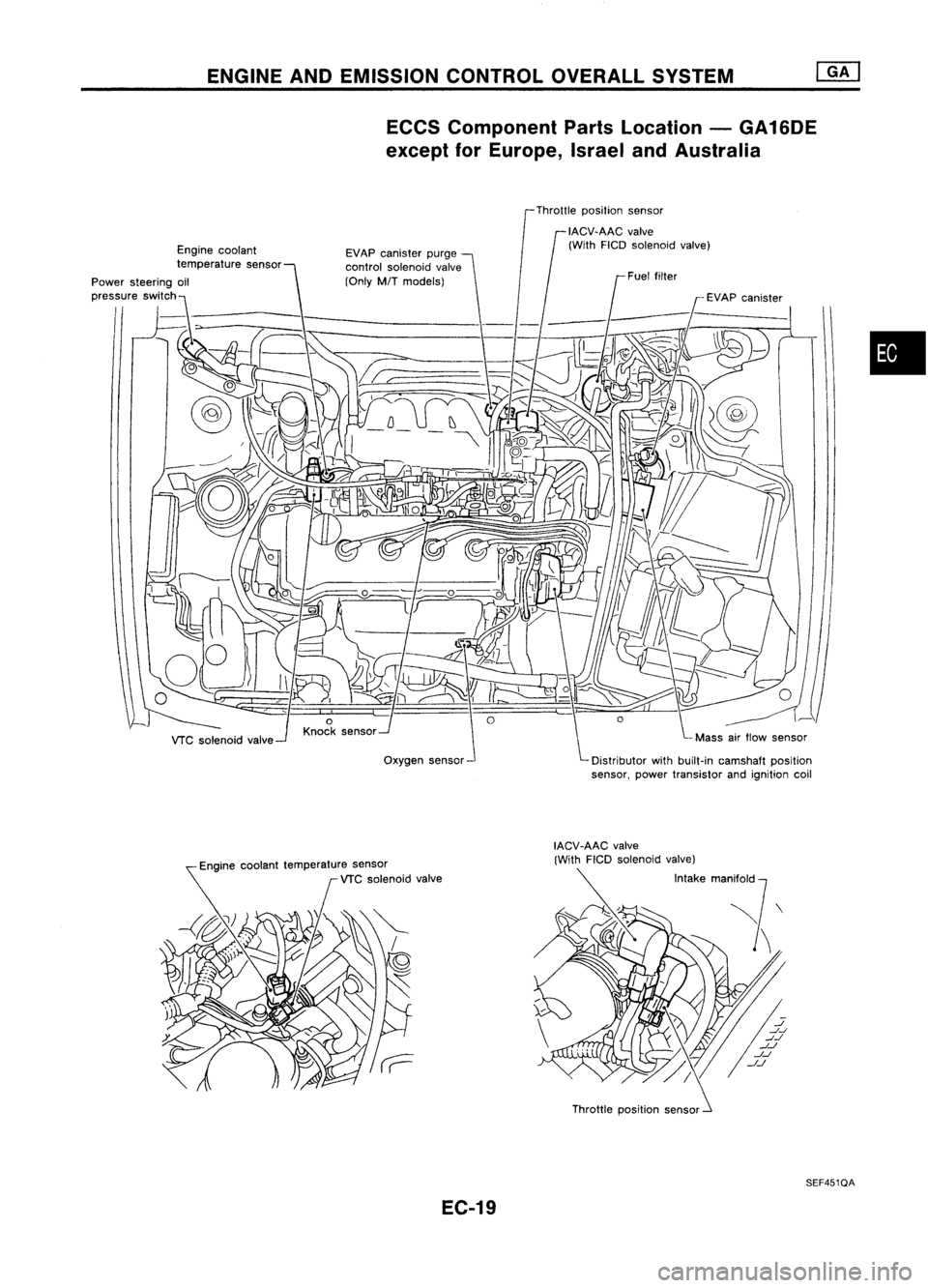
ENGINEANDEMISSION CONTROLOVERALLSYSTEM
ECCS Component PartsLocation -GA16DE
except forEurope, IsraelandAustralia
Throttle position sensor
Engine coolant
temperature sensor
Power steering oil
,,,,,"to
'WI"h~~>- __
"7-_
VTC solenoid valve EVAP
canister purge
control solenoid valve
(Only M/Tmodels)
Oxygen sensor
•
Engine coolant temperature sensor
VTC solenoid valve
EC-19 Throttle
position sensor
SEF451QA
Page 739 of 1701
ENGINEANDEMISSION CONTROL OVERALLSYSTEM
ECCS Component PartsLocation -GA16DE for
Australia
Heated oxygen sensor
(AfT
models)
Oxygen sensor
(MfT
models)
Engine
coolant temperature
sensor
VTCsolenoid valve EGR
valve
&
EVAP
canister purge
control solenoid valve Throttle
position sensor
IACV-AAC valve(withFICO solenoid valve)
Distributor withbuilt-in camshaft position
sensor, powertransistor andignition coil
Engine coolant temperature sensor
VTC solenoid valve
Throttlepositionsensor
SEF124R
EC-20
Page 742 of 1701

ENGINEANDEMISSION BASICCONTROL SYSTEMDESCRIPTION
System Chart
I
Camshaft positionsensor
'1
Fuel
injection
&
mixture
ratio control Injectors
Knock sensor
Distributorignitionsystem Powertransistor
Mass airflow sensor
Engine coolant temperature
sensor
Ignition switch Idle
aircontrol system
Fuel pump control
*4
IACV-AAC valve(WithFICD
solenoid valve)
Fuel pump relay
•
'5
Throttle
positionsensor
Neutral positionllnhibitor
switch
Air conditioner switch ECM
(ECCS
control
module)
2
Oxygen sensormonitor
&
On-board diagnostic system
5
Torque converter clutchcan-
cel solenoid valvecontrol
(A/T models) Malfunction
indicatorlamp
(On theinstrument panel)
Torque converter clutchsole-
noid valve
VTC solenoid valve
*6
Air
conditioner relays
Cooling
fanrelay
EVAP canister purgecontrol
solenoid valve
Cooling
fancontrol
Air conditioner cutcontrol
during acceleration
Valve timing control
EVAP canister purgecontrol
7
6
Power
steering oilpressure
switch Battery
voltage
Intake airtemperature sensor
*3
I
Vehicle speedsensor
*2
I
Oxygen sensor
8
'8
Electrical load
• Rear defogger switch
• Lighting switch EGR
&
EVAP canister purge
control EGR
valve
&
EVAP canister
purge control solenoid valve
*1: Except forEurope andIsrael
*2: Heated oxygen sensor(ForEurope andIsrael, andAustralia A/Tmodels)
Oxygen sensor(Except forEurope andIsrael, andAustralia A/Tmodels)
*3: For Australia
*4: IACV-AAC valveandIACV-FICD solenoidvalve(ForEurope andIsrael)
IACV-AAC valve(withFICDsolenoid valve)(Except forEurope andIsrael)
'5: Except forEurope
*6: GA16DE exceptforEurope andIsrael
*7: GA16DE MITmodels exceptforEurope, IsraelandAustralia
*8: For Europe andIsrael andAustralia, andGA15DE MITmodels
EC-23
Page 743 of 1701
System
INPUT/OUTPUT SIGNALLINE
Camshaft positionsensor
Mass airflow sensor
Engine coolant temperature sensor
*1
Oxygen")
ENGINEANDEMISSION BASICCONTROL SYSTEMDESCRIPTION
Multipart FuelInjection (MFI)System
INPUT/OUTPUT SIGNALLINE
Camshaft positionsensor
Mass airflow sensor
Engine coolant temperature sensor
*1
Oxygen sensor
Throttle position sensor
Neutral position/Inhibitor switch
Vehicle speedsensor
~gnition switch
Air conditioner switch
Power steering oilpressure switch
Battery Engine
speedandpiston position
Amount ofintake air
Engine coolant temperature
Density ofoxygen inexhaust gas
Throttle position
Throttle valveidleposition
Gear position
Vehicle speed
Start signal
Air conditioner operation
Power steering loadsignal
Battery voltage ECM
(ECCS
control module) Injector
*1: Heated oxygen sensor(ForEurope andIsrael, andAustralia A/Tmodels)
Oxygen sensor(Except forEurope andIsrael, andAustralia A/Tmodels)
BASIC MULTIPORT FUELINJECTION
SYSTEM
The amount offuel injected fromthefuel injector
is determined bythe ECM. TheECM controls the
length oftime thevalve remains open(injection
pulse duration). Theamount offuel injected isa
program valueinthe ECM memory. Theprogram
value ispreset byengine operating conditions.
These conditions aredetermined byinput signals
(for engine speedandintake air)from boththe
camshaft positionsensorandthemass airflow
sensor.
VARIOUS
FUELINJECTION
INCREASE/DECREASE COMPENSATION
In addition, theamount offuel injected iscom-
pensated toimprove engineperformance under
various operating conditions aslisted below.
<
Fuel increase>
• During warm-up
• When starting theengine
• During acceleration
• Hot-engine operation
• When selector leverischanged from"N"to
"D"
(AfT
models only)
• High-load, high-speed operation
<
Fuel decrease>
• During deceleration
EC-24
Page 744 of 1701

•
OPEN
LOOPCONTROL
The open loopsystem condition referstowhen theECM detects
any ofthe following conditions. Feedbackcontrolstopsinorder
to maintain stabilized fuelcombustion.
• Deceleration andacceleration
• High-load, high-speed operation
• Engine idling
• Malfunction ofoxygen sensor*1 orits circuit
• Insufficient activationofoxygen sensor*1 atlow engine
coolant temperature
• High-engine coolanttemperature
• After shifting from"N"to"D"
• During warm-up
• When starting theengine
ENGINE
ANDEMISSION BASICCONTROL SYSTEMDESCRIPTION
[ill
Multipart FuelInjection (MFI)System (Cant'd)
MIXTURE RATIOFEEDBACK CONTROL(CLOSEDLOOP
CONTROL)
The mixture ratiofeedback systemprovides thebest air-fuel
mixture ratiofordriveability andemission control.Thethree
way catalyst canthen better reduce CO,HCand NOx emissions.
This system usesanoxygen sensor*1 inthe exhaust manifold
to monitor ifthe engine operation isrich orlean. TheECM
adjusts theinjection pulsewidthaccording tothe sensor volt-
age signal. Thismaintains themixture ratiowithin therange of
stoichiometric (idealair-fuel mixture).
MEF025DC
Thisstage isreferred toas the closed loopcontrol condition .
Feedback
signal
CLOSED
LOOP
CONTROL
MIXTURERATIOSELF-LEARNING CONTROL
The mixture ratiofeedback controlsystem monitors themixture
ratio signal transmitted fromtheoxygen sensor*1. Thisfeed-
back signal isthen senttothe ECM. TheECM controls thebasic
mixture ratioasclose tothe theoretical mixtureratioaspossi-
ble. However, thebasic mixture ratioisnot necessarily con-
trolled asoriginally designed. Bothmanufacturing differences
(i.e., mass airflow sensor hotfilm) andcharacteristic changes
during operation (i.e.,injector clogging) directlyaffectmixture
ratio.
Accordingly, thedifference betweenthebasic andtheoretical
mixture ratiosismonitored inthis system. Thisisthen com-
puted interms of"injection pulseduration" toautomatically
compensate forthe difference betweenthetwo ratios.
* 1: Heated oxygen sensor(ForEurope andIsrael, andAustra-
lia AIT models)
Oxygen sensor(Except forEurope andIsrael, andAustralia
AIT
models)
EC-25


Oxygen sensor
(MfT
models)
Engine
coolant temperature
sensor
VTCsolenoi")