Page 1068 of 1701
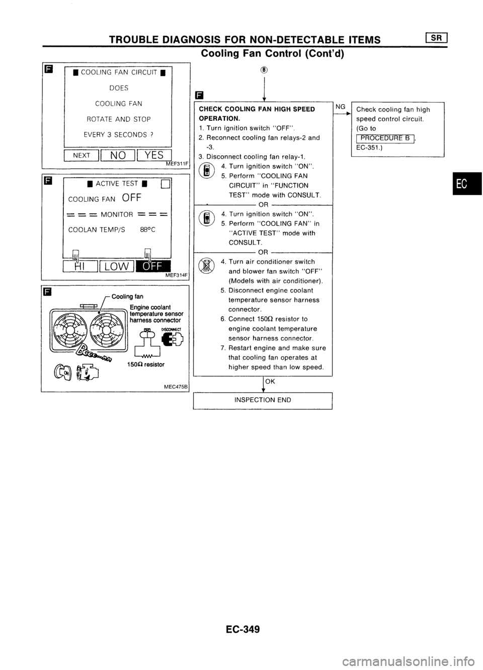
TROUBLEDIAGNOSIS FORNON-DETECTABLE ITEMS
Cooling FanControl (Cont'd)
• COOLING FANCIRCUIT.
DOES
Cooling fan
MEC475B
COOLING
FAN
•
Check
cooling fanhigh
speed control circuit.
(Go to
I
PROCEDURE B
I.
EC-351.)
NG
OK
CHECK
COOLING FANHIGH SPEED
OPERATION.
1. Turn ignition switch"OFF".
2. Reconnect coolingfanrelays-2 and
-3.
3. Disconnect coolingfanrelay-1.
(ij\
4.Turn ignition switch"ON".
~ 5.Perform "COOLING FAN
CIRCUIT" in"FUNCTION
TEST" modewithCONSULT.
OR
fiii\
4.Turn ignition switch"ON".
~ 5.Perform "COOLING FAN"in
"ACTIVE TEST"modewith
CONSULT.
OR
4. Turn airconditioner switch
and blower fanswitch "OFF"
(Models withairconditioner).
5. Disconnect enginecoolant
temperature sensorharness
connector.
6. Connect 150Qresistor to
engine coolant temperature
sensor harness connector.
7. Restart engineandmake sure
that cooling fanoperates at
higher speedthanlowspeed.
Ii
--- ---
150(1 resistor
ROTATE
ANDSTOP
EVERY 3SECONDS
"I
NEXT
II
NO
II
YES
I
MEF311F
COOLAN TEMP/S
•
ACTIVE TEST. D
COOLING FAN
OFF
= ==
MONITOR
clTJI
LOW
1.1-
MEF314F
Ii
Ii
INSPECTIONEND
EC-349
Page 1087 of 1701
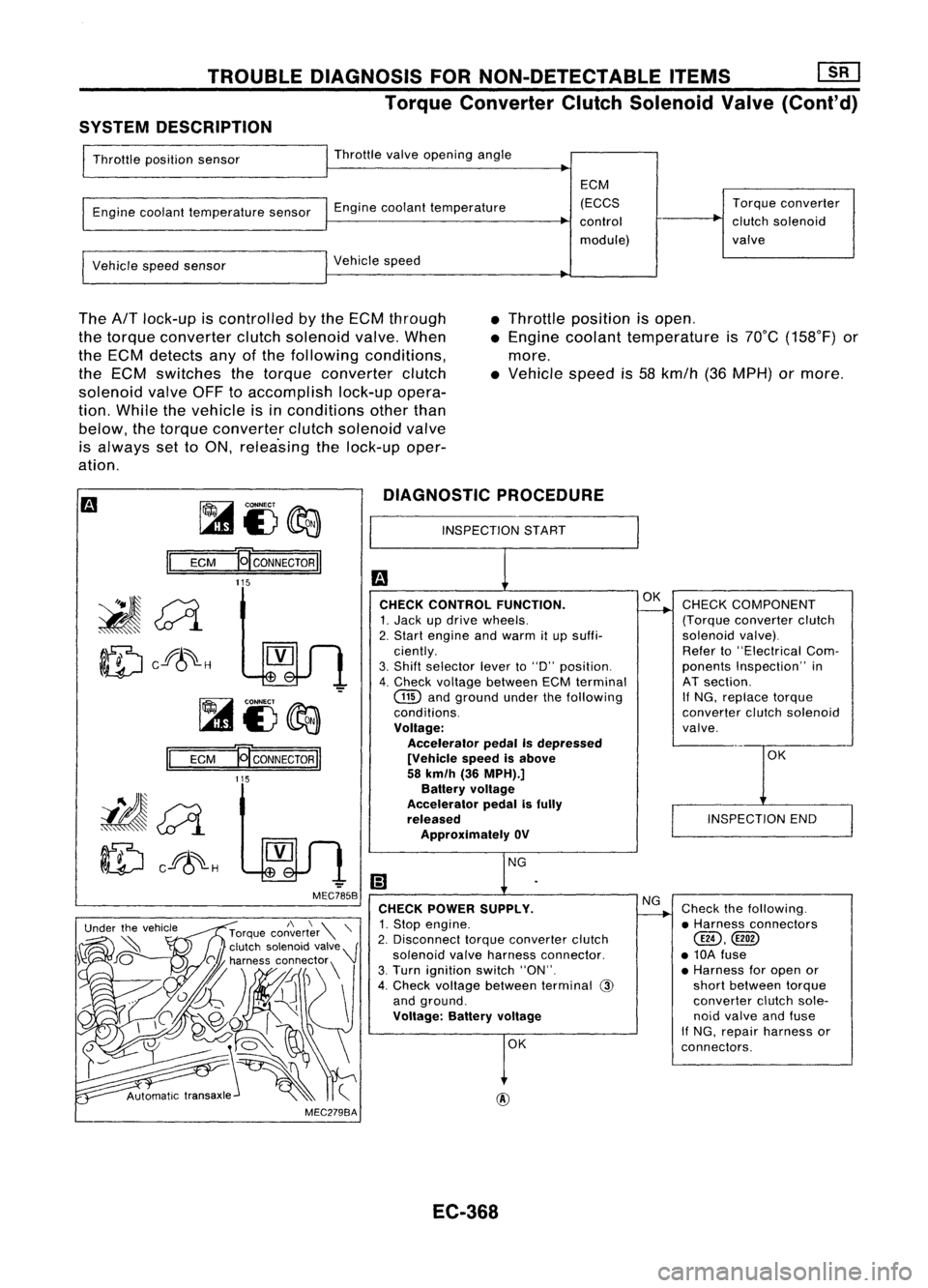
TROUBLEDIAGNOSIS FORNON-DETECTABLE ITEMS~
Torque Converter ClutchSolenoid Valve(Cont'd)
SYSTEM DESCRIPTION
Throttle position sensor Throttle
valveopening angle
Engine coolant temperature sensorEnginecoolant temperature ECM
(ECCS
control
module) Torque
converter
clutch solenoid
valve
Vehicle speedsensor Vehicle
speed
The
AfT
lock-up iscontrolled bythe ECM through
the torque converter clutchsolenoid valve.When
the ECM detects anyofthe following conditions,
the ECM switches thetorque converter clutch
solenoid valveOFFtoaccomplish lock-upopera-
tion. While thevehicle isinconditions otherthan
below, thetorque converter clutchsolenoid valve
is always settoON, relea'sing thelock-up oper-
ation. •
Throttle position isopen .
• Engine coolant temperature is70°C (158°F) or
more .
• Vehicle speedis58 kmfh (36MPH) ormore.
~i3~
II
ECM
E[CONNECTORII
DIAGNOSTIC
PROCEDURE
INSPECTION START
115
OK
INSPECTION END
CHECK
COMPONENT
(Torque converter clutch
solenoid valve).
Refer to"Electrical Com-
ponents Inspection" in
AT section.
If
NG, replace torque
converter clutchsolenoid
valve.
Check thefollowing.
• Harness connectors
@,
• 10A fuse
• Harness foropen or
short between torque
converter clutchsole-
noid valve andfuse
If NG, repair harness or
connectors.
NG
OK
OK
@
CHECK
CONTROL FUNCTION.
1. Jack updrive wheels.
2. Start engine andwarm itup suffi-
ciently.
3. Shift selector leverto"0" position.
4. Check voltage between ECMterminal
GID
andground underthefollowing
conditions.
Voltage: Accelerator pedalIsdepressed
[Vehicle speedisabove
58 km/h (36MPH).]
Battery voltage
Accelerator pedalisfully
released
Approximately OV
CHECK POWER SUPPLY.
1. Stop engine.
2. Disconnect torqueconverter clutch
solenoid valveharness connector.
3. Turn ignition switch"ON".
4. Check voltage between terminal
@
and ground.
Voltage: Batteryvoltage
-
MEC785B
MEC279BA
Ef
CONNECTOR
II
115
II
ECM
~~
ID
cf8~-H
EC-368
Page 1094 of 1701
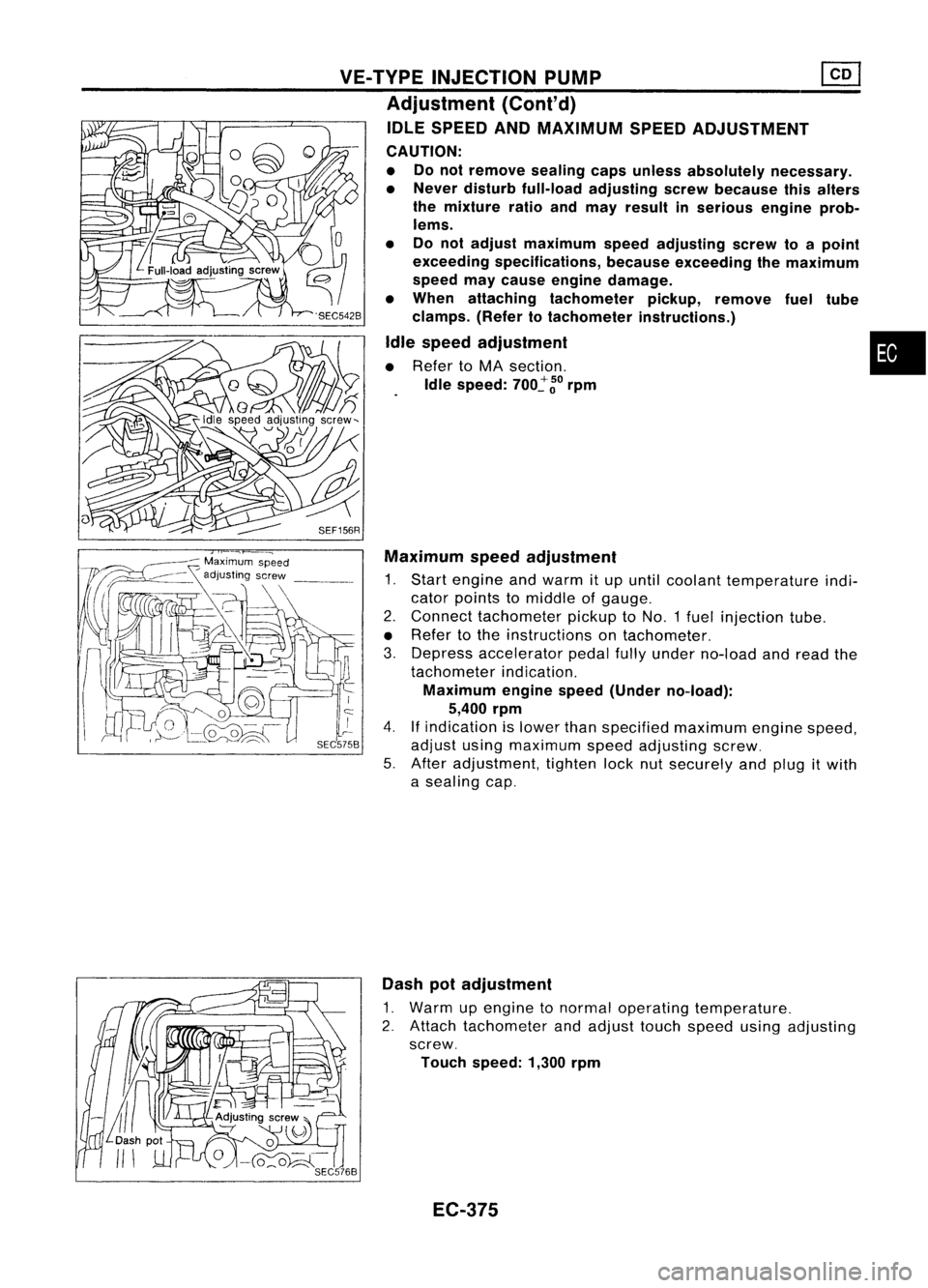
VE-TVPEINJECTION PUMP ~
Adjustment (Cont'd)
IDLE SPEED ANDMAXIMUM SPEEDADJUSTMENT
CAUTION:
• Donot remove sealingcapsunless absolutely necessary.
• Never disturb full-load adjusting screwbecause thisalters
the mixture ratioandmay result inserious engineprob-
lems.
• Donot adjust maximum speedadjusting screwtoapoint
exceeding specifications, becauseexceeding themaximum
speed maycause engine damage.
• When attaching tachometer pickup,remove fueltUbe
clamps. (Refertotachometer instructions.)
Idle speed adjustment •
• Refer toMA section.
Idle speed:
700~
~o
rpm
SEF156R Maximum speedadjustment
1. Start engine andwarm itup until coolant temperature indi-
cator points tomiddle ofgauge.
2. Connect tachometer pickuptoNO.1 fuelinjection tube.
• Refer tothe instructions ontachometer.
3. Depress accelerator pedalfullyunder no-load andread the
tachometer indication.
Maximum enginespeed(Under no-load):
5,400 rpm
4.
If
indication islower thanspecified maximum enginespeed,
adjust usingmaximum speedadjusting screw.
5. After adjustment, tightenlocknutsecurely andplug itwith
a sealing cap.
Dash potadjustment
1. Warm upengine tonormal operating temperature.
2. Attach tachometer andadjust touchspeed usingadjusting
screw.
Touch speed: 1,300rpm
EC-375
Page 1102 of 1701
relay-2ENGINE
ANDEMISSION CONTROLOVERALLSYSTEM
Component PartsLocation
Engine coolant
temperature sensor
Glowplugs
•
EC-383 SEF159R
Page 1105 of 1701
ENGINEANDEMISSION CONTROL OVERALLSYSTEM
System Chart
Ignition key
Engine coolant temperature
sensor Quick-glow
system
Partial loadadvance (PLA)
control Glow
relay
&
glow lamp
Solenoid timer
Engine speedsensor
Air conditioner switch
Battery voltage
Vehicle speedsensor
ECM
(Engine
control module) Coolingfancontrol
Air conditioner cutcontrol
EC-386
Cooling
fanrelay
Air conditioner relays
Page 1107 of 1701
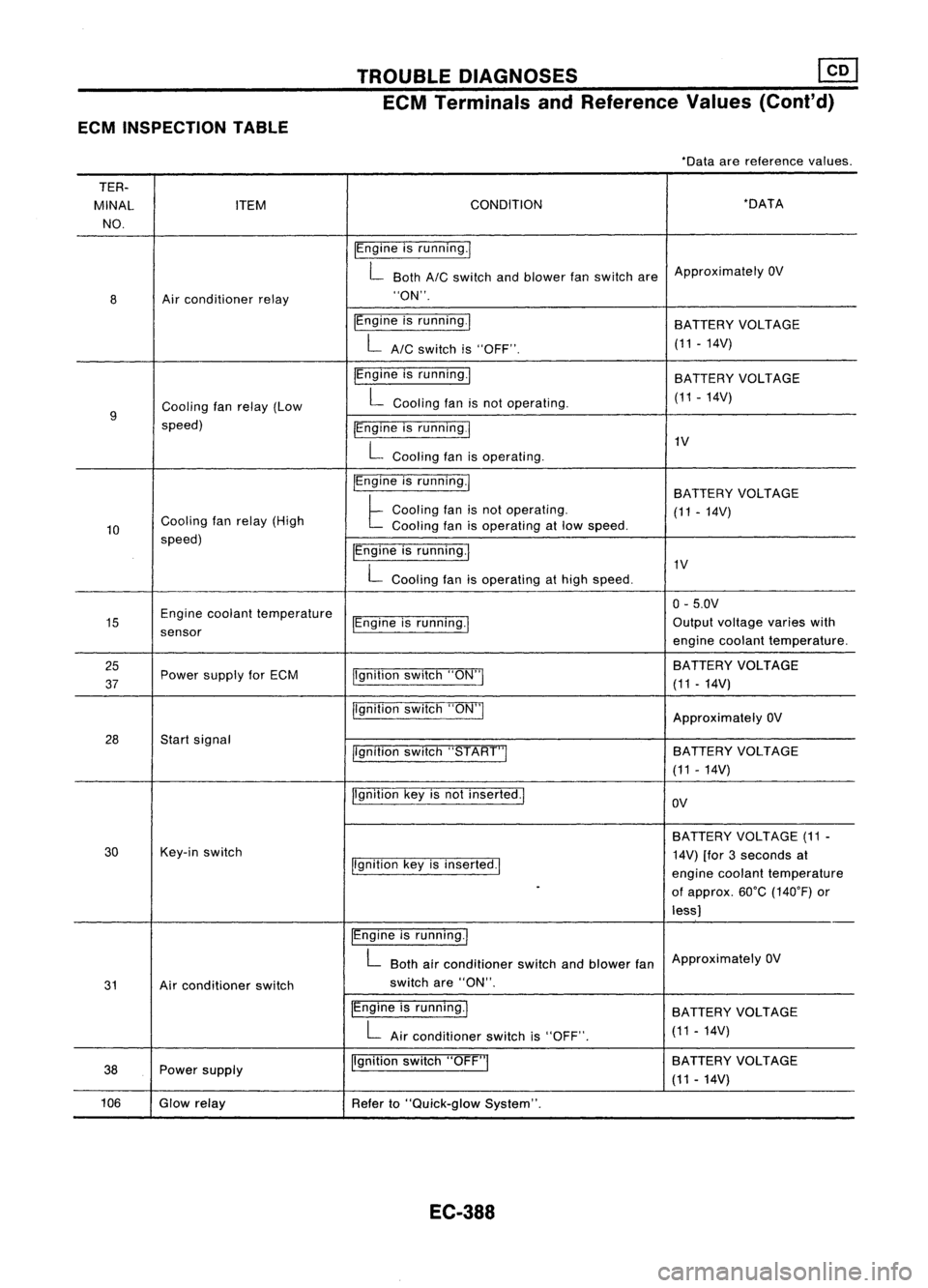
ECMINSPECTION TABLE TROUBLE
DIAGNOSES ~
ECM Terminals andReference Values(Coni'd)
-Data arereference values.
TER-
MINAL ITEM CONDITION -DATA
NO.
IEngineisrunning.1
L Both
AIC
switch andblower fanswitch areApproximately
OV
8 Air
conditioner relay "ON".
IEngine isrunning.1
BATTERYVOLTAGE
LAIC switchis"OFF". (11
-14V)
IEngine isrunning.1
BATTERY VOLTAGE
Cooling fanrelay (Low L
Cooling fanisnot operating. (11-14V)
9
speed) IEngineisrunning
I
L
Cooling fanisoperating. 1V
IEngine isrunning.1
BATTERYVOLTAGE
Cooling fanrelay (High
t
Cooling fanisnot operating.
(11-14V)
10 Cooling
fanisoperating atlow speed.
speed) IEngineisrunning.1
L
Cooling fanisoperating athigh speed. 1V
0- 5.0V
15 Engine
coolant temperature
IEngineisrunning.1 Output
voltage varieswith
sensor enginecoolant temperature.
25 jlgnitionswitch"ON"I BATTERY
VOLTAGE
37 Power
supply forECM
(11-14V)
jlgnition switch"ON"I
ApproximatelyOV
28 Startsignal
llgnitionswitch"START"I SA
TTERY VOLTAGE
(11 -14V)
Ilgnition keyisnot inserted.1
OV
BATTERY VOLTAGE (11-
30 Key-in
switch
14V)[for3seconds at
Ilgnition keyisinserted.1
enginecoolant temperature
-
ofapprox. 60°C(140°F) or
less)
IEngine isrunning.1
L
Both airconditioner switchandblower fanApproximately
OV
31 Airconditioner switch switch
are"ON".
IEngine isrunning.1
BATTERYVOLTAGE
L
Airconditioner switchis"OFF". (11
-14V)
38 Power
supply Ilgnition
switch"OFF"I BATTERY
VOLTAGE
(11 -14V)
106 Glowrelay
Referto"Quick-glow System".
EC-388
Page 1108 of 1701
TROUBLEDIAGNOSES ~
ECM Terminals andReference Values(Cont'd)
*Data arereference values.
TER-
MINAL ITEM CONDITION
*DATA
NO.
IEngineisrunning.1
BATTERYVOLTAGE
L
Engine coolant temperature islower than
(11-14V)
we
(50'F).
108 Solenoid timer
/Engineisrunning.1
L
Engine coolant temperature ishigher than Approximately
OV
we
(50'F).
EC-389
•
Page 1109 of 1701
TROUBLEDIAGNOSES
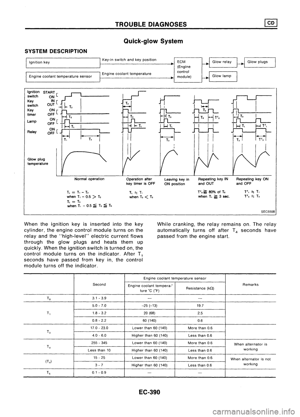
Quick-glow System
SYSTEM DESCRIPTION
Ignition key
Engine coolant temperature sensorKey-in
switch andkeyposition
Engine coolant temperature
ECM
(Engine
control
module) Glow
relay
Glow lamp Glow
plugs
Ignition START[~
~
switch
~~[ I
11
I
1iI
Key
~
switch OUT
-II-
T,
I
!
I
I-l
Key ONe
n
Hn
JTl-
.1"l....!:.1L-
~
timer
OFF
Ir1
To
I
UL
HTo
HT'o
Lamp ON
[
..Lfl
o~~
I
I-.J
TL
I
~
I
I-l
TL
I
I
I
I
I
HTL
I-l
T'L
Relay OFF
[j
I_
L-
r--L
.f"l.-.JL
~
T.
"'
II
I
II
~
1r;,1
I II I
I,
Glow plug
temperature
Normaloperation
Operationafter
key timer isOFF Leaving
keyin
ON position Repeating
keyIN
and OUT Repeating
keyON
and OFF
TL
=
T,-T,
when T,-0.5 >T,
TL
= T,
when T,-0.5 ~T,
;a;
To
TL
=.
T,
when To
<
T, T'o
~80% ofTo
when T.
5':
3sec.
T',
=.
T,
T',
=.
T,
SEC550B
When theignition keyisinserted intothekey
cylinder, theengine control module turnsonthe
relay andthe"high-level" electriccurrentflows
through theglow plugs andheats themup
quickly. Whentheignition switchisturned on,the
control module turnsonthe indicator. AfterT
1
seconds havepassed fromkeyin,the control
module turnsoffthe indicator. While
cranking, therelay remains on.The relay
automatically turnsoffafter T
4
seconds have
passed fromtheengine start.
Engine coolant temperature sensor
Second Enginecoolant tempera-' Remarks
ture 'C('F) Resistance
(kQ)
To
3.1
-3.9
- -
5.0 -7.0 -25(-13)
19.7
T,
1.8
-3.2
20(68)
2.5
0.8 -2.2 60(140)
0.6
17.0 -23.0
Lowerthan
60(140)
Morethan
0.6
T
3
40-6.0
Higherthan
60(140)
Lessthan
0.6
255 -345
Lowerthan
60(140)
Morethan
0.6
Whenalternator is
T
4
working
Less than
10
Higherthan
60(140)
Lessthan
0.6
15 -25
Lowerthan
60(140)
Morethan
0.6
Whenalternator isnot
(T
4)
working
3 -7
Higherthan
60(140)
Lessthan
0.6
T
5
0.1-0.9
- -
EC-390