Page 1369 of 1701
Example(SWITCHCHART)
WIPER SWITCH HOW
TOREAD WIRING DIAGRAMS
Description (Cont'd)
MULTIPLE SWITCH
The continuity ofmultiple switchisdescribed intwo ways as
shown below.
• The switch chartisused inschematic diagrams.
• The switch diagram isused inwiring diagrams.
WIPERSWITCH
f' f
80th switches areturned in
combination.
Continuity circuitofwiper switch
•
SWITCH POSITION
CONTINUITYCIRCUIT
OFF
3-4
INT
3-4,5-6
LO
3-6
HI
2-6
WASH
1-6
SGI875
GI-15
Page 1392 of 1701
IDENTIFICATIONINFORMATION
Identification Number(Cont'd)
IDENTIFICATION PLATE
Europe
NISSAN MOTORCO.,LTD.JAPAN
I
It
I
&,
it
0
ill
iliO
1-
ill
kg
2-
&,
kg
Tri'[
11
COlOR.iRIM
&
&,
TYP
fARBE,POLSl
i
Lilli
Except
Europe
NISSAN MOTORCO.,LTD. JAPAN
~ it
ii:J
b
CHASS~ NO
NO DECHASIS
MODEL
MDDELO
o
~;::~:~~NlctDN
.:t;..-
ENGINE
~:,... MOTOR
~ ';;Y
3;..-
TRANS~
AXl.£
7P;;<'.
ll!AIIS.EJt:
M4DEINJAPAN
o
CC
1
Type approval number
2 Vehicle identification
number (Chassis number)
3 Gross vehicle weight
4 Gross combination weight
Gross vehicle weight
+
Gross trailing capacity
(Weight)
5 Gross axleweight (Front)
6 Gross axleweight (Rear)
7 Type
8 Body colorcode
9 Trim color code
10 Model
11 Engine model
12 Engine displacement
13 Transaxle model
14 Axle model
SGI704
ENGINE SERIALNUMBER
GA 14DE, GA15DE and
GA16DE engine
£~b-=~~rrf~)
(J~~~6
Front
c:::?
SR20DE
engine CD20engine
SGI912
MANUAL TRANSAXLE NUMBER
RS5F30A, RS5F31AandRS5F32A AUTOMATIC
TRANSAXLE NUMBER
SGI913 GI-38 SGI656
Page 1649 of 1701
TROUBLEDIAGNOSES -Supplemental RestraintSystem(SRS)-
Dual AirBag System
Wiring Diagram -SRS -
DUAL AIRBAG SYSTEM
RS-SRS-02
IGNITION SWITCH
ON orSTART
::} ToAS-SAS-D.
•
Refer
toEL-POWER.
LHOmode Is
RHOmodels
@:
GAand SRengine
@:
CDengine
@:
Withtachometer
@:
Without tachometer
~f1 ...
@
30
@
40
,
*2
@
9
@
31
*3
@
16
'@
30
,
AIR
BAG
DIAGNOSIS
SENSOR
UNIT
ill)
FUSE
BLOCK
(JIB)
(M15)
10A
1221
IGN
GNO
~ B
~(ll)
C:J~
B
rn~
I
~g~~~CTOR-3
~:
JOINT
CONNECTOR-4
~~:
I
,..O~O-O-ID-
I
<:
R
:>
I~
B B B BB
1
L..t t.J
~ (M60)~
~
(ll)"
*~
BRIW ~ BRIW-.
COMBINATION BRIW
METER ~
(AIR BAG 111511
WARNING WIL
LAMP)
(M30)
~
10A
W
BIR
.....
~
11*.21
BIR
~----------------------------------~
Refertolast page
(Foldout page).
L ~
em
y
(IT)
y
~(M59):
~P
ITIII:illJIIIII
~:
~ BR
HRS004
RS-29
Page 1660 of 1701

COLLISIONDIAGNOSIS -Dual AirBag System
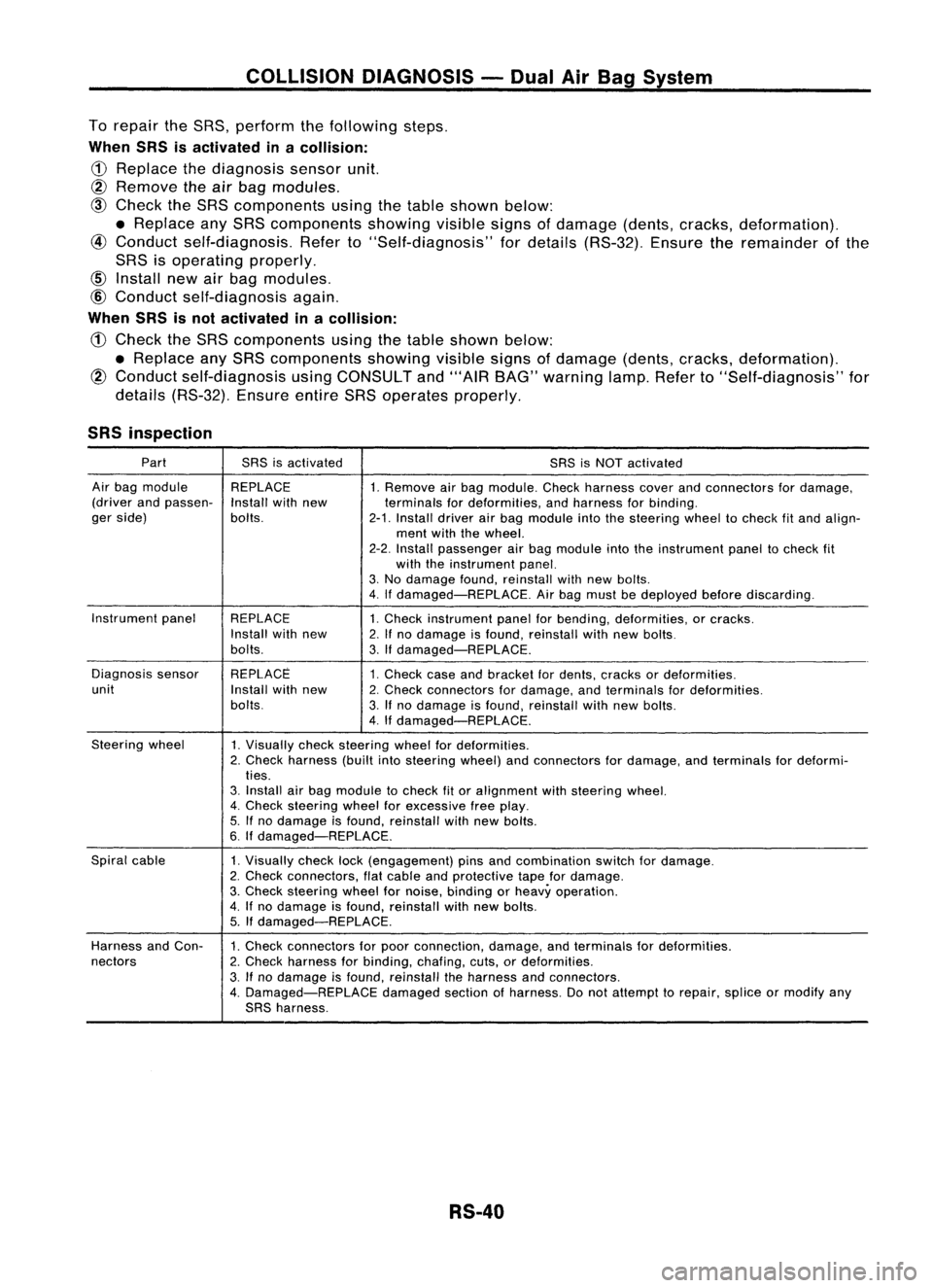
To repair theSRS, perform thefollowing steps.
When SRSisactivated inacollision:
CD
Replace thediagnosis sensorunit.
@ Remove
theairbag modules.
@
Check theSRS components usingthetable shown below:
• Replace anySRS components showing
visible
signsofdamage (dents,cracks, deformation).
@
Conduct self-diagnosis. Referto"Self-diagnosis" fordetails (RS-32). Ensuretheremainder ofthe
SRS isoperating properly.
Install newairbag modules.
@
Conduct self-diagnosis again.
When SRSisnot activated inacollision:
CD
Check theSRS components usingthetable shown below:
• Replace anySRS components showingvisiblesignsofdamage (dents,cracks, deformation).
@
Conduct self-diagnosis usingCONSULT and"'AIR BAG" warning lamp.Referto"Self-diagnosis" for
details (RS-32). EnsureentireSRSoperates properly.
SRS inspection
Part SRSisactivated
SRSisNOT activated
Air bag module REPLACE
1.Remove airbag module. Checkharness coverandconnectors fordamage,
(driver andpassen-
Installwithnew terminalsfordeformities, andharness forbinding.
ger side) bolts.
2-1.Install driverairbag module intothesteering wheeltocheck fitand align-
ment withthewheel.
2-2. Install passenger airbag module intotheinstrument paneltocheck fit
with theinstrument panel.
3. No damage found,reinstall withnewbolts.
4. Ifdamaged-REPLACE. Airbag must bedeployed beforediscarding.
Instrument panel
REPLACE 1.Check instrument panelforbending, deformities, orcracks.
Install withnew
2.Ifno damage isfound, reinstall withnewbolts.
bolts. 3.Ifdamaged-REPLACE.
Diagnosis sensor REPLACE
1.Check caseandbracket fordents, cracks ordeformities.
unit Installwithnew
2.Check connectors fordamage, andterminals fordeformities.
bolts. 3.Ifno damage isfound, reinstall withnewbolts.
4. Ifdamaged-REPLACE.
Steering wheel
1.Visually checksteering wheelfordeformities.
2. Check harness (builtintosteering wheel)andconnectors fordamage, andterminals fordeformi-
ties.
3. Install airbag module tocheck fitor alignment withsteering wheel.
4. Check steering wheelforexcessive freeplay.
5. Ifno damage isfound, reinstall withnewbolts.
6. Ifdamaged-REPLACE.
Spiral cable
1.Visually checklock(engagement) pinsandcombination switchfordamage.
2. Check connectors, flatcable andprotective tapefordamage.
3. Check steering wheelfornoise, binding orheavy operation.
4. Ifno damage isfound, reinstall withnew bolts.
5. Ifdamaged-REPLACE.
Harness andCon-
1.Check connectors forpoor connection, damage,andterminals fordeformities.
nectors 2.Check harness forbinding, chafing,cuts,ordeformities.
3. Ifno damage isfound, reinstall theharness andconnectors.
4. Damaged-REPLACE damagedsectionofharness. Donot attempt torepair, spliceormodify any
SRS harness.
RS-40
Page 1664 of 1701

TROUBLEDIAGNOSES -Supplemental RestraintSystem(SRS)
Single AirBag System
Self-diagnosis (Cont'd)
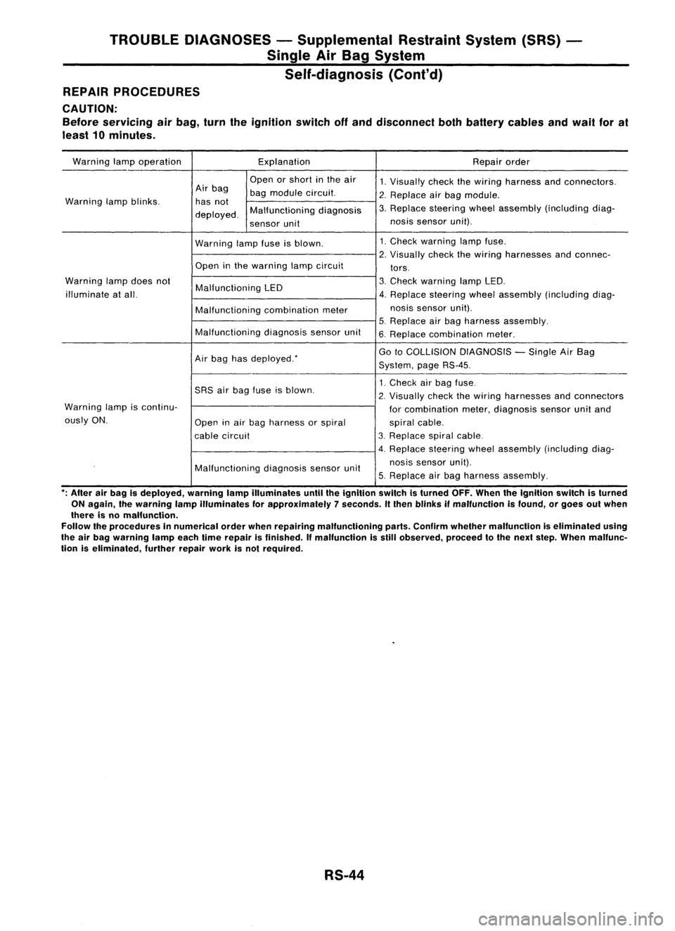
REPAIR PROCEDURES
CAUTION:
Before servicing airbag, turntheignition switchoffand disconnect bothbattery cablesandwail forat
least 10minutes.
Warning lampoperation Explanation
Repairorder
Open orshort inthe air
1.Visually checkthewiring harness andconnectors.
Air bag
bagmodule circuit.
2.Replace airbag module.
Warning lampblinks. hasnot
3.Replace steering wheelassembly (including diag-
deployed. Malfunctioning
diagnosis
sensor unit nos
issensor unit).
Warning lampfuseisblown. 1.
Check warning lampfuse.
2. Visually checkthewiring harnesses andconnec-
Open inthe warning lampcircuit
tors.
Warning lampdoes not
Malfunctioning LED 3.
Check warning lampLED.
illuminate atall. 4.Replace steering wheelassembly (including diag-
Malfunctioning combinationmeter nos
issensor unit).
5. Replace airbag harness assembly.
Malfunctioning diagnosissensorunit
6.Replace combination meter.
Air bag hasdeployed: Go
toCOLLISION DIAGNOSIS -Single AirBag
System, pageRS-45.
1. Check airbag fuse.
SRS airbag fuse isblown.
2.
Visually checkthewiring harnesses andconnectors
Warning lampiscontinu-
forcombination meter,diagnosis sensorunitand
ously ON.
Openinair bag harness orspiral
spiralcable.
cable circuit 3.
Replace spiralcable.
4. Replace steeringwheelassembly (including diag-
Malfunctioning diagnosissensorunit nosis
sensor unit).
5. Replace airbag harness assembly.
*;
After airbag isdeployed, warninglampilluminates untiltheignition switchisturned OFF.When theIgnition switchisturned
ON again, Ihewarning lampilluminates forapproximately 7seconds. Itthen blinks ifmalfunction isfound, orgoes outwhen
there isno malfunction.
Follow theprocedures innumerical orderwhenrepairing malfunctioning parts.Confirm whether malfunction iseliminated using
the airbag warning lampeachtimerepair isfinished. Ifmalfunction isstill observed, proceedtothe next step. When malfunc-
tion iseliminated, furtherrepairworkisnot required.
RS-44
Page 1675 of 1701
STEERINGWHEELANDSTEERING COLUMN
Removal andInstallation
SEC. 484.487.488
_~ ~4.0-4.9 (0.4 -0.5, 35-43)
ij] :
N.m (kg-m, in-Ib)
co;J :
N.m (kg-m. ft-Ib) With
airbag
Withoutairbag
SST538C
G)
Airbag module
@
Horn pad
@
Steering wheel
@
Spiral cable
@
Column cover
@
Combination switch
(J)
Steering columnassembly
@
Lower joint
@
Boot
CAUTION (SRSmodels only): •
• The rotation ofthe spiral cable(SRS"Airbag" component
part) islimited. Ifthe steering gearmust beremoved, set
the front wheels inthe straight-ahead direction.Donot
rotate thesteering columnwhilethesteering gearis
removed.
• Remove thesteering wheelbefore removing thesteering
lower jointtoavoid damaging theSRS spiral cable.
STEERING WHEEL
With AirBag
• Remove airbag module andspiral cable.
Refer to"Removal -Air Bag Module andSpiral Cable",
"SUPPLEMENTAL RESTRAINTSYSTEM"inRS section.
SBF812E ST-9
Page 1678 of 1701
SEC.488 STEERING
WHEELANDSTEERING COLUMN
Disassembly andAssembly
~.N.m (kg-m, in-Ib)
~ .N.m (kg-m, ft-Ib)
SST539C
G)
Spiral cable
@
Combination switch
@
Lock nut
@
Tiltlever
@
Washer
@
Tiltlever stopper
!J)
Steering columnmounting
bracket
@
Adjust bolt
CID
Adjust boltstopper
@J
Push nut
@
Jacket tubeassembly
@
Boot
@
Steering columnshaft
@
Lower joint
@
Return spring
Lock nut
II
I
•
When disassembling andassembling, unlocksteering lock
with key.
• Install locknutonsteering columnshaftandtighten thenut
to specification.
~: 25-34 N.m (2.5-3.5 kg-m, 18-25 ft-Ib)
SST490C ST-12