Page 514 of 1701
WARNINGLAMPSANDBUZZER
Warning Lamps/Wiring Diagram-WARN -
(Cont'd)
WASHER
FLUID
LOW LEVEL
SWITCH
HIGH-- ~
~
a
I
f.
S B
-!- -!-
~ @D
EL-WARN-04
@:
5-door Hatchback and
Sedan models
COMBINATIONMETER~
Preceding C
page
DOORWASHER
~ ~
RIW
alP
(!J~NCTI~
BOXNO.2
(JOINT
CONNECTORS)
~~
SIP
;h@
luiEll
(MS)
[IJ(]g)
RIW SIP
~
I
• ~
0
•
OPEN OPEN
OPENOPEN
...... _- ......_- ......
_-
......_-
CLOSED CLOSEDCLOSED
CLOSED
REAR REARFRONT
FRONT
DOOR
-
DOOR
-
DOOR
-
DOOR
-
SWITCH SWITCH
SWITCH
SWITCH
LH RH
PASSENGER
DRIVER'S
~:@ ~:@
SIDE
smE
(@)
@)
&~GID
56TII91Q1112 W
~@
l.1.@ B
Refer
tolast page
(Foldout page).
CMID
(M19)
~~(@)
[l
SR'BR 'SR
rfi2l@)
N
a
HEL074
EL-142
Page 518 of 1701
WARNINGLAMPSANDBUZZER
Warning Lamps/Wiring Diagram-WARN -
(Coni' d)
EL-WARN-08
@:
5-door Hatchback and
Sedan models
COMBINATIONMETER
~
@:
Except forAustralia
PrecedingF
page
DOORWASHER
U3i
I
~
RIW B/P
m
JOINT
CONNECTOR-1
@
~
B/P
~(M6)
,t,
(MS)
[jJ(]ID
RIW B/P
~
I
• ~
0
•
WASHER
FLUID
LOW LEVEL
SWITCH
@:@
~ B
I
r.
B 8
~ ~
~
,--
HIGH
OPEN OPEN
OPENOPEN
'-- '--'--
,--
CLOSED CLOSED
CLOSEDCLOSED
REAR REARFRONT FRONT
DOOR
-
DOOR
-
DOOR
-
DOOR
-
SWITCH SWITCHSWITCH SWITCH
LH RHPASSENGER
DRIVER'S
~:<@)
@:@
SIDE
SIDE
~
(][)
Fa@
I.1l£J
B
Refer
tolast page
(Foldout page).
@ ~
~@~
E!l
BR' BR'BR
rfi2l
(89)
m B
HEL078
EL-146
Page 520 of 1701
WARNINGLAMPSANDBUZZER
Warning Lamps/Wiring Diagram-WARN -
(Cont'd)
EL-WARN-10
COMBINATION
METER
@)@>
LHD models
RHD models
Models withdual
air bag system
Models withsingle
air bag system
(D:
(8):
@:
@:
B
-!
(E205)
~
Y/R
•
o~
R Y/R
rn
2
JOINT
CONNECTOR-1
~
I!:jJJ
Y/R
I"UD\
Y/R
I'TIO\
I$II~ ~~
IlJI
Y/R Y/R
t.o.i
I
Y/R ~
.-4-,~
~
ViR ~
O
L
ALTERNATOR
E @ID @ID
~
BR/W~
I~I@)
BR/W
BR/W
O~
AIRBAG
111511 DIAGNOSIS
W/L SENSOR
UNIT
(Refer to
RS-SRS.).
em
G
SPIRAL
CABLE
~
BR/W
•
t-:lDiAA:---.
It
BR/W
I"UD\
BR/W
I'TIO\
1i1tn~~~
!!JI
I
3.G
I
BR/W BR/W
t~
I
BR/W
m~
B/R
~
~-------------------------------,
~-------------------------------~
Refer
tolast page
(Fo ldout page).
@
ITlIIillIillIII
@
~ BR
~~
~B
~-------------.,
~@
[g]lJTIJ
W
:
~ :
IrnGY ~I
I I
L
.J
HEL080
EL-148
Page 521 of 1701
WARNINGLAMPSANDBUZZER
Warning Lamps/Wiring Diagram-WARN -
(Cont'd)
EL-WARN-11
•
PARKING
SRAKE
SWITCH
~
Refer tolast page
(Foldout page).
(Me) (E1Ot)
(fill)
,--
RELEASED
:
LHDmode 1s
@:
RHOmodels
RHOmodels forEurope
<@):
Except
*5 ...
20([) 1
.
COMBINATION
METER
~
BRAKE
NR
H
LOW
~
Y/B
.... I
o
+
~Y:: NR
*~Y/B---~O
JUNCTION BOXNO.2
I
I
*.5
I
(JOINT CONNECTORS)
Y/B~:
~ JOINT CONNECTOR-5
O-
~@):@
.... ~ ~@)
Y/B
I
-----D-O
ICiJI@
I$I(~:;
~ Y/BY/S
I~I ~
I$I
CMID
I
T--
.,... ~ m ----.~
I
Y/B Y/S
m
ctJ
Y/B
BRAKE BRAKE ~
FLUID FLUID II1II
~~~~EH '--~~~~EH
n
~ HIGH ~
~ Ef1"
I
'~O
l!-
III, ~
ffi
(E51)
Preceding
page
,--
HIGH
~@)
~OR m@
m
GY
t1\@
tgj
GY
R
(B14)
W
B
HEL081
EL-149
Page 523 of 1701

Ohmmeter- + WARNING
LAMPSANDBUZZER
Oil Pressure SwitchCheck
Oil pressure
Continuity
kPa (bar, kg/cm
2,
psi)
More than10-20
NO
Engine
start
(0.10-0.20, 0.1-0.2, 1.4-2.8)
Less than10-20
YES
Engine
stop
(0.10-0.20, 0.1-0.2, 1.4-2.8)
SEL748K
Test lamp 3.4WON
\ ,I
"
/
Ballery
Test lamp 3.4W OFF
~0
CD
Ballery
Gasoline MEL623D
SEL901F
Check
thecontinuity betweentheterminals ofoil pressure
switch andbody ground.
Fuel Warning LampSensor Check
• Itwill take ashort timeforthe bulb tolight.
Diode Check
• Check continuity usinganohmmeter.
• Diode isfunctioning properlyiftest results areasshown in
the figure atleft.
NOTE:
Specification mayvary depending onthe type oftester. Before
performing thisinspection, besure torefer tothe instruction
manual forthe tester tobe used.
• Diodes forwarning lampsarebuilt intothecombination
meter printed circuit.
Refer to"Combination Meter"(EL-127).
Warning BuzzerUnit
• Seat beltwarning lampiscontrolled bythe warning buzzer
unit.
Refer to"Warning Buzzer"(EL-152).
EL-151
•
Page 532 of 1701

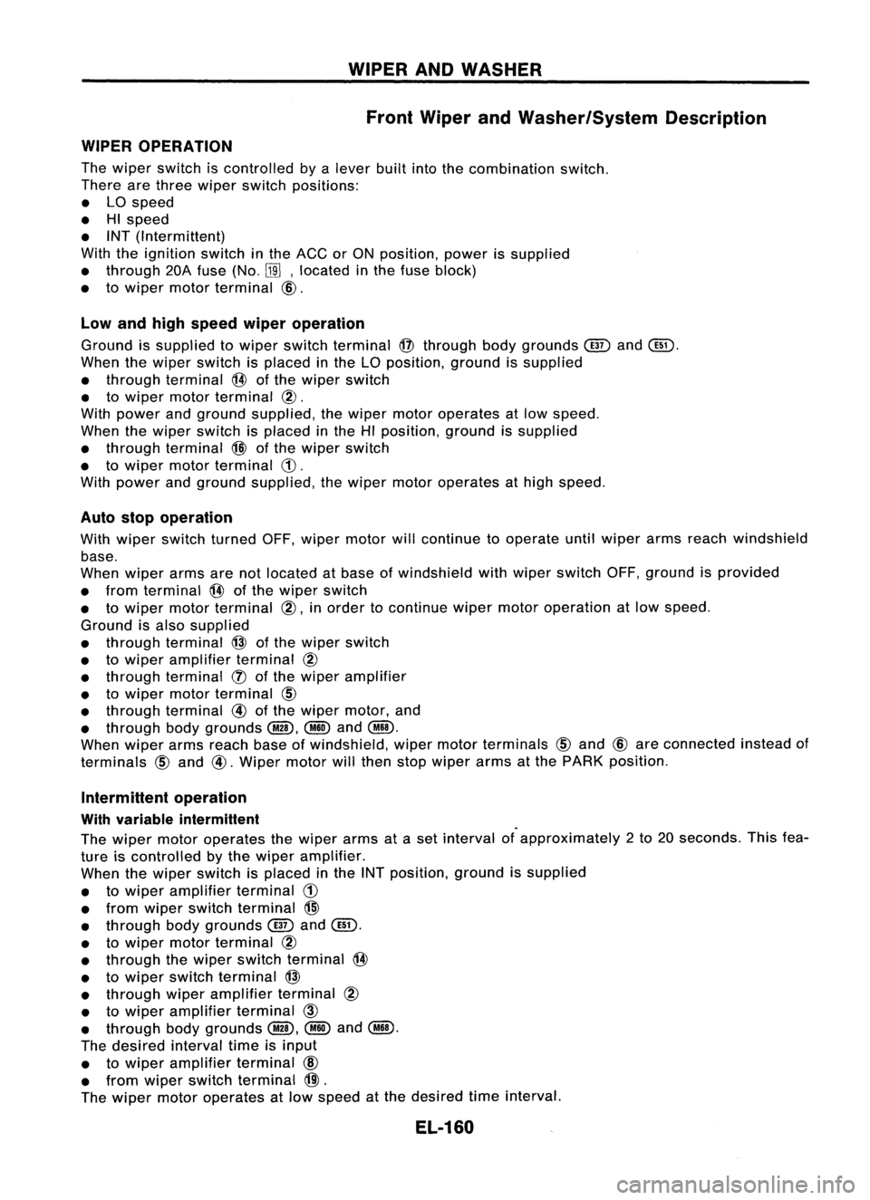
WIPERANDWASHER
Front Wiper andWasher/System Description
WIPER OPERATION
The wiper switch iscontrolled bya
lever
builtintothecombination switch.
There arethree wiper switch positions:
• LOspeed
• HIspeed
• INT (Intermittent)
With theignition switchinthe ACC orON position, powerissupplied
• through 20Afuse (No.
BID,
located inthe fuse block)
• towiper motor terminal
CID.
Low andhigh speed wiperoperation
Ground issupplied towiper switch terminal
@
through bodygrounds
(ill)
and
@.
When thewiper switch isplaced inthe LOposition, groundissupplied
• through terminal
@
ofthe wiper switch
• towiper motorterminal
@.
With power andground supplied, thewiper motor operates atlow speed.
When thewiper switch isplaced inthe HIposition, groundissupplied
• through terminal
@
ofthe wiper switch
• towiper motor terminal
(j).
With power andground supplied, thewiper motoroperates athigh speed.
Auto stopoperation
With wiper switch turned OFF,wiper motor willcontinue tooperate untilwiper armsreach windshield
base.
When wiper armsarenotlocated atbase ofwindshield withwiper switch OFF,ground isprovided
• from terminal
@
ofthe wiper switch
• towiper motorterminal @,inorder tocontinue wipermotoroperation atlow speed.
Ground isalso supplied
• through terminal
@
ofthe wiper switch
• towiper amplifier terminal
@
• through terminal
(J)
ofthe wiper amplifier
• towiper motorterminal
@)
• through terminal
@
ofthe wiper motor, and
• through bodygrounds
@,
@
and
@.D.
When wiper armsreach baseofwindshield, wipermotor terminals
@)
and
CID
are connected insteadof
terminals
@)
and
@.
Wiper motorwillthen stopwiper armsatthe PARK position.
Intermittent operation
With variable intermittent
The wiper motor operates thewiper armsataset interval ofapproximately 2to 20 seconds. Thisfea-
ture iscontrolled bythe wiper amplifier.
When thewiper switch isplaced inthe INT position, groundissupplied
• towiper amplifier terminal
(j)
• from wiper switch terminal
@
• through bodygrounds
(ill)
and
@.
• towiper motorterminal
@
• through thewiper switch terminal
@
• towiper switch terminal
@
• through wiperamplifier terminal
@
• towiper amplifier terminal
CID
• through bodygrounds
@,
@
and
@.D.
The desired intervaltimeisinput
• towiper amplifier terminal
@
• from wiper switch terminal
@).
The wiper motoroperates atlow speed atthe desired time
interval.
EL-160
Page 541 of 1701

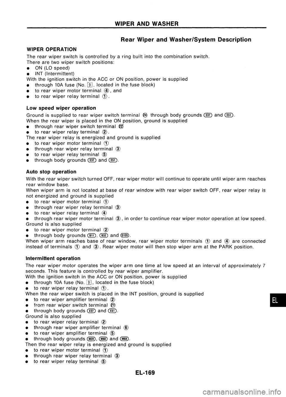
WIPERANDWASHER
Rear Wiper andWasher/System Description
WIPER OPERATION
The rear wiper switch iscontrolled byaring built intothecombination switch.
There aretwo wiper switch positions:
• ON (LO speed)
• INT (Intermittent)
With theignition switchinthe ACC orON position, powerissupplied
• through 10Afuse (No.
W,
located inthe fuse block)
• torear wiper motorterminal
@,
and
• torear wiper relayterminal
CD.
Low speed wiperoperation
Ground issupplied torear wiper switch terminal
@
through bodygrounds
@
and
Cill).
When therear wiper isplaced inthe ON position, groundissupplied
• through rearwiper switch terminal
@
• torear wiper relayterminal
@.
The rear wiper relayisenergized andground issupplied
• torear wiper motor terminal
CD
• through rearwiper relayterminal
CID
• torear wiper relayterminal
CID
• through bodygrounds
@
and
Cill).
Auto stopoperation
With therear wiper switch turned OFF,rearwiper motor willcontinue tooperate untilwiper armreaches
rear window base.
When wiperarmisnot located atbase ofrear window withrearwiper switch OFF,rearwiper relayis
not energized andground issupplied
• torear wiper motorterminal
CD
• through rearwiper relayterminal
CID
• torear wiper relayterminal
@
• through rearwiper motor terminal
CID,
inorder tocontinue rearwiper motoroperation atlow speed.
Ground isalso supplied
• torear wiper motor terminal
@
• through bodygrounds
Cill),
@
and
(Qill).
When wiperarmreaches baseofrear window, rearwiper motorterminals
CD
and
@
are connected
instead ofterminals
CD
and
CID.
Rear wiper motor willthen stopwiper armatthe PARK position.
Intermittent operation
The rear wiper motor operates thewiper armonetime atlow speed atan interval ofapproximately 7
seconds. Thisfeature iscontrolled byrear wiper amplifier.
With theignition switchinthe ACC orON position, powerissupplied
• through 10Afuse (No.
W,
located inthe fuse block)
• torear wiper relayterminal
CD.
When therear wiper switch isplaced inthe INT position, groundissupplied •
• torear wiper amplifier terminal
@
• from rearwiper switch terminal
@
• through bodygrounds
@
and
Cill).
Ground isalso supplied
• torear wiper relayterminal
@
• through rearwiper amplifier terminal
@
• torear wiper amplifier terminal
CID
• through bodygrounds
@,
@ID
and
@.
Then therear wiper relayisenergized andground issupplied
• torear wiper motorterminal
CD
• through rearwiper relayterminal
CID
• torear wiper relayterminal
CID
EL-169
Page 599 of 1701
HORN,CI(;ARETTE LIGHTERANDCLOCK
Wiring Diagram -HORN -(Cont'd)
EL-HORN-02
•
FUSE
Referto
BLOCK EL-POWER.
(JIB)
~
Refer tolast page
(Foldout page).
COMBINATION
METER
@
~
7.5A
1241
~
BIR
P
IF!4il
BIR
!
@)
OIGITAL
CLOCK
15A
[]Q]
CLOCK ILLUMI-
NATION
L
~
~ B
•
CIGARETTE
LIGHTER SOCKET
@
15A
[TI]
r-----------------------------------,
1ITl~
[]] B
@:
Withtachometer
@:
Without tachometer
*3"'@ 34
@
5
*4 ... @28
'@
6
*5' ..@29
'@10
*6"'@ 9
'@31
,
I
N;.21
OR/B
I
CIGARETTE OR/B
LIGHTER ~
~ 10-----.:
~B
l-,
I
B B
~1
ffi
JOINT
CONNECTOR-1
~
Ibi=Jl
B
I
f,
B B
! !
(M28) (M68)
L ~
IIIIIillIITillI
@
~BR
HEL133
EL-227