1995 NISSAN ALMERA N15 Combination
[x] Cancel search: CombinationPage 177 of 1701
REPLACEMENTOPERATIONS
Rear Floor Rear ________
GENERALINFORMATION _
Identification Number(Cont'd)
(Work afterrearpanel havebeen removed.)
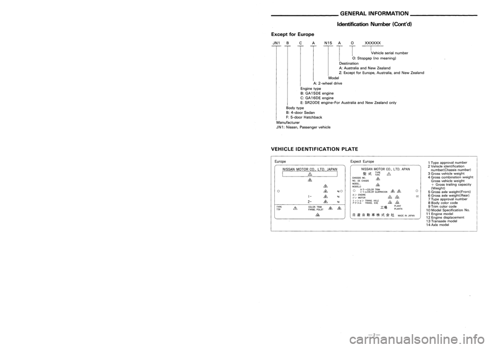
ExceptforEurope
IN 1 .B CAN 15A
0
XXXXXX
T
T
--c:::
serialnumber
0:
Stopgap (nomeaning)
Destination
A: Australia andNew Zealand
Z: Except forEurope, Australia, andNew Zealand
Model
A: 2-wheel drive
Engine type
B: GA 15DE engine
C: GA 16DE engine
E: SR20DE engine-For AustraliaandNew Zealand only
Body type
B: 4-door Sedan
F: 5-door Hatchback
Manufacturer
IN 1:Nissan, Passenger vehicle
VEHICLE IDENTIFICATION PLATE
1Type approval number
2 Vehicle identification
number(Chassis number)
3 Gross vehicle weight
4 Gross combination weight
Gross vehicle weight
+
Gross trailing capacity
(Weight)
5 Gross axleweight(Front)
6 Gross axleweight(Rear)
7 Type approval number
8 Body colorcode
9 Trim color code
10 Model Specification No.
11 Engine model
12 Engine displacement
13 Transaxle model
14 Axle model
cc
o
PLANT
PlANTA
El
ii:
13IJJ
if[
**
it~
*1
MADEINJAPAN
NISSAN
MOTORCO.,LTD. APAN
~ tt
~(:l
&
~~~sg~
CNHOA"SIS ~
~~~~~o
&
o ~
0
:ggtg~
~~~RNICION ~
&.
~~ ~~~~~ &
£
; ;~)~ /~~~~~'. AE~~
A1L11
Expect
Europe
~
&
kgO
1-
&
kg
2-
&
kg
COlOR. TRIM
~
&
FARBE. POlST
&
NISSAN
MOTORCO.,LTD. JAPAN
I ~ I
~
o
TYPE
TTP
Europe
FR
_2
3D
HI
B:3door hatchback
5D
HI
B:5door hatchback
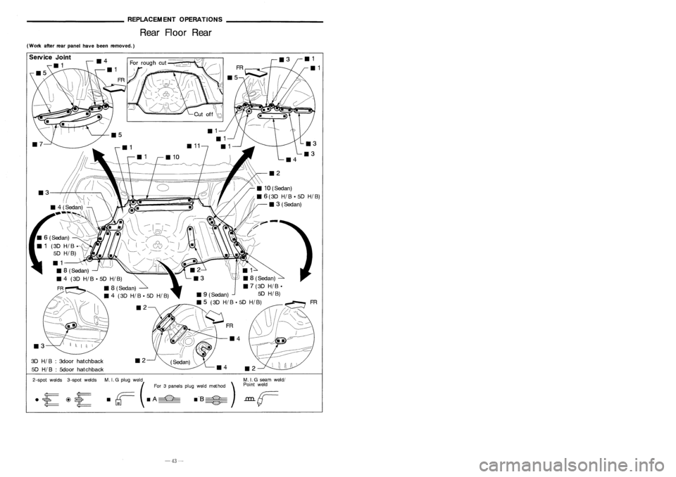
Service
Joint
111
~
2-spot welds 3-spotwelds M.
I.
G plug weld .MIG seam weld/
(For 3panels plugweld method )P:
F
weld
• rr=- •
A
===-=
.'S~
.L.LLL
GTJ --- ~
-43-
-2-
Page 194 of 1701
__________ BODYALIGNMENT _
_HANDLINGPRECAUTIONS FORPLASTICS _
Passenger Compartment Sedan
5-door Hatchback Location
OfPlastic Parts
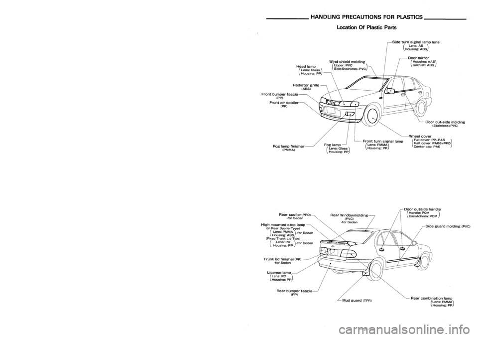
Side turnsignal lamplens
(Lens: AS)
Housing: ASS
Wind-shield molding
(Upper: PVC )
Side:Stainless+PVC
Doorout-side molding
(Stainless+PVC)
Wheel cover
(Full cover: PP+PA6 )
Half cover: PA66+PPO
Center cap:PA6
Door
mirror
(Housing: AAS)
Garnish: ASS
Front turnsignal lamp
(Lens: PMMA)
Housing: PP
Fog
lamp
(Lens: Glass)
Housing: PP
Head
lamp
(Lens: Glass)
Housing: pp
Radiator grille
(ABS)
Fog lamp finisher
(PM MA)
Front
bumper fascia
(PP)
Front airspoiler
(PP)
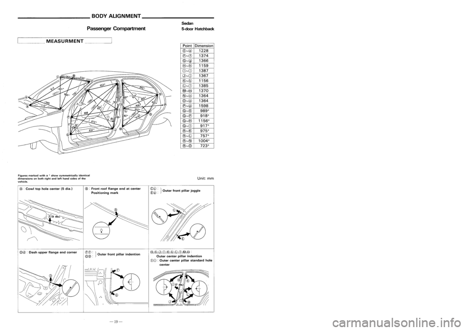
Point
Dimension
@-@
1228
CB-
@-@
1366
(8)-{6)
1159
CD--cD
1387
Q)-{J) 1367
@--@
1156
(b)--{[)
1385
~-4iV
1370
@~
1364
@~
1364
C'e)--@
1598
@--@
989*
@-{E)
918*
@~
1156*
@--{[)
917*
@~@
975*
@~(b)
757*
@~
1004*
@--@
723*
,
... ._MEASURMENT _
Figures marked witha
*
show symmetrically identical
dimensions onboth right andlefthand sides ofthe
vehicle.
Unit:
mm
@ :
Cowl tophole center (5dia.)
CB>
:
Front roofflange endatcenter
Positioning mark ~~
~}Outer frontpillarjoggle
Sideguard molding (PVC)
Rear combination lamp
(Lens: PMMA)
Housing: PP
Door
outside handle
(Handle: POM )
Escutcheon: POM
Mud guard (TPR)
Rear
Windowmolding
(PVC)
-for Sedan
Rear bumper fascia
(PP)
License
lamp
(Lens: PC)
Housing: PP
Trunk
lidfinisher(pp)
-for Sedan
Rear
spoiler(PPO)
-for Sedan
High mounted stoplamp
(In Rear SpoilerType)
(Lens: PMMA)-for Sedan
Housing: ASS
(Fixed Trunk LidTipe)
(Lens: PC)-for Sedan
Housing: PP
(f3),Cfi),Q),CD,@,@,CD,CD,~,@ :
Outer center pillarindention
CDCD :
Outer center pillarstandard hole
center
CBCD:
}
~@:
Outerfrontpillar indention
@@
:
Dash upper flange endcorner
-19- -26-
Page 201 of 1701
__________ BODYALIGNMENT _
_HANDLINGPRECAUTIONS FORPLASTICS _
Passenger Compartment Sedan
5-door Hatchback Location
OfPlastic Parts
Side turnsignal lamplens
(Lens: AS)
Housing: ASS
Wind-shield molding
(Upper: PVC )
Side:Stainless+PVC
Doorout-side molding
(Stainless+PVC)
Wheel cover
(Full cover: PP+PA6 )
Half cover: PA66+PPO
Center cap:PA6
Door
mirror
(Housing: AAS)
Garnish: ASS
Front turnsignal lamp
(Lens: PMMA)
Housing: PP
Fog
lamp
(Lens: Glass)
Housing: PP
Head
lamp
(Lens: Glass)
Housing: pp
Radiator grille
(ABS)
Fog lamp finisher
(PM MA)
Front
bumper fascia
(PP)
Front airspoiler
(PP)
Point
Dimension
@-@
1228
CB-
@-@
1366
(8)-{6)
1159
CD--cD
1387
Q)-{J) 1367
@--@
1156
(b)--{[)
1385
~-4iV
1370
@~
1364
@~
1364
C'e)--@
1598
@--@
989*
@-{E)
918*
@~
1156*
@--{[)
917*
@~@
975*
@~(b)
757*
@~
1004*
@--@
723*
,
... ._MEASURMENT _
Figures marked witha
*
show symmetrically identical
dimensions onboth right andlefthand sides ofthe
vehicle.
Unit:
mm
@ :
Cowl tophole center (5dia.)
CB>
:
Front roofflange endatcenter
Positioning mark ~~
~}Outer frontpillarjoggle
Sideguard molding (PVC)
Rear combination lamp
(Lens: PMMA)
Housing: PP
Door
outside handle
(Handle: POM )
Escutcheon: POM
Mud guard (TPR)
Rear
Windowmolding
(PVC)
-for Sedan
Rear bumper fascia
(PP)
License
lamp
(Lens: PC)
Housing: PP
Trunk
lidfinisher(pp)
-for Sedan
Rear
spoiler(PPO)
-for Sedan
High mounted stoplamp
(In Rear SpoilerType)
(Lens: PMMA)-for Sedan
Housing: ASS
(Fixed Trunk LidTipe)
(Lens: PC)-for Sedan
Housing: PP
(f3),Cfi),Q),CD,@,@,CD,CD,~,@ :
Outer center pillarindention
CDCD :
Outer center pillarstandard hole
center
CBCD:
}
~@:
Outerfrontpillar indention
@@
:
Dash upper flange endcorner
-19- -26-
Page 218 of 1701
REPLACEMENTOPERATIONS
Rear Floor Rear ________
GENERALINFORMATION _
Identification Number(Cont'd)
(Work afterrearpanel havebeen removed.)
ExceptforEurope
IN 1 .B CAN 15A
0
XXXXXX
T
T
--c:::
serialnumber
0:
Stopgap (nomeaning)
Destination
A: Australia andNew Zealand
Z: Except forEurope, Australia, andNew Zealand
Model
A: 2-wheel drive
Engine type
B: GA 15DE engine
C: GA 16DE engine
E: SR20DE engine-For AustraliaandNew Zealand only
Body type
B: 4-door Sedan
F: 5-door Hatchback
Manufacturer
IN 1:Nissan, Passenger vehicle
VEHICLE IDENTIFICATION PLATE
1Type approval number
2 Vehicle identification
number(Chassis number)
3 Gross vehicle weight
4 Gross combination weight
Gross vehicle weight
+
Gross trailing capacity
(Weight)
5 Gross axleweight(Front)
6 Gross axleweight(Rear)
7 Type approval number
8 Body colorcode
9 Trim color code
10 Model Specification No.
11 Engine model
12 Engine displacement
13 Transaxle model
14 Axle model
cc
o
PLANT
PlANTA
El
ii:
13IJJ
if[
**
it~
*1
MADEINJAPAN
NISSAN
MOTORCO.,LTD. APAN
~ tt
~(:l
&
~~~sg~
CNHOA"SIS ~
~~~~~o
&
o ~
0
:ggtg~
~~~RNICION ~
&.
~~ ~~~~~ &
£
; ;~)~ /~~~~~'. AE~~
A1L11
Expect
Europe
~
&
kgO
1-
&
kg
2-
&
kg
COlOR. TRIM
~
&
FARBE. POlST
&
NISSAN
MOTORCO.,LTD. JAPAN
I ~ I
~
o
TYPE
TTP
Europe
FR
_2
3D
HI
B:3door hatchback
5D
HI
B:5door hatchback
Service
Joint
111
~
2-spot welds 3-spotwelds M.
I.
G plug weld .MIG seam weld/
(For 3panels plugweld method )P:
F
weld
• rr=- •
A
===-=
.'S~
.L.LLL
GTJ --- ~
-43-
-2-
Page 233 of 1701
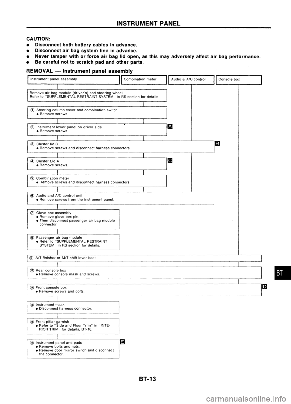
INSTRUMENTPANEL
CAUTION:
• Disconnect bothbattery cablesinadvance.
• Disconnect airbag system lineinadvance.
• Never tamper withorforce airbag lidopen, asthis may adversely affectairbag performance.
• Becareful nottoscratch padandother parts.
REMOVAL -Instrument panelassembly
Instrument panelassembly
Remove airbag module (driver's) andsteering wheel.
Refer to"SUPPLEMENTAL RESTRAINTSYSTEM"inRS section fordetails.
CD
Steering columncoverandcombination switch
• Remove screws.
l6l
Instrument lowerpanel ondriver side
• Remove screws.
@
Cluster lidC
• Remove screwsanddisconnect harnessconnectors. Audio
&AIC
control
Consolebox
@
Cluster lidA
• Remove screws.
@
Combination meter
• Remove screwsanddisconnect harnessconnectors.
cID
Audio and
AIC
control unit
• Remove screwsfromtheinstrument panel.
(J)
Glove boxassembly
• Remove gloveboxpin.
• Then disconnect passengerairbag module
connector.
@
Passenger airbag module
• Refer to"SUPPLEMENTAL RESTRAINT
SYSTEM" inRS section fordetails.
@
AIT
finisher orMIT shift lever boot
@
Rear console box
• Remove consolemaskandscrews.
@
Front console box
• Remove screwsandbolts.
@
Instrument mask
• Disconnect harnessconnector.
@
Front pillargarnish
• Refer to"Side andFloor Trim" in"INTE-
RIOR TRIM" fordetails, 8T-16.
@
Instrument panelandpads
II
• Remove boltsandnuts.
• Remove doormirror switch anddisconnect
the connector.
•
8T-13
Page 252 of 1701
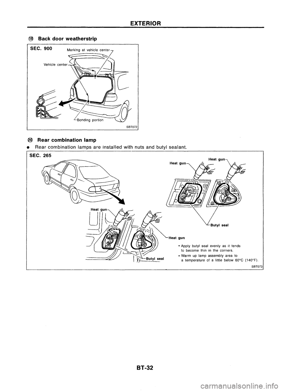
@l
Back doorweatherstrip
SEC. 900
Vehicle center
Bondingportion
SBT072
@
Rear combination lamp.
dithnuts andbutyl sealant.
b' ation lamps areInstalle
w
• Rear com In
SEC. 265
BT-32
Page 315 of 1701
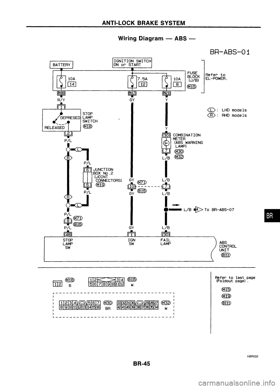
ANTI-LOCKBRAKESYSTEM
Wiring Diagram -ABS -
BR-ABS-01
•
ABS
CONTROL
UNIT
(B111)
LHDmodels
@:
RHOmodels
Refer
to
EL-POWER.
FUSE
BLOCK
(JIB)
~
GY
ffi
IGN
SW
Y
I~I COMBINATION
METER
(ABS WARNING
LAMP)
~@
LIB
@
I
GY
$-------$
GY (~) LIB
I-
e-
LIB~ ToBR-ABS-O?
I
LIB
13-0
I
FAIL
LAMP
IGNITION
SWITCH
ON orSTART
STOP
DEPRESED LAMP
SWITCH
RELEASED ~
~
P!L
•
~:I
P!L
rn~
I
JUNCTION
BOX
NO.2
(JOINT
CONNECTORS)
1!:i=!J~
PIL
~~
•
PIL
lelIl
9F'~
P!L
14-81
STOP
LAMP
SW
Fa~
l..1..@
B ~~(B115)
5 6
TI1910
1112 W
Refer
tolast page
(Foldout page).
~---------------------------------,
L ~
HBR002
BR-45
Page 373 of 1701

ELECTRICALSYSTEM
SECTION
EL
When youread wiring diagrams:
• Read GIsection, "HOWTOREAD WIRING DIAGRAMS".
When youperform troublediagnos.es, readGIsection, "HOWTOFOllOW FLOWCHART
IN TROUBLE DIAGNOSES" and"HOW TOPERFORM EFFICIENT DIAGNOSIS FORAN
ELECTRICAL INCIDENT".
CONTENTS
PRECAUTIONS 4
Supplemental RestraintSystem(SRS)"AIR
BAG" (DualAirBag System) 4
Supplemental RestraintSystem(SRS)"AIR
BAG" (Single AirBag System) 4
HARNESS CONNECTOR 5
Description 5
STANDARDIZED RELAy 6
Description 6
POWER SUPPLY ROUTING 8
Schematic 8
Wiring Diagram -POWER - 10
Fuse 19
Fusible Link 19
Circuit Breaker 19
GROUND DISTRIBUTION 20
BATTERy 25
How toHandle Battery 25
Battery TestandCharging Chart.. 28
Service DataandSpecifications (SOS) 32
STARTING SySTEM
33
Wiring Diagram -START - 33
Trouble Diagnoses 35
Construction 36
Removal andInstallation .45
Magnetic SwitchCheck .46
Pinion/Clutch Check 46
Brush Check 46
Yoke Check 47
Armature Check 48
Assembly .49
Service DataandSpecifications (SDS) 50
CHARGING SYSTEM 52
Wiring Diagram -CHARGE - 52
Trouble Diagnoses 54Construction
55
Removal andInstallation 57
Disassembly 57
Rotor Check 57
Brush Check 58
Stator Check 58
Diode Check 59
Assembly 60
Service DataandSpecifications (SDS) 61
COMBINATION SWITCH 62
Combination Switch/Check 62
Replacement 64
HEADLAMP -Without Daytime lightSystem -65
Wiring Diagram -H/LAMP - 65
Trouble Diagnoses 67
HEADLAMP -Daytime lightSystem - 68
Operation (Daytimelightsystem) 68
System Description 69
Schematic 70
Wiring Diagram -DTRL - 71
Trouble Diagnoses (DaytimeLight) 74
HEADLAMP 75
Bulb Replacement... 75•
Aiming Adjustment. 75
HEADLAMP -Headlamp Aiming
Control- 77
Wiring Diagram -AIM - 77
Description 81
EXTERIOR LAMP 82
Clearance, LicenseandTail Lamps/Schematic 82
Clearance, LicenseandTail Lamps/Wiring
Diagram -TAILIL - 83
Stop Lamp/Wiring Diagram-STOP/L - 92
Back-up Lamp/Wiring Diagram-BACK/L -94
Front FogLamp/Wiring Diagram-F/FOG -96
Front FogLamp BulbReplacement 101