1995 NISSAN ALMERA N15 Throttle valve
[x] Cancel search: Throttle valvePage 959 of 1701
POSITIVECRANKCASE VENTILATION
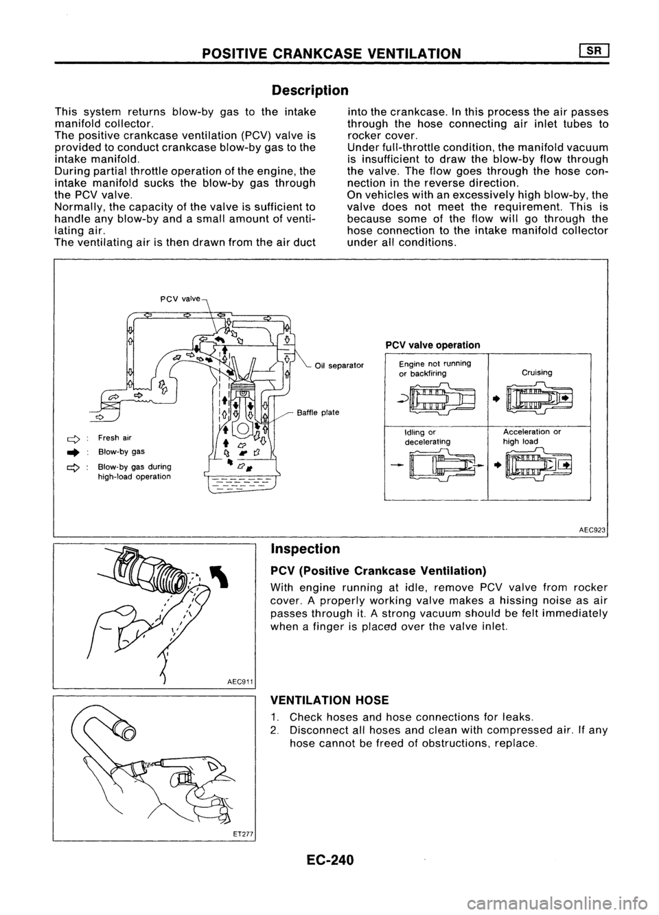
Description
This system returnsblow-by gastothe intake
manifold collector.
The positive crankcase ventilation (PCV)valveis
provided toconduct crankcase blow-bygastothe
intake manifold.
During partialthrottle operation ofthe engine, the
intake manifold suckstheblow-by gasthrough
the
pev
valve.
Normally, thecapacity ofthe valve issufficient to
handle anyblow-by andasmall amount ofventi-
lating air.
The ventilating airisthen drawn fromtheairduct into
thecrankcase. Inthis process theairpasses
through thehose connecting airinlet tubes to
rocker cover.
Under full-throttle condition,themanifold vacuum
is insufficient todraw theblow-by flowthrough
the valve. Theflow goes through thehose con-
nection inthe reverse direction.
On vehicles withanexcessively highblow-by, the
valve doesnotmeet therequirement. Thisis
because someofthe flow willgothrough the
hose connection tothe intake manifold collector
under allconditions.
Oil separator
q
Freshair
.. Blow-by gas
ct>
Blow-by gasduring
high-load operation Baffle
plate
PCV
valve operation
Engine notrunning
or backfiring Cruising
~~
.0
Idling or Acceleration
or
decelerating high
load
-~--
.~
AEC923
Inspection
PCV (Positive Crankcase Ventilation)
With engine running atidle, remove PCVvalve fromrocker
cover. Aproperly workingvalvemakes ahissing noiseasair
passes through it.Astrong vacuum shouldbefelt immediately
when afinger isplaced overthevalve inlet.
AEC911 VENTILATION HOSE
1. Check hosesandhose connections forleaks.
2. Disconnect allhoses andclean withcompressed air.Ifany
hose cannot befreed ofobstructions, replace.
ET277 EC-240
Page 962 of 1701

BASICSERVICE PROCEDURE
Idle Speedllgnition TiminglldleMixtureRatio
Adjustment
PREPARATION
• Make surethatthefollowing partsarein
good order.
(1) Battery
(2) Ignition system
(3) Engine oiland coolant levels
(4) Fuses
(5) ECM harness connector
(6) Vacuum hoses
(7) Airintake system
(Oil filler cap,oillevel gauge, etc.)
(8) Fuel pressure
(9) Engine compression
(10) Throttle valve
Overall inspection sequence
INSPECTION
•
•
•
•
•
•
On
models equipped withairconditioner,
checks shouldbecarried outwhile theair
conditioner is"OFF".
On models equipped withautomatic
transaxle, whenchecking idlespeed, ignition
timing andmixture ratio,checks shouldbe
carried outwhile shiftlever isin "N" position.
When measuring "CO"percentage, insert
probe morethan40cm (15.7 in)into tailpipe.
Turn offheadlamps, heaterblower, rear
defogger. Keep frontwheels pointed straight ahead.
Make thecheck afterthecooling fanhas
stopped.
•
Perform diagnostic testmode II
(Self-diagnostic results).
OK
Check
&
adjust ignition timing.
Check
&
adjust idlespeed.
Check heated oxygen sensor
function. NG
Repair orreplace.
NG Check heated oxygen sensor
harness. NG
Repair orreplace harness.
OK OK
Check CO%. OKReplace heatedoxygen sensor.
NG
INSPECTION END Check
emission controlparts
and repair orreplace ifneces-
sary.
EC-243
NG
Check heated oxygen sensor
function.
OK
Page 963 of 1701
@
START
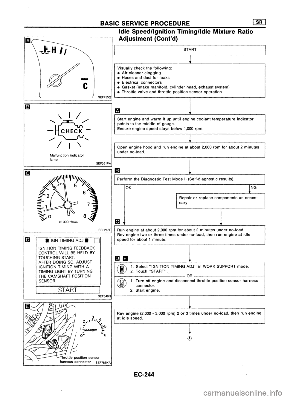
Visually checkthefollowing:
• Air cleaner clogging
• Hoses andduct forleaks
• Electrical connectors
• Gasket (intakemanifold, cylinderhead,exhaust system)
• Throttle valveandthrottle position sensoroperation
m
Start engine andwarm itup until engine coolant temperature indicator
points tothe middle ofgauge.
Ensure enginespeedstaysbelow 1,000rpm.
1
Open engine hoodandrunengine atabout 2,000rpmforabout 2minutes
under no-load.
Ii]
Perform theDiagnostic TestMode
1\
(Self-diagnostic results).
OK ~NG
Repair orreplace components asneces-
sary.
[!J
Run engine atabout 2,000rpmforabout 2minutes underno-load.
Rev engine twoorthree times under no-load, thenrunengine atidle
speed forabout 1minute .
li]1!I
00
1.
Select "IGNITION TIMINGADJ"inWORK SUPPORT mode.
2. Touch "START" .
.
OR
00
1.
Turn offengine anddisconnect throttleposition sensorharness
connector.
2. Start engine.
Rev engine (2,000-3,000 rpm)2or 3times under no-load, thenrunengine
at idle speed.
t
Throttle position sensor
harness connector SEF785KASEF051PA
BASIC
SERVICE PROCEDURE Em
Idle Speedllgnition TiminglldleMixtureRatio
Adjustment (Cont'd)
SEF248F
SEF455Q
Malfunction indicator
lamp \
I/
'~,,/
- CHECK-
,,/
........
/ I\
Ii] •IGN TIMING ADJ.
D
IGNITION TIMINGFEEDBACK
CONTROL WILLBEHELD BY
TOUCHING START.
AFTER DOING SO,ADJUST
IGNITION TIMINGWITHA
TIMING LIGHTBYTURNING
THE CAMSHAFT POSITION
SENSOR.
I
START
I
SEF546N
EC-244
Page 974 of 1701
ON-BOARDDIAGNOSTIC SYSTEMDESCRIPTION
CONSULT (Coni'd)
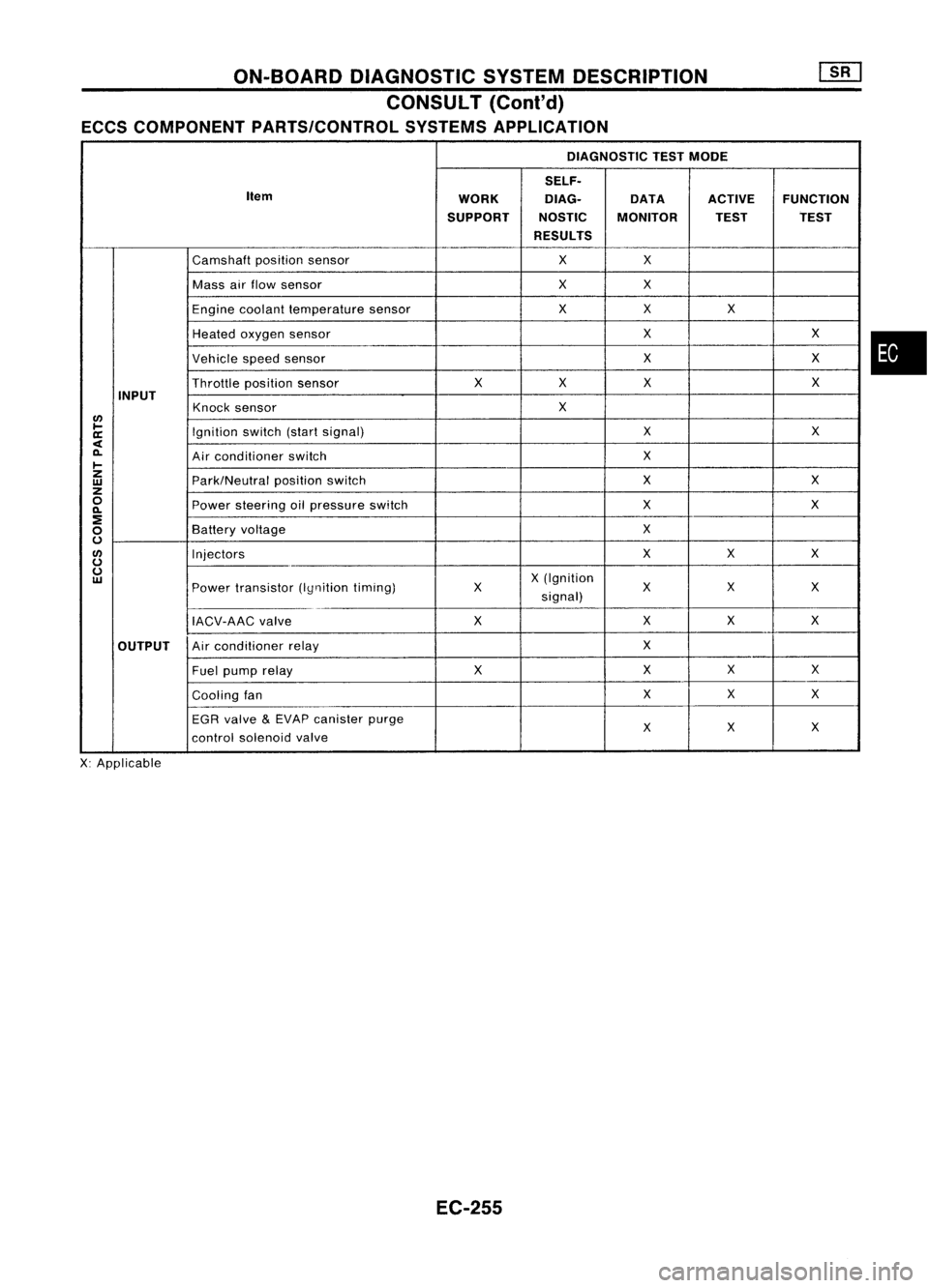
ECCS COMPONENT PARTS/CONTROL SYSTEMSAPPLICATION
DIAGNOSTIC TESTMODE
SELF.
Item WORKDlAG.
DATAACTIVEFUNCTION
SUPPORT NOSTICMONITOR TESTTEST
RESULTS
Camshaft positionsensor XX
Mass airflow sensor XX
Engine coolant temperature sensor XX
X
Heated oxygen sensor X
X
Vehicle speedsensor X
X
Throttle positionsensor X
XX X
INPUT Knocksensor X
lJ)
~ Ignitionswitch(startsignal) X
X
a:
<
0-
Airconditioner switch X
~
z
Park/Neutralpositionswitch X
X
w
z
0
Powersteering oilpressure switch X
X
0-
:!
X
0
Battery
voltage
0
lJ)
Injectors XX
X
0
0
X(Ignition
w
Powertransistor (Iynitiontiming) X
XX
X
signal)
IACV-AAC valve XX
XX
OUTPUT Air
conditioner relay X
Fuel pump relay XXX
X
Cooling fan X
X
X
EGR valve
&
EVAP canister purge
X
X
X
control solenoid valve
X: Applicable
EC-255
•
Page 975 of 1701
ON-BOARDDIAGNOSTIC SYSTEMDESCRIPTION
CONSULT (Cont'd)
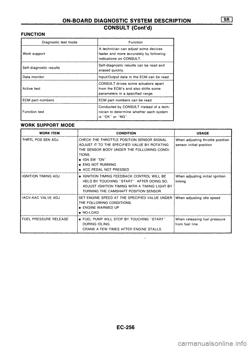
FUNCTION
Diagnostictestmode Function
A technician canadjust somedevices
Work support
fasterandmore accurately byfollowing
indications onCONSULT.
Self-diagnostic results Self-diagnostic
resultscanberead and
erased quickly.
Data monitor
Input/Outputdatainthe ECM canberead.
CONSULT drivessomeactuators apart
Active test fromtheECM's andalso shifts some
parameters inaspecified range.
ECM partnumbers
ECMpartnumbers canberead.
Conducted byCONSULT insteadofatech-
Function test
niciantodetermine whethereachsystem
is "OK" or"NG".
WORK SUPPORT MODE
WORK ITEM
CONDITION USAGE
THRTL POSSENADJ
CHECKTHETHROTTLE POSITIONSENSORSIGNAL. Whenadjusting throttleposition
ADJUST ITTO THE SPECIFIED VALUEBYROTATING
sensorinitialposition
THE SENSOR BODYUNDER THEFOLLOWING CONDI-
TIONS .
• IGN SW"ON"
• ENG NOTRUNNING
• ACC PEDAL NOTPRESSED
IGNITION TIMINGADJ
•IGNITION TIMINGFEEDBACK CONTROLWILLBE
Whenadjusting initialignition
HELD BYTOUCHING "START".AFTERDOINGSO, timing
ADJUST IGNITION TIMINGWITHATIMING LIGHTBY
TURNING THECAMSHAFT POSITIONSENSOR.
IACV-AAC VALVEADJ
SETENGINE SPEEDATTHE SPECIFIED VALUEUNDER
Whenadjusting idlespeed
THE FOLLOWING CONDITIONS.
• ENGINE WARMED UP
• NO-LOAD
FUEL PRESSURE RELEASE •FUEL PUMP WILLSTOP BYTOUCHING "START"
Whenreleasing fuelpressure
DURING IDLING.
fromfuelline
CRANK AFEW TIMES AFTER ENGINE STALLS
EC-256
Page 979 of 1701
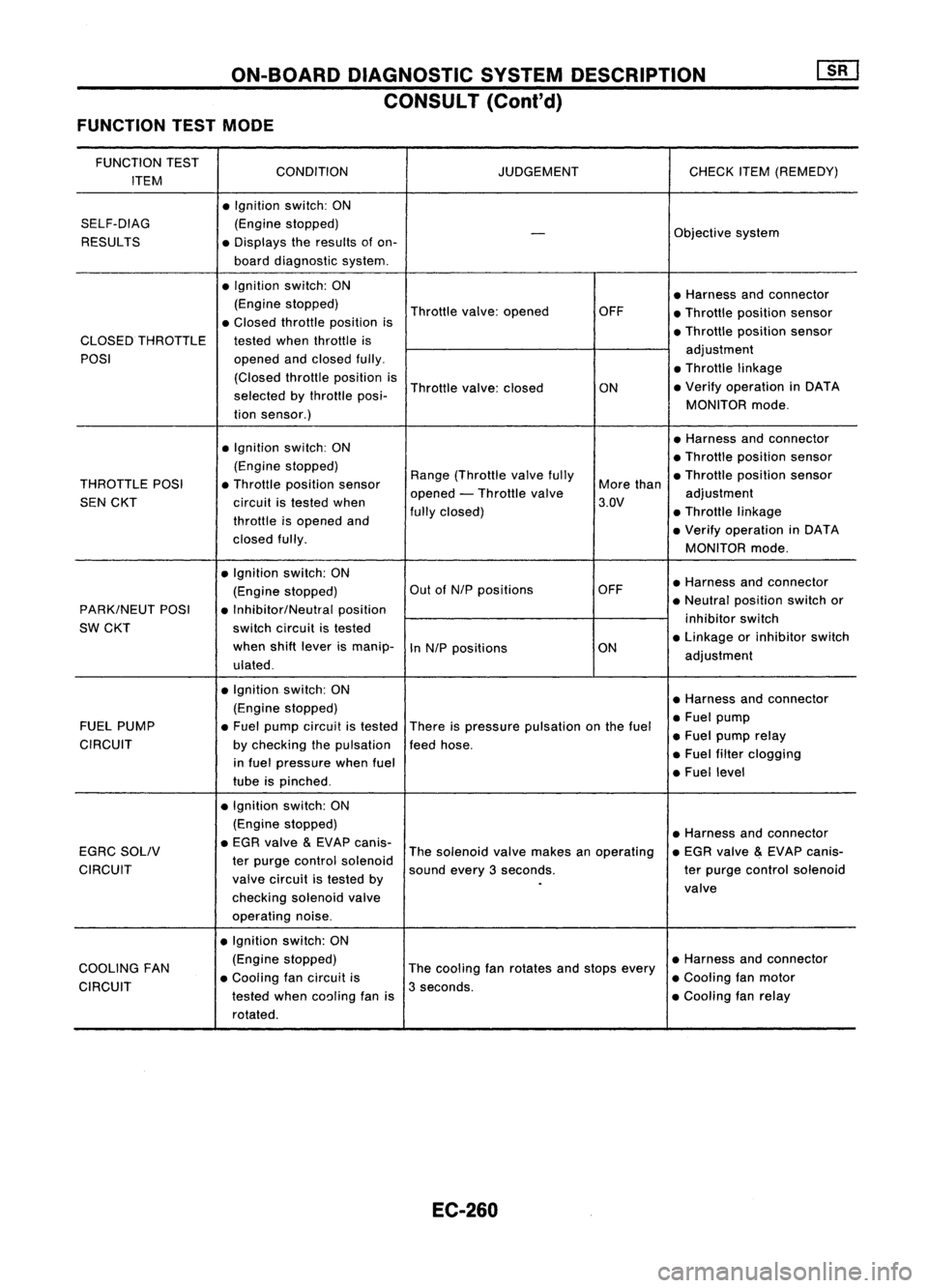
ON-BOARDDIAGNOSTIC SYSTEMDESCRIPTION
CONSULT (Conl'd)
FUNCTION TESTMODE
FUNCTION TEST
CONDITION JUDGEMENTCHECKITEM(REMEDY)
ITEM
•Ignition switch:ON
SELF-DIAG (Enginestopped)
Objectivesystem
-
RESULTS •Displays theresults ofon-
board diagnostic system.
• Ignition switch:ON
•Harness andconnector
(Engine stopped)
Throttlevalve:opened OFF
•Throttle position sensor
• Closed throttle position is
•Throttle position sensor
CLOSED THROTTLE testedwhenthrottle is
POSI opened
andclosed fully. adjustment
• Throttle linkage
(Closed throttleposition is
Throttle valve:closed
ON•
Verify operation inDATA
selected bythrottle posi-
MONITORmode.
tion sensor.)
• Ignition switch:ON •
Harness andconnector
• Throttle position sensor
(Engine stopped)
Range(Throttle valvefully •Throttle position sensor
THROTTLE POSI•Throttle position sensor
opened-Throttle valve More
than
adjustment
SEN CKT circuitistested when 3.QV
throttle isopened and fully
closed) •Throttle linkage
• Verify operation inDATA
closed fully.
MONITORmode.
• Ignition switch:ON
•Harness andconnector
(Engine stopped) Out
ofN/P positions OFF
PARK/NEUT POSI•Inhibitor/Neutral position •
Neutral position switchor
SW CKT switch
circuit istested inhibitor
switch
when shiftlever ismanip-
InN/P positions ON•
Linkage orinhibitor switch
ulated . adjustment
• Ignition. switch:ON
•Harness andconnector
(Engine stopped)
•Fuel pump
FUEL PUMP •Fuel pump circuit istested
Thereispressure pulsation onthe fuel
•Fuel pump relay
CIRCUIT bychecking thepulsation feedhose.
in fuel pressure whenfuel •
Fuel filter clogging
tube ispinched . •
Fuel level
• Ignition switch:ON
(Engine stopped)
•Harness andconnector
EGRC SOLIV •
EGR valve
&
EVAP canis-
Thesolenoid valvemakes anoperating •
EGR valve
&
EVAP canis-
CIRCUIT ter
purge control solenoid
soundevery3seconds. terpurge control solenoid
valve circuit istested by
.
valve
checking solenoidvalve
operating noise.
• Ignition switch:ON
COOLING FAN (Engine
stopped)
Thecooling fanrotates andstops every •
Harness andconnector
• Cooling fancircuit is •Cooling fanmotor
CIRCUIT testedwhencoaling fanis3
seconds.
•Cooling fanrelay
rotated.
EC-260
Page 989 of 1701
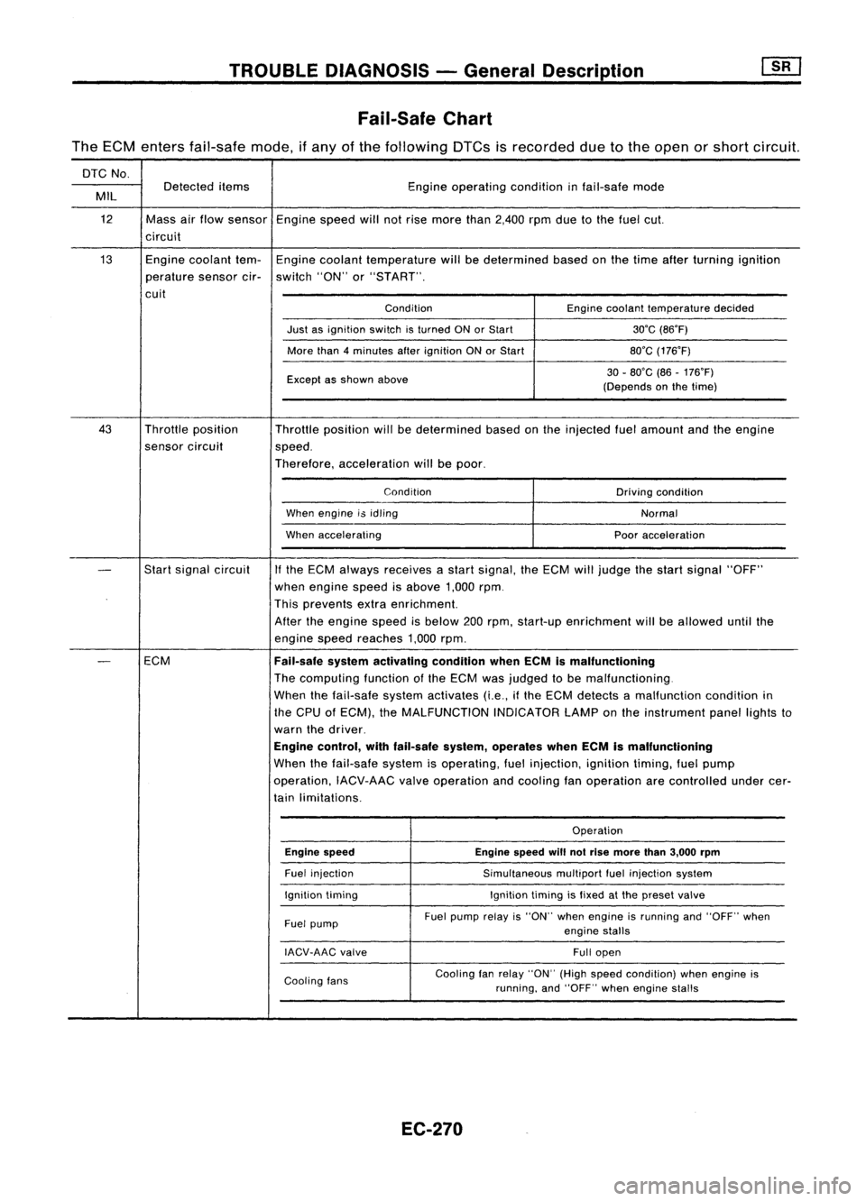
TROUBLEDIAGNOSIS -General Description
Fail-Safe Chart
The ECM enters fail-safe mode,ifany ofthe following DTCsisrecorded duetothe open orshort circuit.
DTC No.
Detected items Engineoperating conditioninfail-safe mode
MIL
12 Massairflow sensor Enginespeedwillnotrise more than2,400 rpmduetothe fuel cut.
circuit
13 Enginecoolant tem-Engine coolant temperature willbedetermined basedonthe time after turning ignition
perature sensorcir-switch "ON"or"START".
cuit ConditionEnginecoolant temperature decided
Just asignition switchisturned ONorStart 30'C(86'F)
More than4minutes afterignition ONorStart 80'C(176'F)
Except asshown above 30
-80'C (86-176'F)
(Depends onthe time)
43 Throttle position
Throttleposition willbedetermined basedonthe injected fuelamount andtheengine
sensor circuit
speed.
Therefore, acceleration willbepoor.
Condition Drivingcondition
When engine i$idling
Normal
When accelerating Pooracceleration
-
Start
signal circuit
If
the ECM always receives astart signal, theECM willjudge thestart signal "OFF"
when engine speedisabove 1,000rpm.
This prevents extraenrichment.
After theengine speedisbelow 200rpm, start-up enrichment willbeallowed untilthe
engine speedreaches 1,000rpm.
-
ECM
Fail-safesystemactivating conditionwhenECMismalfunctioning
The computing functionofthe ECM wasjudged tobe malfunctioning.
When thefail-safe systemactivates (i.e.,ifthe ECM detects amalfunction conditionin
the CPU ofECM), theMALFUNCTION INDICATORLAMPonthe instrument panellightsto
warn thedriver.
Engine control, withfail-safe system,operates whenECMismalfunctioning
When thefail-safe systemisoperating, fuelinjection, ignitiontiming,fuelpump
operation, IACV-AACvalveoperation andcooling fanoperation arecontrolled undercer-
tain limitations.
Operation
Engine speed Enginespeedwillnotrise more than3,000 rpm
Fuel injection
Simultaneousmultiportfuelinjection system
Ignition timing Ignitiontimingisfixed atthe preset valve
Fuel pump Fuel
pump relayis"ON" whenengine isrunning and"OFF" when
engine stalls
IACV-AAC valve
Fullopen
Cooling fans Cooling
fanrelay "ON" (Highspeed condition) whenengine is
running, and"OFF" whenengine stalls
EC-270
Page 991 of 1701
![NISSAN ALMERA N15 1995 Service Manual
I!]
CHECK IDLEADJ. SCREW INITIALSET
NG
Adjust engine speedby
---..
RPM.
turningidleadjusting
00
1.
Select "IGNTIMING ADJ"in screw.
"WORK SUPPORT" mode.
2. When touching "STAR NISSAN ALMERA N15 1995 Service Manual
I!]
CHECK IDLEADJ. SCREW INITIALSET
NG
Adjust engine speedby
---..
RPM.
turningidleadjusting
00
1.
Select "IGNTIMING ADJ"in screw.
"WORK SUPPORT" mode.
2. When touching "STAR](/manual-img/5/57349/w960_57349-990.png)
I!]
CHECK IDLEADJ. SCREW INITIALSET
NG
Adjust engine speedby
---..
RPM.
turningidleadjusting
00
1.
Select "IGNTIMING ADJ"in screw.
"WORK SUPPORT" mode.
2. When touching "START",
does engine speedfallto
750:!: 50rpm
(AfT
in
"N"
posi-
tion)?
OR
00
Does
engine runat750:!: 50rpm
(AfT
In
"N"
position)?
OK
Reconnect throttleposition sensorhar-
ness connector.
Ii
CHECK THROTTLE POSITIONSENSOR
NG
Adjust outputvoltage to
IDLE POSITION.
---..
0.50Vbyrotating throttle
00
1.
Perform ''THRTLPOSSEN
positionsensorbody.
ADJ" in"WORK SUPPORT"
1
mode.
2. Check thatoutput voltage of
RESETIDLEPOSITION
throttle position sensoris
MEMORY.
approx. 0.35to0.65V (Throttle
1.Warm upengine suffi-
valve fullycloses.) and"CLSD ciently.
2. Turn ignition switch
THLIPOSI" stays"ON".
"OFF"andwait at
OR least5seconds.
00
Measure
outputvoltage ofthrot- 3.
Disconnect throttle
position sensorhar-
tie position sensorusing
nessconnector.
voltmeter, andcheck thatitis
4.
Start engine andwait
approx. 0.35toO.65V. (Throttle at
least 5seconds in
"N" position.
valve fullyclosed.)
5.Reconnect throttle
OK • position
sensorhar-
ness connector while
running engine.
~
1
,
THRTL
POSSEN O,52V
SEF165P
•••
ADJMONITOR •••
TROUBLE
DIAGNOSIS -General Description
Basic Inspection (Cont'd)
@
========
MONITOR
========
CMPS.RPM (REF)Orpm
CLSDTHUP ON
Ii
•
THRTL POSSENADJ
.0
I!]
•IGN TIMING ADJ.
0
IGNITION TIMINGFEEDBACK
CONTROL WILLBEHELD BY
TOUCHING START
AFTER DOING SO,ADJUST
IGNITION TIMINGWITHA
TIMING LIGHTBYTURNING
THE CAMSHAFT POSITION
SENSOR
I
START
I
SEF546N
CID
(Go tonext page)
EC-272