1995 NISSAN ALMERA N15 Throttle valve
[x] Cancel search: Throttle valvePage 756 of 1701
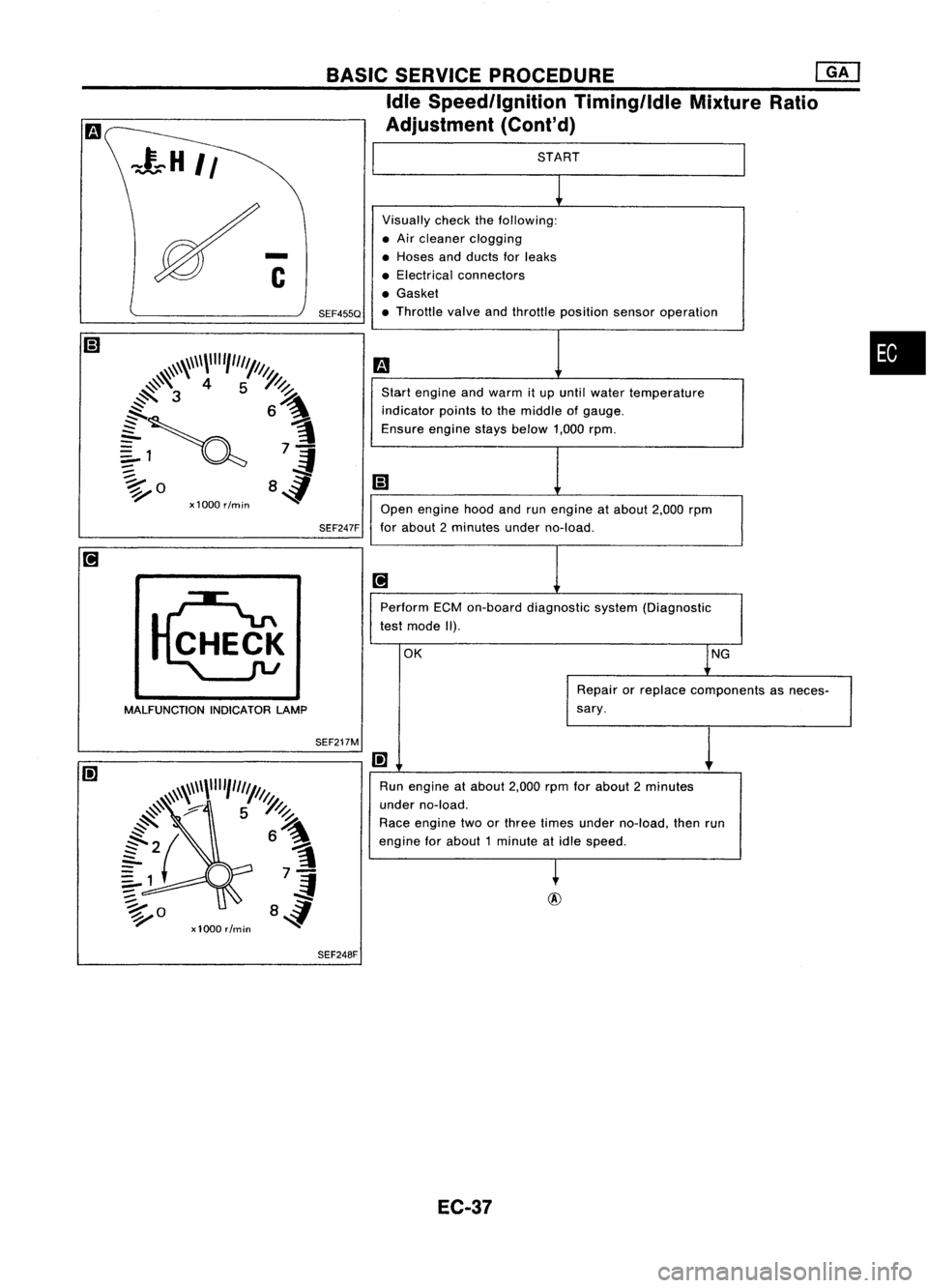
SEF217M
•
START
Visually checkthefollowing:
• Air cleaner clogging
• Hoses andducts forleaks
• Electrical connectors
• Gasket
• Throttle valveandthrottle position sensoroperation
m
Start engine andwarm itup until water temperature
indicator pointstothe middle ofgauge.
Ensure enginestaysbelow 1,000rpm.
iii
Open engine hoodandrunengine atabout 2,000rpm
for about 2minutes underno-load.
[iJ
Perform ECMon-board diagnostic system(Diagnostic
test mode II).
OK lNG
Repair orreplace components asneces-
sary.
I!]
1
Run engine atabout 2,000rpmforabout 2minutes
under no-load.
Race engine twoorthree times under no-load, thenrun
engine forabout 1minute atidle speed.
~
BASIC
SERVICE PROCEDURE
eM]
Idle Speed/Ignition Timing/IdleMixtureRatio
Adjustment (Cont'd)
SEF247F
SEF455Q
MALFUNCTION INDICATORLAMP
SEF248F
EC-37
Page 768 of 1701
ON-BOARDDIAGNOSTIC SYSTEMDESCRIPTION
CONSULT (Cont'd)
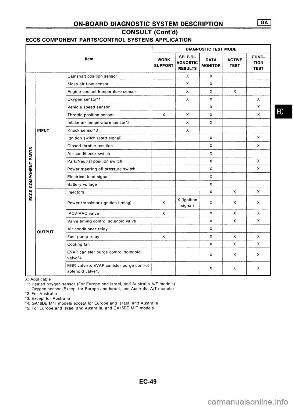
ECCS COMPONENT PARTS/CONTROL SYSTEMSAPPLICATION
DIAGNOSTICTESTMODE
Item WORKSELF-DI-
ACTIVEFUNC-
DATA
SUPPORT AGNOSTIC
MONITOR TION
TEST
RESULTS TEST
Camshaft positionsensor
X
X
Mass airflow sensor
X
X
Engine coolant temperature sensor
X
X X
Oxygen sensor'1
X
X X
Vehicle speedsensor
XX
Throttle positionsensor
XX
X X
Intake airtemperature sensor.'2
X
X
INPUT
Knock
sensor'3
X
Ignition switch(startsignal)
XX
I/)
Closed
throttle position
X
X
l-
ll:
Airconditioner switch
X
<
~
Park/Neutralpositionswitch
X
X
I-
Z
UJ
Powersteering oilpressure switch
XX
z
0
Electricalloadsignal
X
~
:E
0
Batteryvoltage
X
u
I/)
Injectors
XX
X
u
u
UJ
X(Ignition
Power transistor (Ignitiontiming) X X
XX
signal)
IACV-AAC valve X
XX
X
Valve timing control solenoid valve XX
X
OUTPUT
Air
conditioner relay
X
Fuel pump relay XX
XX
Cooling fan XX
X
EVAP canister purgecontrol solenoid
XX X
valve'4
EGR valve
&
EVAP canister purgecontrol
XX
X
solenoid valve'5
X: Applicable
'1: Heated oxygen sensor(ForEurope andIsrael, andAustralia AITmodels)
Oxygen sensor(Except forEurope andIsrael, andAustralia AITmodels)
'2: For Australia
'3: Except forAustralia
'4: GA16DE
MIT
models exceptforEurope andIsrael, andAustralia
'5: For Europe andIsrael andAustralia, andGA15DE
MIT
models
EC-49
•
Page 769 of 1701
ON-BOARDDIAGNOSTIC SYSTEMDESCRIPTION
CONSULT (Cont'd)
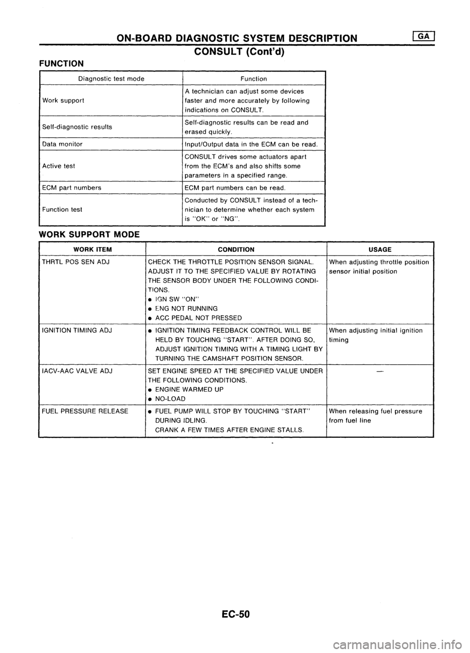
FUNCTION
Diagnostictestmode
Function
A technician canadjust somedevices
Work support
fasterandmore accurately byfollowing
indications onCONSULT.
Self-diagnostic results Self-diagnostic
resultscanberead and
erased quickly.
Data monitor
Input/Outputdatainthe ECM canberead.
CONSUL Tdrives someactuators apart
Active test
fromtheECM's andalso shifts some
parameters inaspecified range.
ECM partnumbers ECMpartnumbers canberead.
Conducted byCONSULT insteadofatech-
Function test
niciantodetermine whethereachsystem
is "OK" or"NG".
WORK SUPPORT MODE
WORK ITEM
CONDITION USAGE
THRTL POSSENADJ
CHECKTHETHROTTLE POSITIONSENSORSIGNAL. Whenadjusting throttleposition
ADJUST iTTO THE SPECIFIED VALUEBYROTATING
sensorinitialposition
THE SENSOR BODYUNDER THEFOLLOWiNG CONDI-
TIONS .
• IGN SW"ON"
• ENG NOTRUNNING
• ACC PEDAL NOTPRESSED
IGNITION TIMINGADJ
•IGNITION TIMINGFEEDBACK CONTROLWILLBE Whenadjusting initialignition
HELD BYTOUCHING "START".AFTERDOINGSO,
timing
ADJUST IGNITION TIMINGWITHATIMING LIGHTBY
TURNING THECAMSHAFT POSITIONSENSOR.
IACV-AAC VALVEADJ SETENGINE SPEEDATTHE SPECIFIED VALUEUNDER
-
THE FOllOWING CONDITIONS.
• ENGINE WARMED UP
• NO-LOAD
FUEL PRESSURE RELEASE •FUEL PUMP WillSTOP BYTOUCHING "START" Whenreleasing fuelpressure
DURING IDLING. fromfuelline
CRANK AFEW TIMES AFTER ENGINE STALLS.
EC-50
Page 773 of 1701
ON-BOARDDIAGNOSTIC SYSTEMDESCRIPTION
CONSULT (Cont'd)
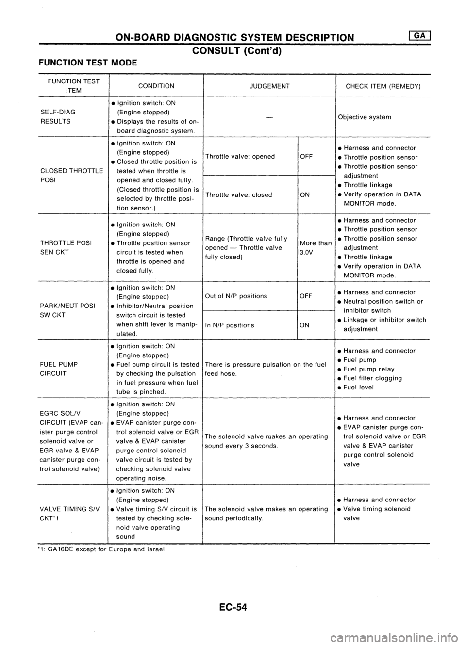
FUNCTION TESTMODE
FUNCTION TEST
CONDITION
ITEM JUDGEMENT
CHECKITEM(REMEDY)
• Ignition switch:ON
SELF-DIAG (Enginestopped)
RESULTS
-
Objective
system
• Displays theresults ofon-
board diagnostic system.
• Ignition switch:ON
•Harness andconnector
(Engine stopped)
Throttlevalve:opened OFF
•Throllle position sensor
• Closed throllle position is
•Throllie position sensor
CLOSED THROTTLE
testedwhenthrottle is
POSI openedandclosed fully. adjustment
(Closed throllieposition is •
Throttle linkage
selected bythrottle posi- Throttle
valve:closed
ON•
Verify operation inDATA
tion sensor.) MONITOR
mode.
• Ignition switch:ON •
Harness andconnector
(Engine stopped) •
Throttle position sensor
THROTTLE POSI•Throllle position sensor Range
(Throllle valvefully
Morethan •
Throllle position sensor
SEN CKT
circuitistested when opened
-Throllle valve
3.DV adjustment
throllie isopened and fully
closed) •Throllie linkage
closed fully. •
Verify operation inDATA
MONITOR mode.
• Ignition switch:ON
•Harness andconnector
(Engine stopoed) Out
ofNIP positions OFF
PARK/NEUT POSI
•Inhibitor/NelJlral position •
Neutral position switchor
SW CKT switchcircuit istested inhibitor
switch
when shiftlever ismanip-
InNIP positions ON•
Linkage orinhibitor switch
ulated . adjustment
• Ignition switch:ON
•Harness andconnector
(Engine stopped)
•Fuel pump
FUEL PUMP •Fuel pump circuit istested
Thereispressure pulsation onthe fuel
•Fuel pump relay
CIRCUIT bychecking thepulsation feedhose.
in fuel pressure whenfuel •
Fuel filter clogging
tube ispinched . •
Fuel level
• Ignition switch:ON
EGRC SOllV (Engine
stopped)
•Harness andconnector
CIRCUIT (EVAPcan-•EVAP canister purgecon-
•EVAP canister purgecon-
ister purge control trolsolenoid valveorEGR
Thesolenoid valvemakes anoperating trolsolenoid valveorEGR
solenoid valveor
valve
&
EVAP canister
soundevery3seconds. valve
&
EVAP canister
EGR valve
&
EVAP purgecontrol solenoid
purgecontrol solenoid
canister purgecon- valvecircuit istested by
valve
trol solenoid valve) checkingsolenoidvalve
operating noise.
• Ignition switch:ON
(Engine stopped) •
Harness andconnector
VALVE TIMING SIV•Valve timing SIVcircuit isThe
solenoid valvemakes anoperating •
Valve timing solenoid
CKT*1 testedbychecking sole-soundperiodically. valve
noid valve operating
sound
'1: GA16DE exceptforEurope andIsrael
EC-54
Page 783 of 1701
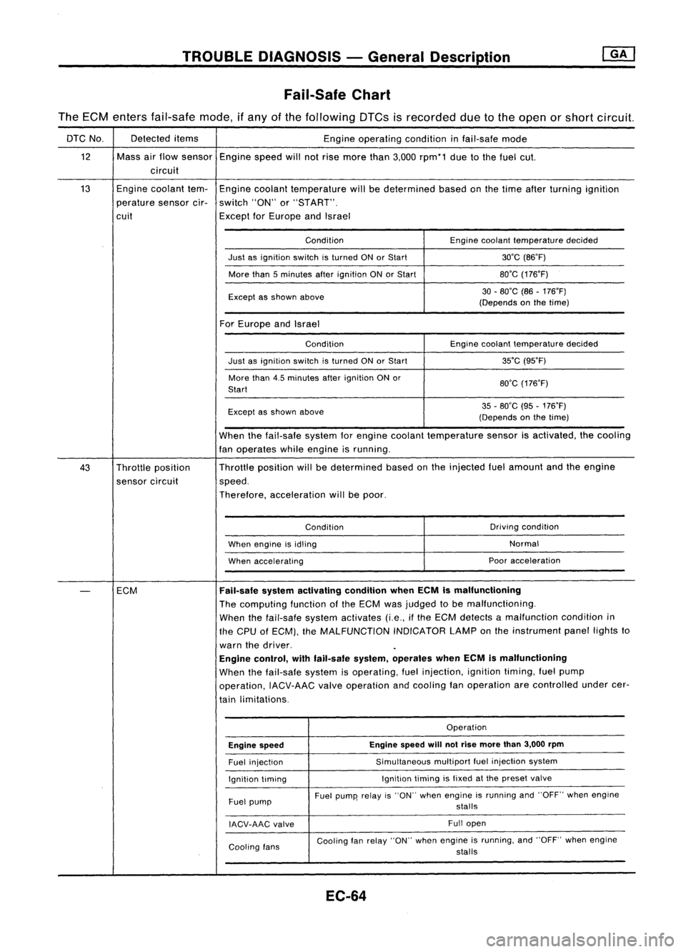
TROUBLEDIAGNOSIS -General Description
Fail-Safe Chart
The ECM enters fail-safe mode,ifany ofthe following DTCsisrecorded duetothe open orshort circuit.
DTC No. Detected
items
Engineoperating conditioninfail-safe mode
12 Massairflow sensor
Enginespeedwillnotrise more than3,000 rpm*1 duetothe fuel cut.
circuit
13 Engine
coolant tem-
Engine coolant temperature willbedetermined basedonthe time after turning ignition
perature sensorcir-switch "ON"or"START".
cuit ExceptforEurope andIsrael
Condition Enginecoolant temperature decided
Just asignition switchisturned ONorStart 30'C(B6'F)
More than5minutes afterignition ONorStart BO'G
(176'F)
Except asshown above 30
-BO'C (B6-176'F)
(Depends onthe time)
For Europe andIsrael
Condition Enginecoolant temperature decided
Just asignition switchisturned ONorStart 35'C
(95'F)
More than4.5minutes afterignition ONor
BO'G(176'F)
Start
Except asshown above 35
-BO'C (95-176'F)
(Depends onthe time)
When thefail-safe systemforengine coolant temperature sensorisactivated, thecooling
fan operates whileengine isrunning.
43 Throttle position Throttle
position willbedetermined basedonthe injected fuelamount andtheengine
sensor circuit speed.
Therefore, acceleration willbepoor.
Condition Driving
condition
When engine isidling Normal
When accelerating Poor
acceleration
-
ECM
Fail-safe
systemactivating conditionwhenECMismalfunctioning
The computing functionofthe ECM wasjudged tobe malfunctioning.
When thefail-safe systemactivates (i.e.,ifthe ECM detects amalfunction conditionin
the CPU ofECM), theMALFUNCTION INDICATORLAMPonthe instrument panellightsto
warn thedriver.
Engine control, withfail-safe system,operates whenECMismalfunctioning
When thefail-safe systemisoperating, fuelinjection, ignitiontiming,fuelpump
operation, IACV-AACvalveoperation andcooling fanoperation arecontrolled undercer-
tain limitations.
Operation
Engine speed Engine
speed
will
notrise more than3,000 rpm
Fuel injection Simultaneous
multipartfuelinjection system
Ignition timing Ignition
timingisfixed atthe preset valve
Fuel pump Fuel
pump' relayis"ON" when engine isrunning and"OFF" whenengine
stalls
IACV-AAG valve Full
open
Cooling fans Cooling
fanrelay "ON" whenengine isrunning, and"OFF" whenengine
stalls
EC-64
Page 785 of 1701
![NISSAN ALMERA N15 1995 Service Manual @
(Go tonext page)
(;]
1
CHECK IDLEADJ. SCREW INITIALSET
NG
Adjust engine speedby
~
RPM.
turning
idleadjusting
Base idlespeed: RefertoEC-36.
screw.
II
t
K
CHECK THROTTLE POSITIONSENSOR
NG
NISSAN ALMERA N15 1995 Service Manual @
(Go tonext page)
(;]
1
CHECK IDLEADJ. SCREW INITIALSET
NG
Adjust engine speedby
~
RPM.
turning
idleadjusting
Base idlespeed: RefertoEC-36.
screw.
II
t
K
CHECK THROTTLE POSITIONSENSOR
NG](/manual-img/5/57349/w960_57349-784.png)
@
(Go tonext page)
(;]
1
CHECK IDLEADJ. SCREW INITIALSET
NG
Adjust engine speedby
~
RPM.
turning
idleadjusting
Base idlespeed: RefertoEC-36.
screw.
II
t
K
CHECK THROTTLE POSITIONSENSOR
NG
Adjust output
voltage
to
~
IDLE POSITION.
0.50
:l:
0.1V byrotating
00
1.
Perform ''THRTlPOSSEN throttle
position sensor
ADJ" in"WORK SUPPORT" body.
mode.
2. Check thatoutput
voltage
of
throttle position sensoris
approx. 0.35to0.65V (Throttle
valve
fullycloses.) and"ClSD
THlIP SW"stays "ON".
OR
00
Measure
output
voltage
ofthrot-
tle position sensorusing
voltmeter,
andcheck thatitis
approx. 0.35to0.65V. (Throttle
valve
fullyclosed.)
OK
RESETIDLEPOSITION
MEMORY.
1. Warm upengine suffi-
ciently.
2. Turn ignition switch
"OFF" andwait at
least 5seconds.
3. Disconnect
throttle
position sensorhar-
ness connector.
4.
Start
engine andwait
at least 5seconds in
"N" position .
5. Reconnect throttle
position sensorhar-
ness connector while
running engine.
TROUBLE
DIAGNOSIS -General Description
Basic Inspection (Coni'd)
@
• THRTl POSSEN ADJ.
0
* **
ADJ MONITOR
***
THRTL POSSEN 0.52V
==========
MONITOR
==========
CMPS.RPM (REF)Orpm
CLSD THLIPOSI ON
SEF516Q
SEF12BR EC-66
Page 792 of 1701
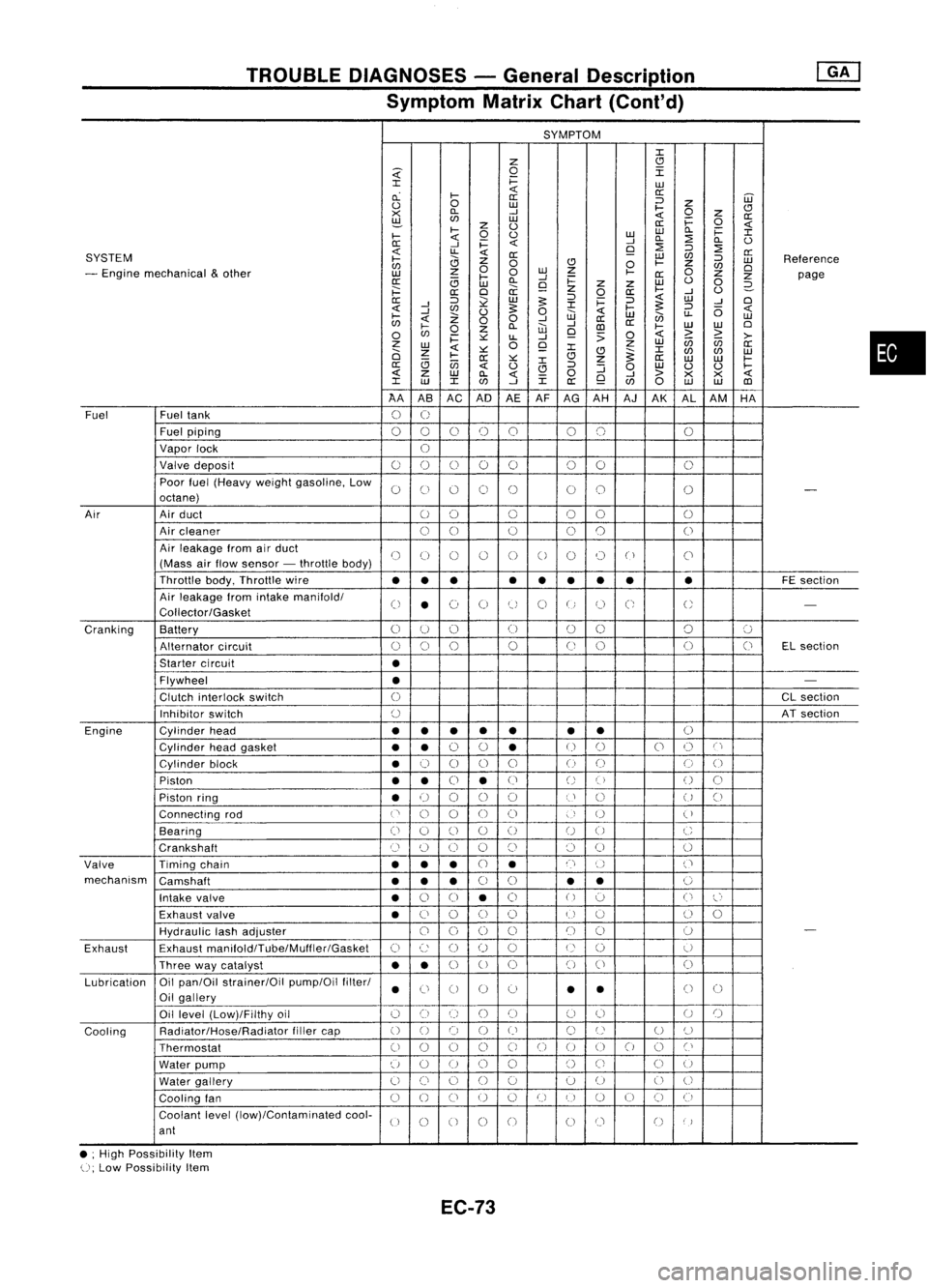
TROUBLEDIAGNOSES -General Description
Symptom MatrixChart(Cont'd)
SYMPTOM
J:
Z
CJ
~
0
I
J:
i=
LU
cL
I-
«
a:
a: ::J
UJ
0
0
LU
I-
Z
CJ
><
D..
-'
«
0
z
a:
~
LU
i=
0
z
0
a:
«
I-
0
0
LULU
D..
i=
J:
I-
«
-'
D..
:2
D..
0
0:
-'
i=
«
9
:2
::J
:2
SYSTEM
«
LL
«
0:
LU
C/J
a:
I-
0
Z
0
CJ
0
I-
Z
::J
LU
Reference
C/J
0
C/J
0
- Engine mechanical
&
other
z
0
LU
Z
I-
0
LU
I-
-'
0:
Z
Z
page
0:
(3
LU
D..
9
i=
z
Z
LU
0
0
2-
;:::
a:
0
a:
z
0
a:
I-
-'
0
0:
::J
~
LU
5:
::J
i=
::J
«
LU
-'
0
-'
J:
5:
«
-'
C/J
0
5:
0
«
I-
::J
(5
«
I-
Z
W
LU
en
LL
LU
C/J
«
00
-'
-'
a:
a:
0
I-
0
Z
D..
W
CD
I-
LU
LU
0
C/J
i=
~
LL
-'
9
:>
0
«
>
~
>-
z
0
Z
LU
(ij
C/J
a:
LU
«
~
9
J:
J:
0
Z
CJ
~
C/J
C/J
LU
I-
0:
~
CJ
Z
a:
LU LU
I-
(3
(jj
J:
a:
«
0
CJ
::J
:J
0
LU
0 0
I-
«
z
LU
D..
«
0
-'
>
><><
«
J:
LU
J:
C/J
-'
J:
a:
9
C/J
0
LU LU
CD
AA ASAC AD
AEAF
AG AH AJAK ALAM HA
Fuel Fueltank
0
U
Fuel piping
00 0
()
0 00 0
Vapor lock
U
Valve deposit
00 000 00
0
Poor fuel(Heavy weightgasoline, Low
0
C)
0 0
()
00
0
-
octane)
Air Airduct
00 0
00
0
Air cleaner
00
0
0
0
0
Air leakage fromairduct
()
(J
()
()
0
0
0 0
("
)
C'
(Mass airflow sensor -throttle body)
Throttle body,Throttle wire
••• •
••
•• •
FE
section
Air leakage fromintake manifold/
0
•
(~)
0
tJ
0
U
C;
U
-
Collector/Gasket
Cranking Battery
0
U
()
(J
00 0
':J
Alternator circuit
()
0
0
0
(J
0 0
(J
ELsection
Starter circuit
•
Flywheel
•
-
Clutch interlock switch
0
CL
section
Inhibitor switch
()
ATsection
Engine Cylinderhead
••
• •
• •
•
()
Cylinder headgasket
••
0
0
•
U
()
0
()
C'
Cylinder block
•
0
0 0
0
()
(J
0
0
Piston
••
0
•
(J
()
()
()
0
Piston ring
•
U
00
0
U
()
U
()
Connecting rod
('
0
0
00
)
U
(
)
Bearing
(i
0
()
0
()
U
0
C
Crankshaft
Cl
(~)
0 0
()
()
0
0
Valve Timingchain
•••
CJ
•
n
()
('
mechanism Camshaft
•••
0
0
•
•
0
Intake valve
•
0
0
•
0
()
':J
0
l~'
Exhaust valve
•
C)
0
()
()
U
u
()
0
HydraUlic lashadjuster
00
0
0
()
()
0
-
Exhaust Exhaust
manifoldlTube/Muffler/Gasket
C)
c:
()
()
0
U
()
U
Three waycatalyst
••
0
U
0 0
()
0
Lubrication Oil
pan/Oil strainer/Oil pump/Oilfilter/
•
Ci
0 0
0
•
•
()
0
Oil gallery
Oil level (Low)/Filthy oil
()
0
()
()()
(J
0
U
()
Cooling Radiator/Hose/Radiator
fillercap
()
0 0
()
()
C)
U
U
()
Thermostat
00
0
0
C)
0
()
00
0
Cl
Water pump
u
0
U
0
0
()
Ci
C)
U
Water gallery
U
()
0
()
0 0
U
0
U
Cooling fan
0
()
CJ
U
0
U
I)
U
()
CJ
(i
Coolant level(low)/Contaminated cool-
U
0
0 0
0
00
()
)
ant
• ;High Possibility Item
U;
Low Possibility Item
EC-73
•
Page 793 of 1701
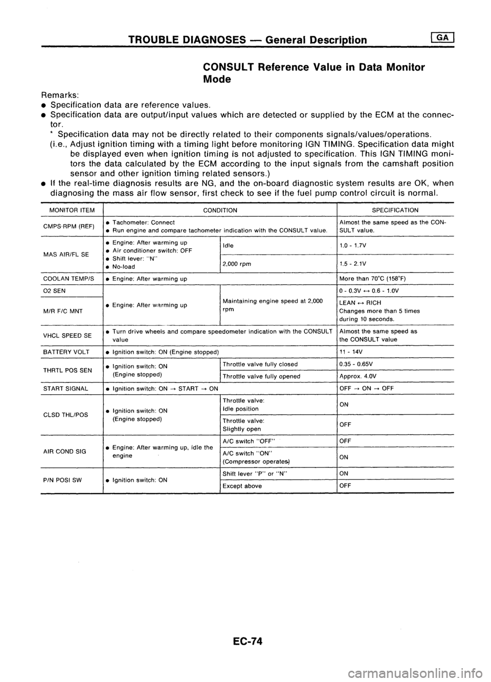
TROUBLEDIAGNOSES -General Description
CONSULT ReferenceValueinData Monitor
Mode
Remarks:
• Specification dataarereference values.
• Specification dataareoutput/input valueswhicharedetected orsupplied bythe ECM atthe connec-
tor.
*
Specification datamaynotbedirectly relatedtotheir components signals/values/operations.
(Le., Adjust ignition timingwithatiming lightbefore monitoring IGNTIMING. Specification datamight
be displayed evenwhen ignition timingisnot adjusted tospecification. ThisIGNTIMING moni-
tors thedata calculated bythe ECM according tothe input signals fromthecamshaft position
sensor andother ignition timingrelated sensors.)
• Ifthe real-time diagnosis resultsareNG, and theon-board diagnostic systemresultsareOK, when
diagnosing themass airflow sensor, firstcheck tosee ifthe fuel pump control circuitisnormal.
MONITOR ITEM
CONDITION SPEC
IFICA TION
CMPS.RPM (REF)•
Tachometer: Connect Almostthesame speed asthe CON-
• Run engine andcompare tachometer indicationwiththeCONSULT value.SULT value.
• Engine: Afterwarming up
Idle 1.0
-1.7V
MAS AIRIFL SE •
Air conditioner switch:OFF
• Shift lever: "N"
• No-load 2,000
rpm 1.5
-2.1V
COOLAN TEMPIS •Engine: Afterwarming up More
than70°C (158°F)
02 SEN 0-
0.3V
<-+
0.6 -1.0V
• Engine: Afterwflrming up Maintaining
enginespeedat2,000
LEAN
<-+
RICH
MIR
FIC
MNT rpm
Changesmorethan5times
during 10seconds .
VHCL SPEED SE•
Turn drive wheels andcompare speedometer indicationwiththeCONSULT Almost
thesame speed as
value the
CONSULT value
SA TTERY VOLT •Ignition switch:ON(Engine stopped) 11
-14V
• Ignition switch:ON Throttle
valvefullyclosed 0.35
-0.65V
THRTL POSSEN
(Enginestopped)
Throttlevalvefullyopened Approx.
4.0V
ST ART SIGNAL •Ignition switch:ON
-->
START
-->
ON OFF
-->
ON
-->
OFF
Throttle valve:
ON
• Ignition switch:ON Idle
position
CLSD THLIPOS
(Enginestopped)
Throttlevalve:
OFF
Slightly open
AIC
switch "OFF" OFF
AIR COND SIG •
Engine: Afterwarming up,idle the
engine
AIC
switch "ON"
ON
(Compressor operate&)
Shift lever "P"or"N" ON
PIN POSI SW •Ignition switch:ON
Exceptabove OFF
EC-74