1995 NISSAN ALMERA N15 Throttle valve
[x] Cancel search: Throttle valvePage 799 of 1701
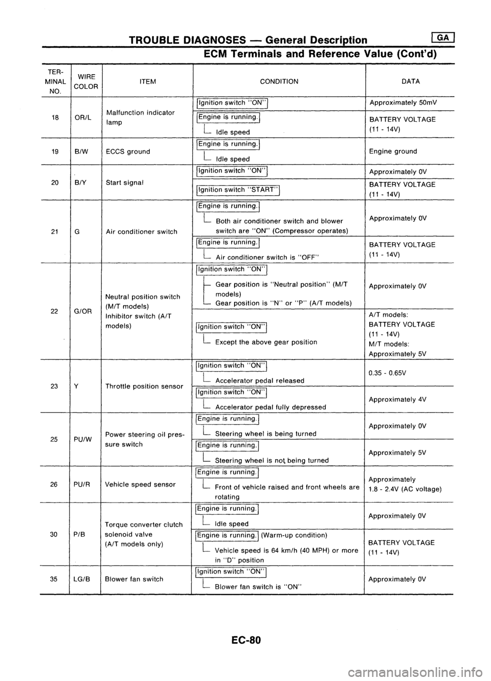
TROUBLEDIAGNOSES -General Description ~
ECM Terminals andReference Value(Cont'd)
TER- WIRE
MINAl ITEM CONDITION DATA
NO. COLOR
/'gnitionswitch"ON'" Approximately
50mV
18 OR/l Malfunction
indicator
I
Engine isrunning.
I
lamp BATTERY
VOLTAGE
L
Idle speed (11.14V)
19 BIW ECCS
ground
I
Engine isrunning.
I
Engineground
L
Idle speed
I'gnition switch"ON"
I
ApproximatelyOV
20 BIY
Startsignal
BATTERYVOLTAGE
I'gnition switch"5TART"
I
(11-14V)
I
Engine isrunning.
I
L
Both airconditioner switchandblower Approximately
OV
21 G Airconditioner switch switch
are"ON" (Compressor operates)
IEngine isrunning.
I
BATTERYVOLTAGE
L
Airconditioner switchis"OFF" (11
-14V)
I'gnition switch"ON'"
t
Ge.,
po,"'on "
"Ne"".1
po,ltlon"
(MIT
Approximately OV
Neutral position switch models)
(M/T
models) Gear
position is"N" or"P"
(A/T
models)
22
G/OR
Inhibitorswitch
(A/T AIT
models:
models) llgnitionswitch"ON'" BATTERY
VOLTAGE
L
Except theabove gearposition (11
-14V)
M/T
models:
Approximately 5V
Ilgnition switch"ON"
I
0.35-0.65V
L
Accelerator pedalreleased
23 Y Throttleposition sensor
!'gnitionswitch"ON"
I
L
Accelerator pedalfullydepressed Approximately
4V
/Engine isrunning.1
ApproximatelyOV
25 Pu/W Power
steering oilpres-
L
Steering wheelisbeing turned
sure switch
IEngineisrunning.1
L
Steering wheelisnot being turned Approximately
5V
I
Engine isrunning.
I
Approximately
26 PUIR Vehiclespeedsensor
L
Front ofvehicle raisedandfront wheels are
1.8-2.4V (ACvoltage)
rotating
I
Engine isrunning.
I
ApproximatelyOV
Torque converter clutch
L
Idle speed
30 PIB
solenoidvalve
I
Engine isrunning.
I
(Warm-up condition)
(A/T
models only)
L
Vehicle speedis64 km/h (40MPH) ormore BATTERY
VOLTAGE
(11-14V)
in "D" position
35 lG/B Blower
fanswitch I,gnition
switch"ON",
ApproximatelyOV
L
Blower fanswitch is"ON"
EC-80
Page 800 of 1701
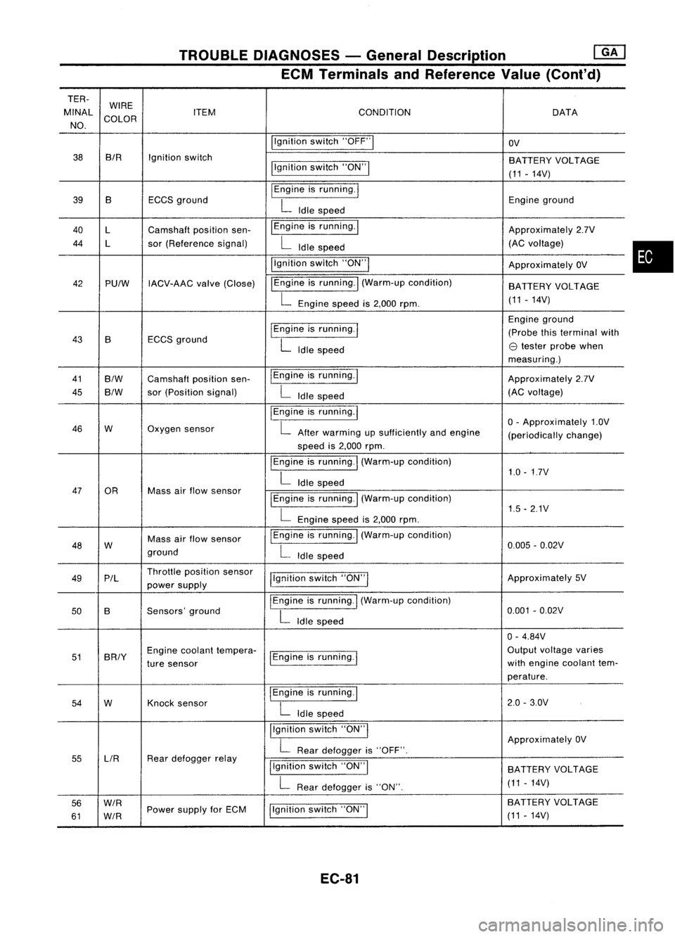
TROUBLEDIAGNOSES -General Description ~
ECM Terminals andReference Value(Cont'd)
TER-
MINAL WIRE
CONDITION
ITEM DATA
NO. COLOR
Ilgnitionswitch"OFF"1
OV
38 BIR
Ignitionswitch
BATTERYVOLTAGE
llgnition switch"ON"!
(11-14V)
39 B ECCSground
I
Engine isrunning.
I
Engineground
L
Idle speed
40 l Camshaft positionsen- I
Engine isrunning. I
Approximately2.7V
44 l sor(Reference signal)
L
Idle speed (AC
voltage)
i'gnition switch"ON'"
ApproximatelyOV
42 PUlW IACV-AAC valve(Close) IEngine
isrunning.
I
(Warm-up condition)
BATTERYVOLTAGE
L
Engine speedis2,000 rpm. (11
-14V)
I
Engine isrunning.
I
Engine
ground
43 B ECCS
ground (Probe
thisterminal with
L
Idle speed
e
tester probe when
measuring.)
41
B/W
Camshaft positionsen- IEngine
isrunning.1
Approximately2.7V
45
B/W
sor
(Position signal)
L
Idle speed (AC
voltage)
I
Engine isrunning.
I
o-
Approximately 1.0V
46 W Oxygen
sensor
L
After warming upsufficiently andengine
(periodicallychange)
speed is2,000 rpm.
I
Engine isrunning.
I
(Warm-up condition)
1.0-1.7V
L
Idle speed
47 OR Massairflow sensor
I
Engine isrunning.! (Warm-up condition)
L
Engine speedis2,000 rpm. 1.5
-2.1V
48 W Mass
airflow sensor
I
Engine isrunning. I(Warm-up condition)
0.005-0.02V
ground
L
Idle speed
49 P/l Throttle
position sensor
j!gnitionswitch"ON"I Approximately
5V
power supply
50 B Sensors'
ground
I
Engine isrunning.
I
(Warm-up condition)
0.001-0.02V
L
Idle speed
0-4.84V
51 BRIY Engine
coolant tempera-
1Engine isrunning.
I
Output
voltage varies
ture sensor with
engine coolant tem-
perature.
54 W Knock
sensor
I
Engine isrunning.!
2.0-3.0V
L
Idle speed
Ilgnition switch"ON'"
ApproximatelyOV
L
Rear defogger is"OFF".
55 LlR Rear
defogger relay
Ilgnitionswitch"ON"I
BATTERY VOLTAGE
L
Rear defogger is"ON". (11
-14V)
56
W/R
Ilgnitionswitch"ON"I BA
TTERY VOLTAGE
61
W/R
Power
supply forECM
(11-14V)
EC-81
•
Page 847 of 1701
TROUBLEDIAGNOSIS FORNON-DETECTABLE ITEMS
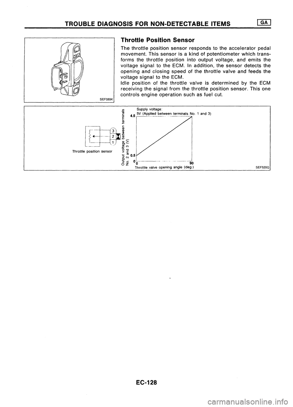
Throttle Position Sensor
The throttle position sensorresponds tothe accelerator pedal
movement. Thissensor isakind ofpotentiometer whichtrans-
forms thethrottle position intooutput voltage, andemits the
voltage signaltothe ECM. Inaddition, thesensor detects the
opening andclosing speedofthe throttle valveandfeeds the
voltage signaltothe ECM.
Idle position ofthe throttle valveisdetermined
by
the ECM
receiving thesignal fromthethrottle position sensor.Thisone
controls engineoperation suchasfuel cut.
SEF089K
CIl
Supplyvoltage:
r
-i.~h __
~3_
i
45
I
'V ,Appl.' b....
ffi
t~miMI,
No1,,'
31
~_ =r--=-tfr ~
I
l ~
1
N~
I
Throttle position sensor g
-g
'5 ::: 0.5
0-
'5
0 0----- -_.- --------_.
OZ 0 90
Throttle valveopening angle(deg_)
EC-128 SEF520Q
Page 851 of 1701
TROUBLEDIAGNOSIS FORNON-DETECTABLE ITEMS
Throttle Position Sensor(Cont'd)
~io
~ SEF461Q
II
~i8
ECM
E
CONNECTOR
II
20 23
@:
ForAustralia
@:
Except forAustralia
SEF229R
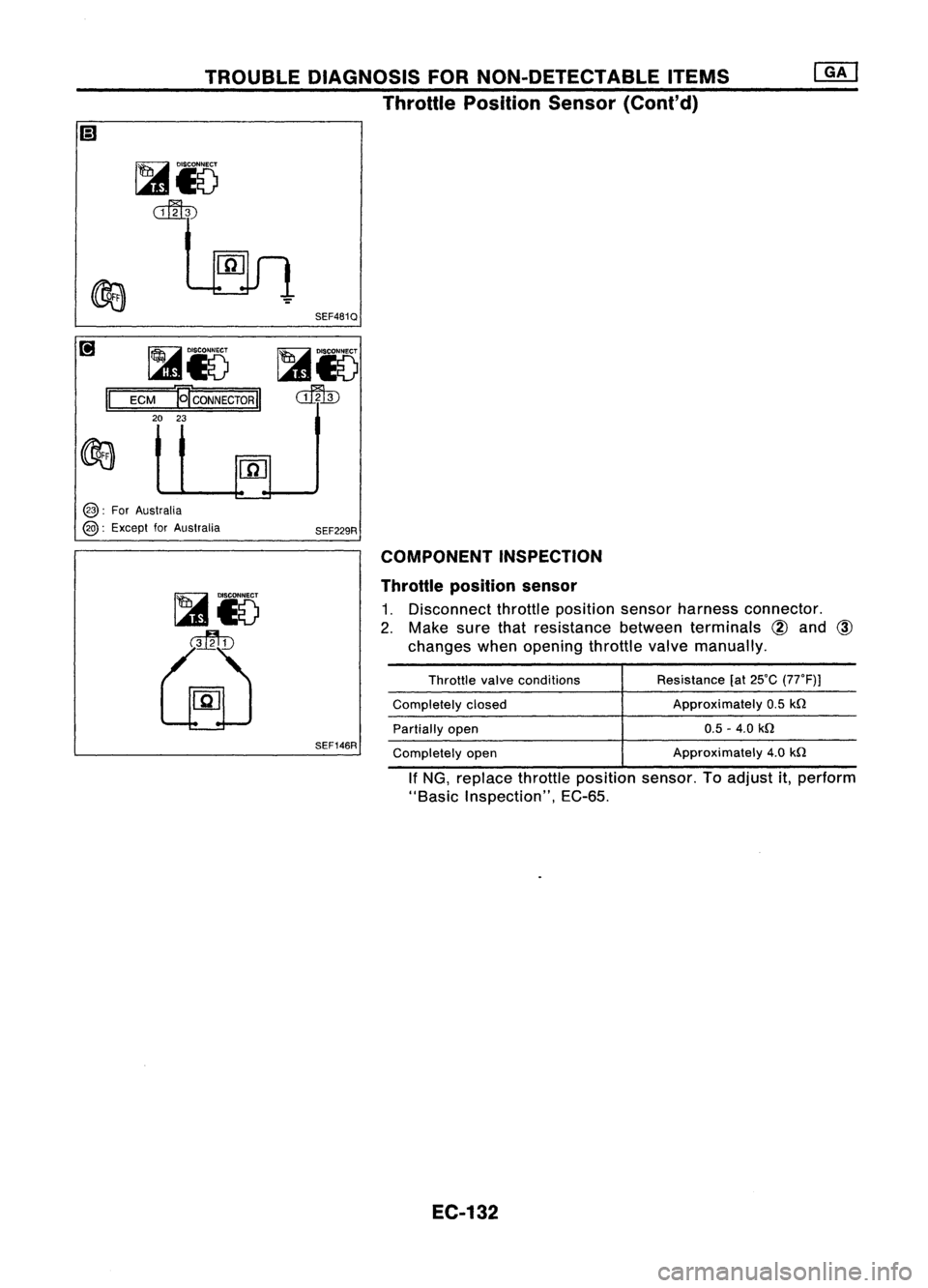
COMPONENT INSPECTION
Throttle position sensor
1. Disconnect throttleposition sensorharness connector.
2. Make surethatresistance betweenterminals
@
and
@
changes whenopening throttlevalvemanually.
SEF146R
Throttle
valveconditions
Completely closed
Partially open
Completely open Resistance
(at25'C (77'F)J
Approximately 0.5
kn
0.5 -4.0
kn
Approximately 4.0
kn
If NG, replace throttleposition sensor.Toadjust it,perform
"Basic Inspection", EC-65.
EC-132
Page 869 of 1701
TROUBLEDIAGNOSIS FORNON-DETECTABLE ITEMS
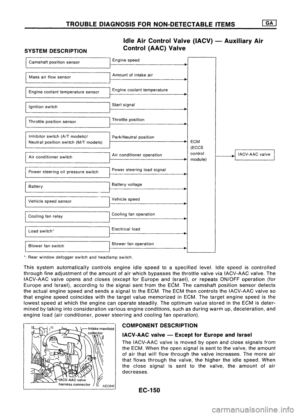
SYSTEM DESCRIPTION Idle
AirControl Valve(IACV) -Auxiliary Air
Control (AAC)Valve
Camshaft positionsensor Engine
speed
I
Mass
airflow sensor Amount
ofintake air
I
Engine coolant temperature sensor Engine
coolant temperature
~
I
Ignition switch Start
signal
I
Throttle positionsensor Throttle
position
~
I
Inhibitor switch(A/Tmodels)/
Park/Neutralposition
Neutral position switch(M/Tmodels) ECM
(ECCS
Air conditioner operation control
!
IACV-AAC valve
I
Air conditioner switch
module)
Power steering oilpressure switch Power
steering loadsignal
I
Battery
~
Battery voltage
Vehicle speedsensor Vehicle
speed
Cooling fanrelay Cooling
fanoperation
Load switch' Electrical
load
Blower fanswitch Blower
fanoperation
': Rear window defogger switchandheadlamp switch.
This system automatically controlsengineidlespeed toaspecified level.Idlespeed iscontrolled
through fineadjustment ofthe amount ofair which bypasses thethrottle valveviaIACV-AAC valve.The
IACV-AAC valveopens andcloses (except forEurope andIsrael), orrepeats ON/OFF operation (for
Europe andIsrael), according tothe signal sentfrom theECM. Thecamshaft positionsensordetects
the actual engine speedandsends asignal tothe ECM. TheECM thencontrols theIACV-AAC valveso
that engine speedcoincides withthetarget valuememorized inECM. Thetarget engine speedisthe
lowest speedatwhich theengine canoperate steadily. Theoptimum valuestored inthe ECM isdeter-
mined bytaking intoconsideration variousengineconditions, suchasduring warmup,deceleration, and
engine load(airconditioner, powersteering andcooling fanoperation).
COMPONENT DESCRIPTION
IACV-AAC valve-Except forEurope andIsrael
The IACV-AAC valveismoved byopen andclose signals from
the ECM. When theopen signal issent tothe valve, theamount
of air that willflow through thevalve increases. Themore air
that flows through thevalve, thehigher theidle speed. When
the close signal issent tothe valve. theamount ofair
decreases.
EC-150
Page 873 of 1701
Repairharness orcon-
nectors. INSPECTION
END
Check thefollowing.
• Harness connectors
QD,@orQD,
@
• 10A fuse
• Harness foropen or
short between IACV-AAC
valve andfuse
If NG, repair harness or
connectors.
NG OK
NG
OK
INSPECTION
START
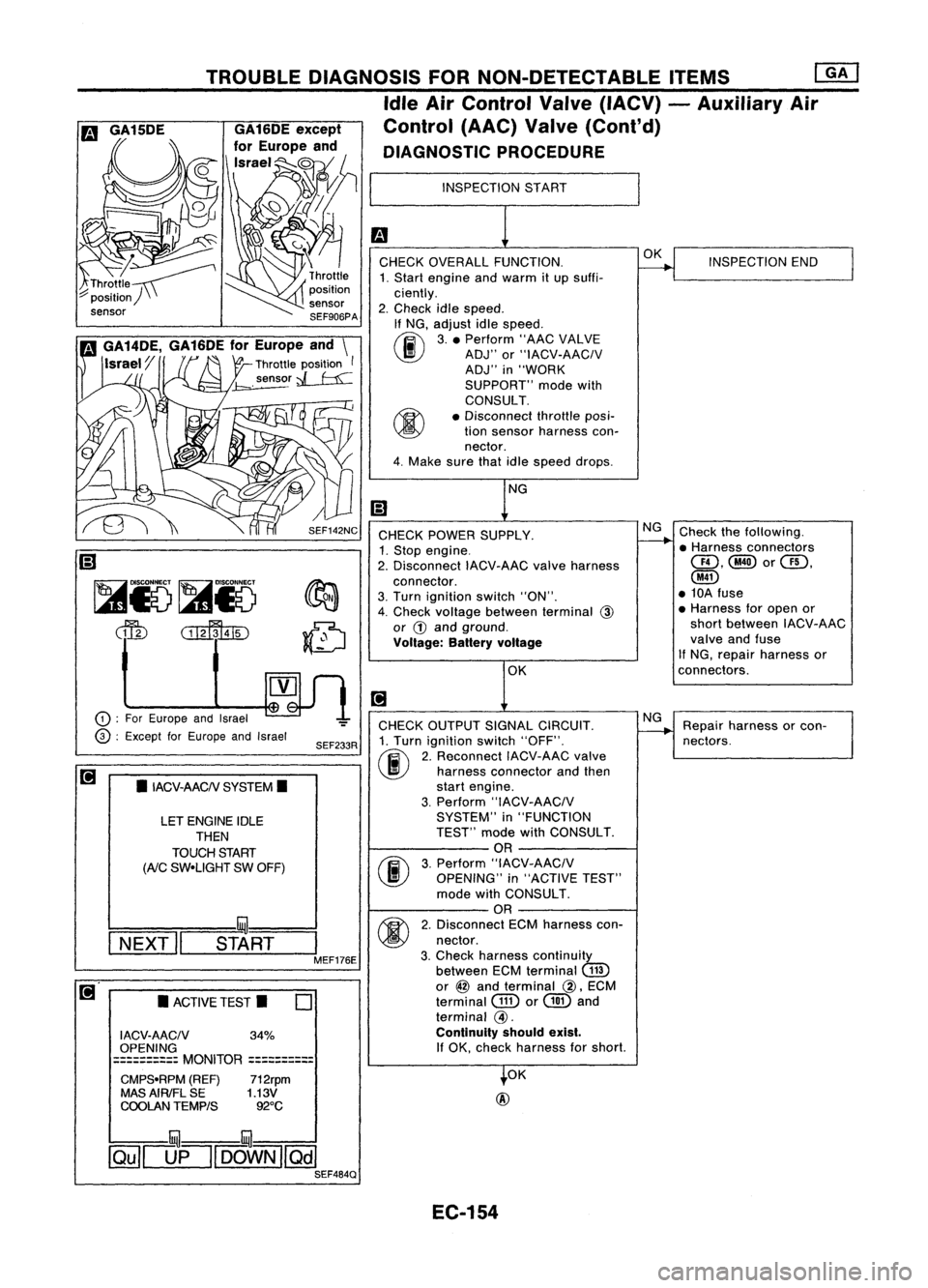
CHECK OVERALL FUNCTION.
1. Start engine andwarm itup suffi-
ciently.
2. Check idlespeed.
If NG, adjust idlespeed.
~ 3.• Perform "AACVALVE
~ ADJ"or"IACV-AACIV
ADJ" in"WORK
SUPPORT" modewith
CONSULT.
• Disconnect throttleposi-
tion sensor harness con-
nector.
4. Make surethatidlespeed drops.
OK
@
CHECK
POWER SUPPLY.
1. Stop engine.
2. Disconnect IACV-AACvalveharness
connector.
3. Turn ignition switch"ON".
4. Check voltage between terminal
@
or
G)
and ground.
Voltage: Batteryvoltage
CHECK OUTPUT SIGNALCIRCUIT.
1. Turn ignition switch"OFF".
(ij\
2.Reconnect IACV-AACvalve
~ harnessconnector andthen
start engine.
3. Perform "IACV-AACIV
SYSTEM" in"FUNCTION
TEST" modewithCONSULT.
OR
(F.I\
3.Perform "IACV-AACIV
~ OPENING" in"ACTIVE TEST"
mode withCONSULT.
OR
M
2.Disconnect ECMharness con-
~ nectar.
3. Check harness continuity
between ECMterminal
(ill)
or
@
and terminal
@,
ECM
terminal
GID
or
@
and
terminal
@.
Continuity shouldexist.
If
OK, check harness forshort.
SEF233R
SEF142NC
o
•
ACTIVE TEST.
LET
ENGINE IDLE
THEN
TOUCH START
(AiC
SW-UGHT SWOFF)
•
IACV-AACN SYSTEM.
I ACV-AACN 34%
OPENING
==========
MONITOR
==========
CMPS-RPM (REF)712rpm
MAS AIRIFL SE 1.13V
COOLAN TEMPtS 92°C
TROUBLE
DIAGNOSIS FORNON-DETECTABLE ITEMS
ffiJ
Idle AirControl Valve(IACV) -Auxiliary Air
Control (AAC)Valve(Cont'd)
DIAGNOSTIC PROCEDURE
!:::=====mul===
I
NEXT" START
I
MEF176E
CD
:
For Europe andIsrael
@ :
Except forEurope andIsrael
~
Ii)
~i5~i5
dfu
CillffuID
illU--illU
~[]fl[OOWN][Qill SEF484Q
EC-154
Page 898 of 1701
TROUBLEDIAGNOSIS FORNON-DETECTABLE ITEMS
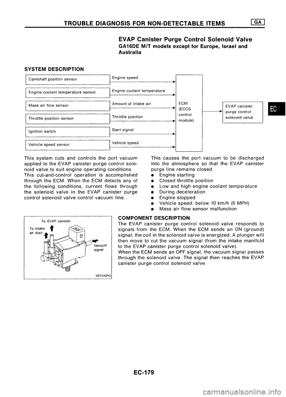
EVAP Canister PurgeControl Solenoid Valve
GA16DE MITmodels exceptforEurope, Israeland
Australia
SYSTEM DESCRIPTION
Camshaft positionsensor
Engine coolant temperature sensor
Mass airflow sensor
Throttle positionsensor
Ignition switch
Vehicle speedsensor Engine
speed
Engine coolant temperature
Amount ofintake air
Throttle position
Start signal
Vehicle speed ECM
(ECCS
control
module) EVAP
canister
purge control
solenoid valve
•
This system cutsandcontrols theport vacuum
applied tothe EVAP canister purgecontrol sole-
noid valve tosuit engine operating conditions.
This cut-and-control operationisaccomplished
through theECM. When theECM detects anyof
the following conditions, currentflowsthrough
the solenoid valveinthe EVAP canister purge
control solenoid valvecontrol vacuum line. This
causes theport vacuum tobe discharged
into theatmosphere sothat theEVAP canister
purge lineremains closed.
• Engine starting
• Closed throttle position
• Low andhigh engine coolant temperature
• During deceleration
• Engine stopped
• Vehicle speed:below10km/h (6MPH)
• Mass airflow sensor malfunction
W>
Vacuum
signal
SEF240PG COMPONENT
DESCRIPTION
The EVAP canister purgecontrol solenoid valveresponds to
signals fromtheECM. When theECM sends anON (ground)
signal, thecoil inthe solenoid valveisenergized. Aplunger will
then move tocut the vacuum signal(fromtheintake manifc,ld
to the EVAP canister purgecontrol solenoid valve).
When theECM sends anOFF signal, thevacuum signalpasses
through thesolenoid valve.Thesignal thenreaches theEVAP
canister purgecontrol solenoid valve.
EC-179
Page 902 of 1701
TROUBLEDIAGNOSIS FORNON-DETECTABLE ITEMS
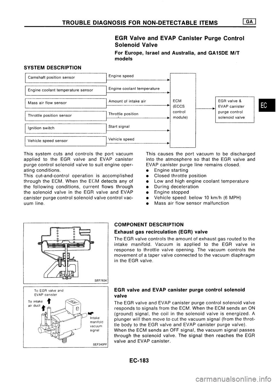
EGR Valve andEVAP Canister PurgeControl
Solenoid Valve
For Europe, IsraelandAustralia, andGA15DE MIT
models
SYSTEM DESCRIPTION
Camshaft positionsensor
Engine coolant temperature sensor
Mass airflow sensor
Throttle position sensor
Ignition switch
Vehicle speedsensor Engine
speed
Engine coolant temperature
Amount ofintake air
Throttle position
Start signal
Vehicle speed ECM
(ECCS
control module) EGR
valve
&
EVAP canister
purge control
solenoid valve
•
This system cutsandcontrols theport vacuum
applied tothe EGR valve andEVAP canister
purge control solenoid valvetosuit engine oper-
ating conditions.
This cut-and-control operationisaccomplished
through theECM. When theECM detects anyof
the following conditions, currentflowsthrough
the solenoid valveinthe EGR valve andEVAP
canister purgecontrol solenoid valvecontrol vac-
uum line. This
causes theport vacuum tobe discharged
into theatmosphere sothat theEGR valve and
EVAP canister purgelineremains closed.
• Engine starting
• Closed throttle position
• Low andhigh engine coolant temperature
• During deceleration
• Engine stopped
• Vehicle speed:below10km/h (6MPH)
• Mass airflow sensor malfunction
SEF783K
l#
Intake
manifold
vacuum signal
SEF240PF COMPONENT
DESCRIPTION
Exhaust gasrecirculation (EGR)valve
The EGR valve controls theamount ofexhaust gasrouted tothe
intake manifold. Vacuumisapplied tothe EGR valve in
response tothrottle valveopening. Thevacuum controls the
movement ofataper valve connected tothe vacuum diaphragm
in the EGR valve.
EGR valve andEVAP canister purgecontrol solenoid
valve
The EGR valve andEVAP canister purgecontrol solenoid valve
responds tosignals fromtheECM. When theECM sends anON
(ground) signal,thecoil inthe solenoid valveisenergized. A
plunger willthen move tocut the vacuum signal(fromthethrot-
tle body tothe EGR valve andEVAP canister purgevalve).
When theECM sends anOFF signal, thevacuum signalpasses
through thesolenoid valve.Thesignal thenreaches theEGR
valve andEVAP canister.
EC-183