Page 1617 of 1701

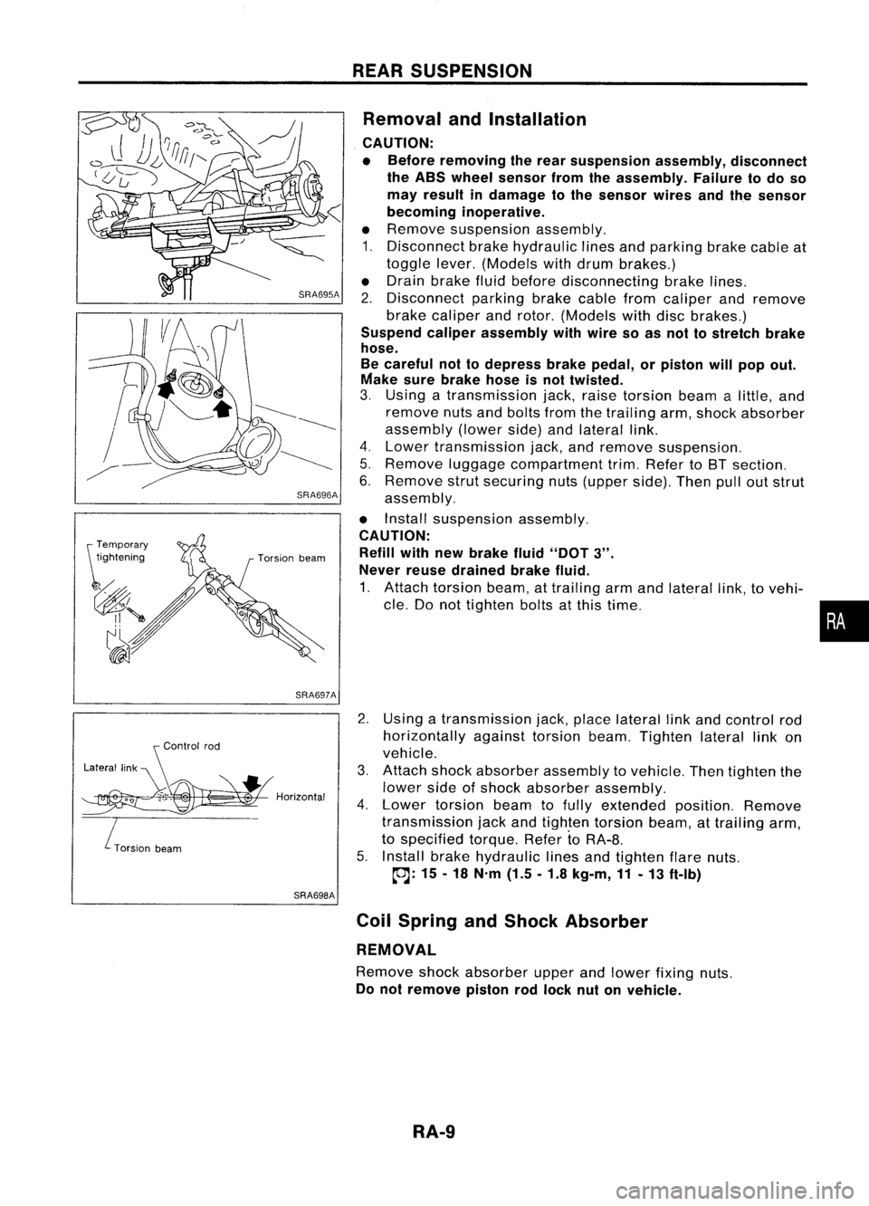
SRA696A
SRA697A
S
Control rod
Lateral link
~H";""I"
ITorsion
beam
SRA698AREAR
SUSPENSION
Removal andInstallation
CAUTION:
• Before removing therear suspension assembly,disconnect
the ABS wheel sensor fromtheassembly. Failuretodo so
may result indamage tothe sensor wiresandthesensor
becoming inoperative.
• Remove suspension assembly.
1. Disconnect brakehydraulic linesandparking brakecableat
toggle lever.(Models withdrum brakes.)
• Drain brake fluidbefore disconnecting brakelines.
2. Disconnect parkingbrakecablefromcaliper andremove
brake caliper androtor. (Models withdiscbrakes.)
Suspend caliperassembly withwire soasnot tostretch brake
hose.
Be careful nottodepress brakepedal, orpiston willpop out.
Make surebrake hoseisnot twisted.
3. Using atransmission jack,raise torsion beamalittle, and
remove nutsandbolts fromthetrailing arm,shock absorber
assembly (lowerside)andlateral link.
4. Lower transmission jack,andremove suspension.
5. Remove luggagecompartment trim.Refer toBT section.
6. Remove strutsecuring nuts(upper side).Thenpulloutstrut
assembly.
• Install suspension assembly.
CAUTION: Refill withnewbrake fluid"DOT
3".
Never reusedrained brakefluid.
1. Attach torsion beam,attrailing armandlateral link,tovehi-
cle. Donot tighten boltsatthis time.
2. Using atransmission jack,place lateral linkand control rod
horizontally againsttorsionbeam.Tighten laterallinkon
vehicle.
3. Attach shockabsorber assembly tovehicle. Thentighten the
lower sideofshock absorber assembly.
4. Lower torsion beamtofully extended position.Remove
transmission jackandtighten torsion beam,attrailing arm,
to specified torque.RefertoRA-8.
5. Install brakehydraulic linesandtighten flarenuts.
~: 15-18 N'm (1.5.1.8 kg-m,11-13 ft-Ib)
Coil Spring andShock Absorber
REMOVAL
Remove shockabsorber upperandlower fixing nuts.
Do not remove pistonrodlock nutonvehicle.
RA-9
•
Page 1620 of 1701
SERVICEDATAANDSPECIFICATIONS (50S)
General Specifications
Suspension type
Shock absorber type
Stabilizer Multi-link
beamsuspension
Double-acting hydraulic
Standard equipment
WHEEL ALIGNMENT (Unladen*) Inspection
andAdjustment
WHEEL BEARING
Camber Minimum-1'45'
(-1.75')
Degree minute Nominal
-1'00'
(-1.00')
(Decimal degree) Maximum -0'15'
(-0.25')
Total toe-in Minimum-3
(-0.12)
Distance (A-B) Nominal
1
(0.04)
mm (in) Maximum 5(0.20)
Angle (leftpius right) Minimum -16'(-0.27')
Degree minute Nominal
5'
(0.08')
(Decimal degree)Maximum 26'
(0.43') Wheel
bearing axialendplay
mm (in)
Wheel bearing locknuttighten-
ing torque
N'm(kg-m. ft-lb) 0.05
(0.0020) orless
186 -255
(19 -26, 137 -188)
': Fuel, radiator coolantandengine oilfull. Spare tire.jack, hand
tools andmats indesignated positions.
RA-12
Page 1669 of 1701
Toolnumber
Tool name PRECAUTIONS
ANDPREPARATION
Special Service Tools
Description
KV481 00700
Torque adapter
KV481 02500
Pressure gaugeadapter NT169
NT542 PF3/B"~
@
@
PF3/B"~ ~x1.5 pitch
M16 x1.5 pitch Measuring
pinionrotating torque
Measuring oilpressure
ST27180001
Steering wheelpuller
NT544(1.14
in)
@Q'O
,'25 0;'0'
@ @
MB
x1.25 pitch Removing
andinstalling steeringwheel
HT72520000
Ball joint remover
ST27091000 Pressure gauge
KV481 04400
Rack sealringreformer
ST3127S000
G)
GG91030000
Torque wrench
@ HT62940000
Socket adapter
@
HT62900000
Socket adapter NT546
NT547
NT550
NT541 To
control valve
Shut-off valve
~ 1/4"~rque wrench
~ withrange of
1/4"
to
3/B" 2.9
N.m
~ ""(30kg-em,
'V
'td"
3/B
to
1/2
26
in-Ib)
ST-3 Removing
balljoint
a:
33
mm
(1.30
in)
b: 50
mm
(1.97
in)
r:
R11.5
mm
(0.453
in)
Measuring oilpressure
Reforming teflonring
a: 50 mm (1.97 in)dia.
b: 36 mm (1.42 in)dia.
c:
100
mm
(3.94
in)
Measuring turningtorque
•
Page 1680 of 1701
MANUALSTEERING GEARANDLINKAGE (ModelR24N)
Removal andInstallation
SEC. 480
A :
N.m (kg-m, tt-Ib)
(!)
Hole cover
@
Lower joint
@
Manual steering gearassembly
@
Steering gearmounting clamp
tt'J
29•39
(3.0 -4.0,22 -", ~
~
@~ SST056CA
@
Rack mounting insulator
@
Cotter pin
CAUTION:
The rotation ofthe spiral cable(SRS"Airbag" component part)
is limited.
If
the steering gearmust beremoved, setthe front
wheels inthe straight-ahead direction.Donot rotate thesteer-
ing column whilethesteering gearisremoved.
• Detach tie-rodoutersockets fromknuckle armswithTool.
• Initially, tightennutontie-rod outersocket andknuckle arm
to 29 to39 N'm (3to 4kg-m, 22to29 ft-Ib).
• Tighten nutfurther toalign nutgroove withthefirst pinhole
so cotter pincan beinstalled.
CAUTION:
Tightening torquemustnotexceed 49N.m (5kg-m, 36ft-Ib).
ST-14
Page 1686 of 1701

POWERSTEERING GEARANDLINKAGE (ModelPR24AC)
Removal andInstallation (Cont'd)
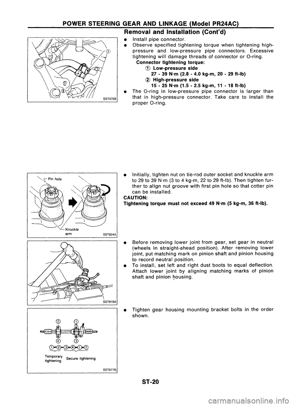
• Install pipeconnector.
• Observe specified tightening torquewhentightening high-
pressure andlow-pressure pipeconnectors. Excessive
tightening willdamage threadsofconnector orO-ring.
Connector tighteningtorque:
CD
Low-pressure side
27 -39 N'm (2.8-4.0 kg-m, 20-29 ft-Ib)
~ High-pressure side
15 -25 N'm (1.5-2.5 kg-m, 11-18 ft-Ib)
• The O-ring inlow-pressure pipeconnector islarger than
that inhigh-pressure connector.Takecaretoinstall the
proper O-ring.
• Initially, tightennutontie-rod outersocket andknuckle arm
to 29 to39 N'm (3to 4kg-m, 22to29 ft-Ib). Thentighten fur-
ther toalign nutgroove withfirstpinhole sothat cotter pin
can beinstalled.
CAUTION:
Tightening torquemustnotexceed 49N'm (5kg-m, 36ft-Ib).
• Before removing lowerjointfrom gear, setgear inneutral
(wheels instraight-ahead position).Afterremoving lower
joint, putmatching markonpinion shaftandpinion housing
to record neutral position.
• Toinstall, setleftand right dustboots toequal deflection.
Attach lowerjointbyaligning matching marksofpinion
shaft andpinion ~ousing.
• Tighten gearhousing mounting bracketboltsinthe order
shown.
o
@
~
'--v---' ~
Temporary ..
tightening SecuretIghtening
SST6778
ST-20
Page 1701 of 1701

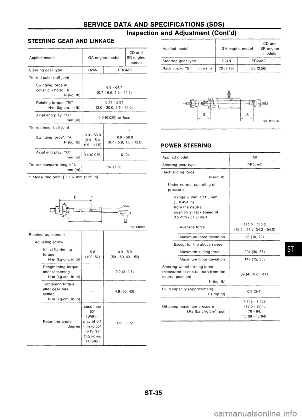
SERVICEDATAANDSPECIFICATIONS (50S)
Inspection andAdjustment (Cont'd)
STEERING GEARANDLINKAGE
CDand
Applied model GA
engine model SRengine
models
Steering geartype R24NPR24AC
Tie-rod outerballjoint
Swinging forceat
6.9-64.7
cotter pinhole: "A"
(0.7-6.6, 1.5-14.6)
N (kg, Ib)
Rotating torque:"B" 0.29
-294
N'm (kg-em, in-Ib) (30
-30.0, 26-260)
Axial endplay: "C"
0.5(0.020) orless
mm (in)
Tie-rod innerballjoint
.
Swinging force":"A" 3.9
-53.0
6.9-569
(0.4 -5.4,
N (kg, Ib)
0.9-11.9) (07
-58,1.5 -12.8)
Axial endplay: "C"
0.4(0.016)
a
(0)
mm (in)
Tie-rod standard length"L"
187(7.36)
mm (in)
". Measuring point
[f:
137 mm (5.39 in)]
SST488C
Retainer adjustment
Adjusting screw
Initial tightening
984.9
-5.9
torque (100,87)(50-60, 43-52)
Nm (kg-em, in-Ib)
Retightening torque
after loosening
-
02
(2,1.7)
N'm (kg-em, in-Ib)
Tightening torque
after gear has
-
49(50, 43)
settled
N'm (kg-em, in-Ib)
Lessthan
60'
[Within
Returning angle play
of0.1
70'-110'
degree mm
(0.004
in)/15 N'm
(1.5 kg-m,
11 ft-Ib)] CD
and
Applied model GAengine model SRengine
models
Steering geartype R24N
PR24AC
Rack stroke "S" mm(in) 70(2.76) 65(2.56)
POWER STEERING
Applied model All
Steering geartype PR24AC
Rack sliding force
N(kg, Ib)
Under normal operating oil
pressure
Range within ~.115 mm
(:1:0.453 in)
from theneutral
position atrack speed of
3.5 mm (0.138 in)/s
Average force 1520
-2403
(15.5 -24.5, 34.2-54.0)
Maximum forcedeviation 98(10, 22)
Except forthe above range
Maximum slidingforce 294(30, 66)
Maximum forcedeviation 147
(15, 33)
Steering wheelturning force
(Measured atone fullturn from the
39(4, 9)or less
neutral position)
N(kg, Ib)
Fluid capacity (Approximate)
0.9(3/4)
f
(Imp qt)
7,649-8,238
Oil pump maximum pressure (76.5
-82.4,
kPa (bar, kg/em?, psi) 78-84,
1,109 -1,194)
•
ST-35
Page:
< prev 1-8 9-16 17-24