Page 940 of 1701

TROUBLEDIAGNOSIS FORNON-DETECTABLE ITEMS~
Torque Converter ClutchSolenoid Valve(Cont'd)
SYSTEM DESCRIPTION
Throttle position sensor Throttle
valveopening angle
Engine coolant temperature sensorEnginecoolant temperature ECM
(ECCS
control
module) Torque
converter
clutch solenoid
valve
Vehicle speedsensor Vehicle
speed
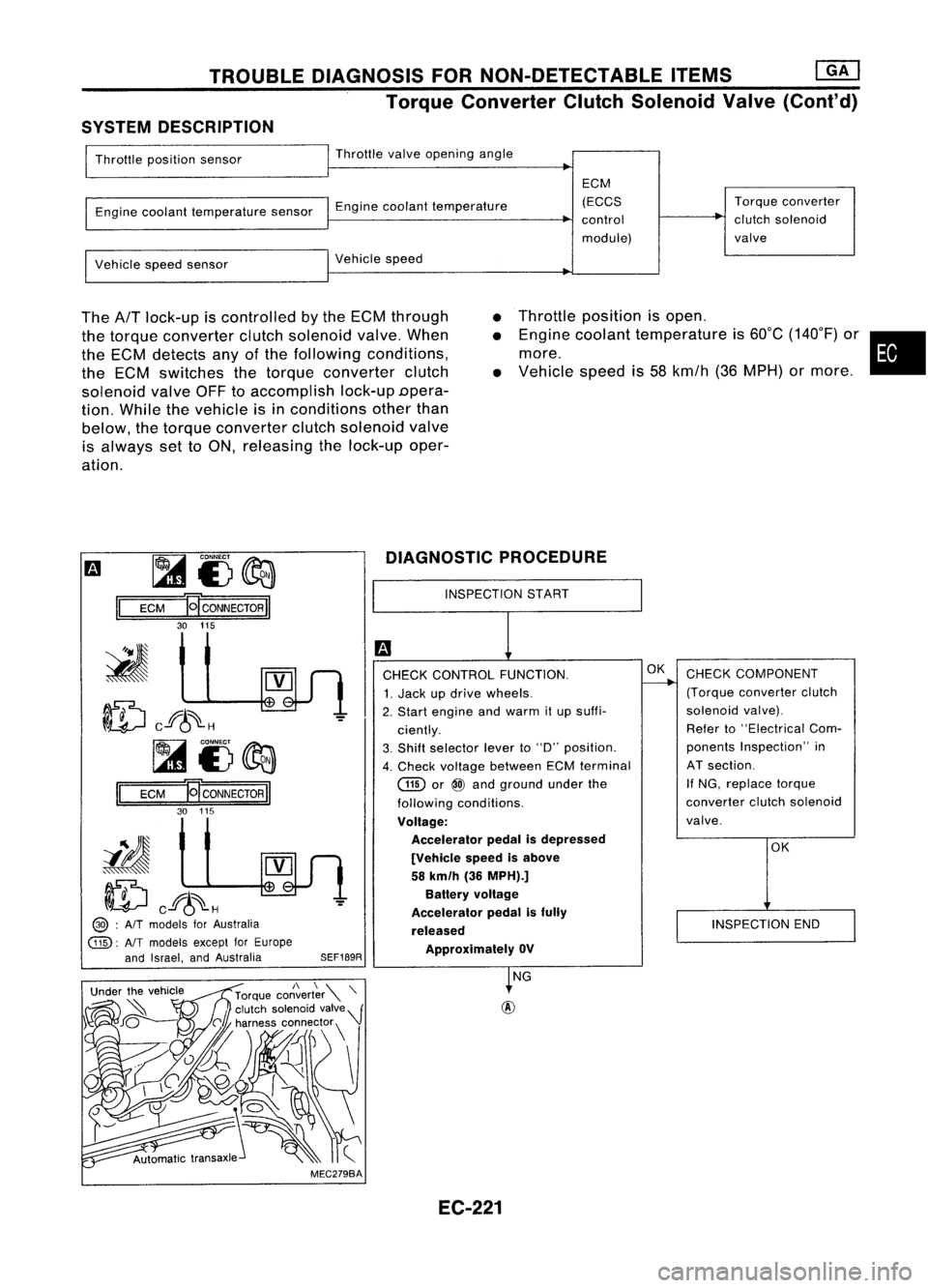
The
AfT
lock-up iscontrolled bythe ECM through
the torque converter clutchsolenoid valve.When
the ECM detects anyofthe following conditions,
the ECM switches thetorque converter clutch
solenoid valveOFFtoaccomplish lock-upDpera-
tion. While thevehicle isin conditions otherthan
below, thetorque converter clutchsolenoid valve
is always settoON, releasing thelock-up oper-
ation.
•
•
•
Throttle
position isopen .
Engine coolant temperature is60°C (140°F) or•
more.
Vehicle speedis58 kmfh (36MPH) ormore .
m ~
i3~
II
ECM
HCONNECTORII
30 115
ID
cf6~H
~i3~
II
ECM E
CONNECTOR
II
30 115
iIJ
ID
cf6~H
@> :
AIT
models forAustralia
@:
AlTmodels exceptforEurope
and Israel, andAustralia
SEF189RDIAGNOSTIC
PROCEDURE
INSPECTION START
CHECK CONTROL FUNCTION.
1. Jack updrive wheels.
2. Start engine andwarm itup suffi-
ciently.
3. Shift selector leverto"D" position.
4. Check voltage between ECMterminal
GID
or
@
and ground underthe
following conditions.
Voltage: Accelerator pedalisdepressed
[Vehicle speedisabove
58 km/h (36MPH).]
Battery voltage
Accelerator pedalisfully
released ApprOXimately OV
OK
CHECK COMPONENT
(Torque converter clutch
solenoid valve).
Refer to"Electrical Com-
ponents Inspection" in
AT section.
If NG, replace torque
converter clutchsolenoid
valve.
OK
INSPECTION END
MEC279BA NG
EC-221
Page 1004 of 1701
![NISSAN ALMERA N15 1995 Service Manual TROUBLEDIAGNOSIS -General Description
[]K]
ECM Terminals andReference Value(Cont'd)
'Data arereference values.
TERMINAL WIRE
ITEM CONDITION
'DATA
NO. COLOR
Ilgnitionswitch"ON"I
NISSAN ALMERA N15 1995 Service Manual TROUBLEDIAGNOSIS -General Description
[]K]
ECM Terminals andReference Value(Cont'd)
'Data arereference values.
TERMINAL WIRE
ITEM CONDITION
'DATA
NO. COLOR
Ilgnitionswitch"ON"I](/manual-img/5/57349/w960_57349-1003.png)
TROUBLEDIAGNOSIS -General Description
[]K]
ECM Terminals andReference Value(Cont'd)
'Data arereference values.
TERMINAL WIRE
ITEM CONDITION
'DATA
NO. COLOR
Ilgnitionswitch"ON"I
L
For 5seconds afterturning ignition switch
"ON" Approximately
OV
104 B/P Fuelpump relay !Engine
isrunning.1
Ilgnition switch"ON"I
BATTERY VOLTAGE
L
5seconds afterturning ignitionswitch
(11-14V)
"ON" andthereafter
IEngine isrunning.1
0.6-0.8V
EGR valve
&
EVAP
.L
Engine speedis4,000 rpm.
105 P canisterpurgecontrol
solenoid valve IEngine
isrunning.1
BATTERYVOLTAGE
L
Idle speed (11
-14V)
107 IEngine
isrunning.j
B/Y ECCSground
L
Engine
ground
108 Idlespeed
!Engine isrunning.1
Approximately0.2V
L
Engine speedisbelow 3,200rpm.
Heated oxygen sensor
111 OR
heater IEngineisrunning.1
BATTERY VOLTAGE
L
Engine speedisabove 3,200rpm. (11
-14V)
IEngine isrunning.\
11-14V
L
Idle speed
113 SB IACV-AAC
valve lEngine
isrunning.1
~ Sle«;ng wheel;,be;ng I"med
2-11V
Air conditioner isoperating.
Rear window defogger switchis"ON".
Lighting switchis"ON".
!Engine isrunning.1
ApproximatelyOV
Torque converter
L
Idle speed
115 P/B clutch
solenoid valve
IEngineisrunning.1 (Warm-up condition)
(A/T
models)
L
Vehicle speedis60 km/h (37MPH) or BA
TTERY VOLTAGE
(11 -14V)
more in"D" position
116 BIY ECCS
ground IEngine
isrunning.1
Engineground
L
Idle speed
EC-285
•
Page 1087 of 1701

TROUBLEDIAGNOSIS FORNON-DETECTABLE ITEMS~
Torque Converter ClutchSolenoid Valve(Cont'd)
SYSTEM DESCRIPTION
Throttle position sensor Throttle
valveopening angle
Engine coolant temperature sensorEnginecoolant temperature ECM
(ECCS
control
module) Torque
converter
clutch solenoid
valve
Vehicle speedsensor Vehicle
speed
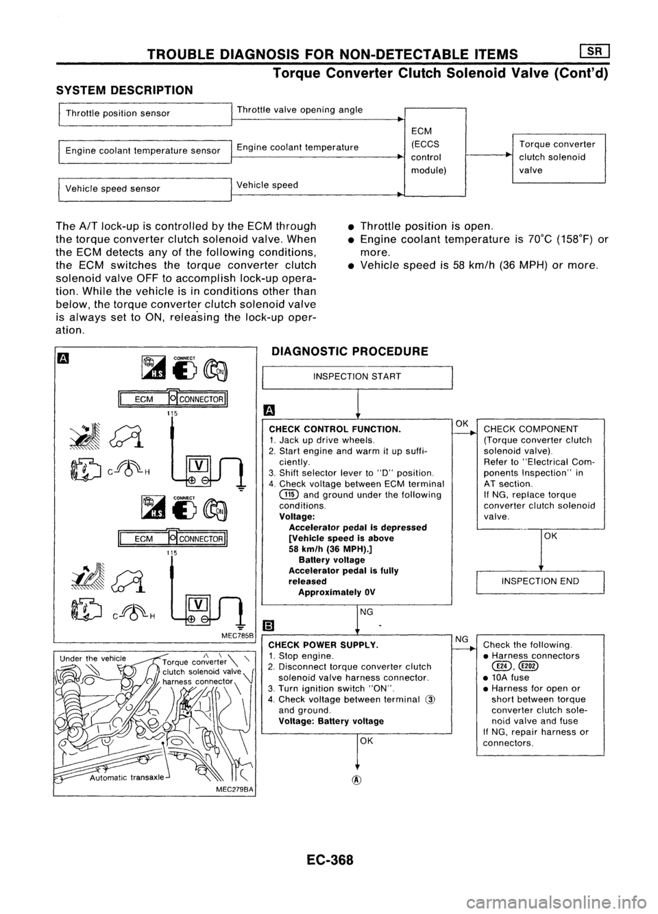
The
AfT
lock-up iscontrolled bythe ECM through
the torque converter clutchsolenoid valve.When
the ECM detects anyofthe following conditions,
the ECM switches thetorque converter clutch
solenoid valveOFFtoaccomplish lock-upopera-
tion. While thevehicle isinconditions otherthan
below, thetorque converter clutchsolenoid valve
is always settoON, relea'sing thelock-up oper-
ation. •
Throttle position isopen .
• Engine coolant temperature is70°C (158°F) or
more .
• Vehicle speedis58 kmfh (36MPH) ormore.
~i3~
II
ECM
E[CONNECTORII
DIAGNOSTIC
PROCEDURE
INSPECTION START
115
OK
INSPECTION END
CHECK
COMPONENT
(Torque converter clutch
solenoid valve).
Refer to"Electrical Com-
ponents Inspection" in
AT section.
If
NG, replace torque
converter clutchsolenoid
valve.
Check thefollowing.
• Harness connectors
@,
• 10A fuse
• Harness foropen or
short between torque
converter clutchsole-
noid valve andfuse
If NG, repair harness or
connectors.
NG
OK
OK
@
CHECK
CONTROL FUNCTION.
1. Jack updrive wheels.
2. Start engine andwarm itup suffi-
ciently.
3. Shift selector leverto"0" position.
4. Check voltage between ECMterminal
GID
andground underthefollowing
conditions.
Voltage: Accelerator pedalIsdepressed
[Vehicle speedisabove
58 km/h (36MPH).]
Battery voltage
Accelerator pedalisfully
released
Approximately OV
CHECK POWER SUPPLY.
1. Stop engine.
2. Disconnect torqueconverter clutch
solenoid valveharness connector.
3. Turn ignition switch"ON".
4. Check voltage between terminal
@
and ground.
Voltage: Batteryvoltage
-
MEC785B
MEC279BA
Ef
CONNECTOR
II
115
II
ECM
~~
ID
cf8~-H
EC-368
Page 1355 of 1701

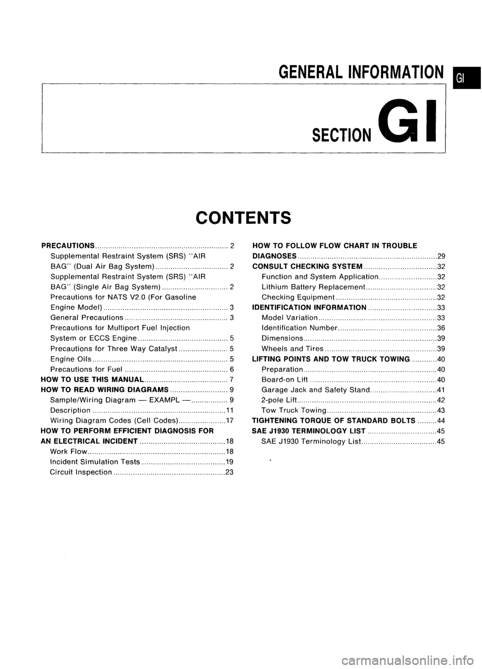
GENERALINFORMATION •
SECTION
G
I
CONTENTS
PRECAUTIONS 2
Supplemental RestraintSystem(SRS)"AIR
BAG" (DualAirBag System) 2
Supplemental RestraintSystem(SRS)"AIR
BAG" (Single AirBag System) 2
Precautions forNATS V2.0(ForGasoline
Engine Model) 3
General Precautions 3
Precautions forMultiport FuelInjection
System orECCS Engine 5
Precautions forThree WayCatalyst 5
Engine Oils 5
Precautions forFuel 6
HOW TOUSE THIS
MANUAL 7
HOW TOREAD WIRING DIAGRAMS 9
Sample/Wiring Diagram-EXAMPL - 9
Description 11
Wiring Diagram Codes(CellCodes) 17
HOW TOPERFORM EFFICIENT DIAGNOSIS FOR
AN ELECTRICAL INCIDENT 18
Work Flow 18
Incident Simulation Tests 19
Circuit Inspection 23
HOW
TOFOLLOW FLOWCHART INTROUBLE
DIAGNOSES 29
CONSULT CHECKING SYSTEM
32
Function andSystem Application 32
Lithium BatteryReplacement.. 32
Checking Equipment 32
IDENTIFICATION INFORMATION 33
Model Variation 33
Identification Number 36
Di mens ions 39
Wheels andTires 39
LIFTING POINTSANDTOW TRUCK TOWING ..40
Preparation 40
Board-on
Lift
40
Garage JackandSafety Stand 41
2-pole Lift 42
Tow Truck Towing 43
TIGHTENING TORQUEOFSTANDARD BOLTS
44
SAE J1930 TERMINOLOGY LIST 45
SAE J1930 Terminology List.. 45
Page 1536 of 1701

0
0
•
0
0
~ /0
H
H
0
0
(2)
4wheels
5 wheels
SMA785C
Radial
tires
CHASSIS
ANDBODY MAINTENANCE
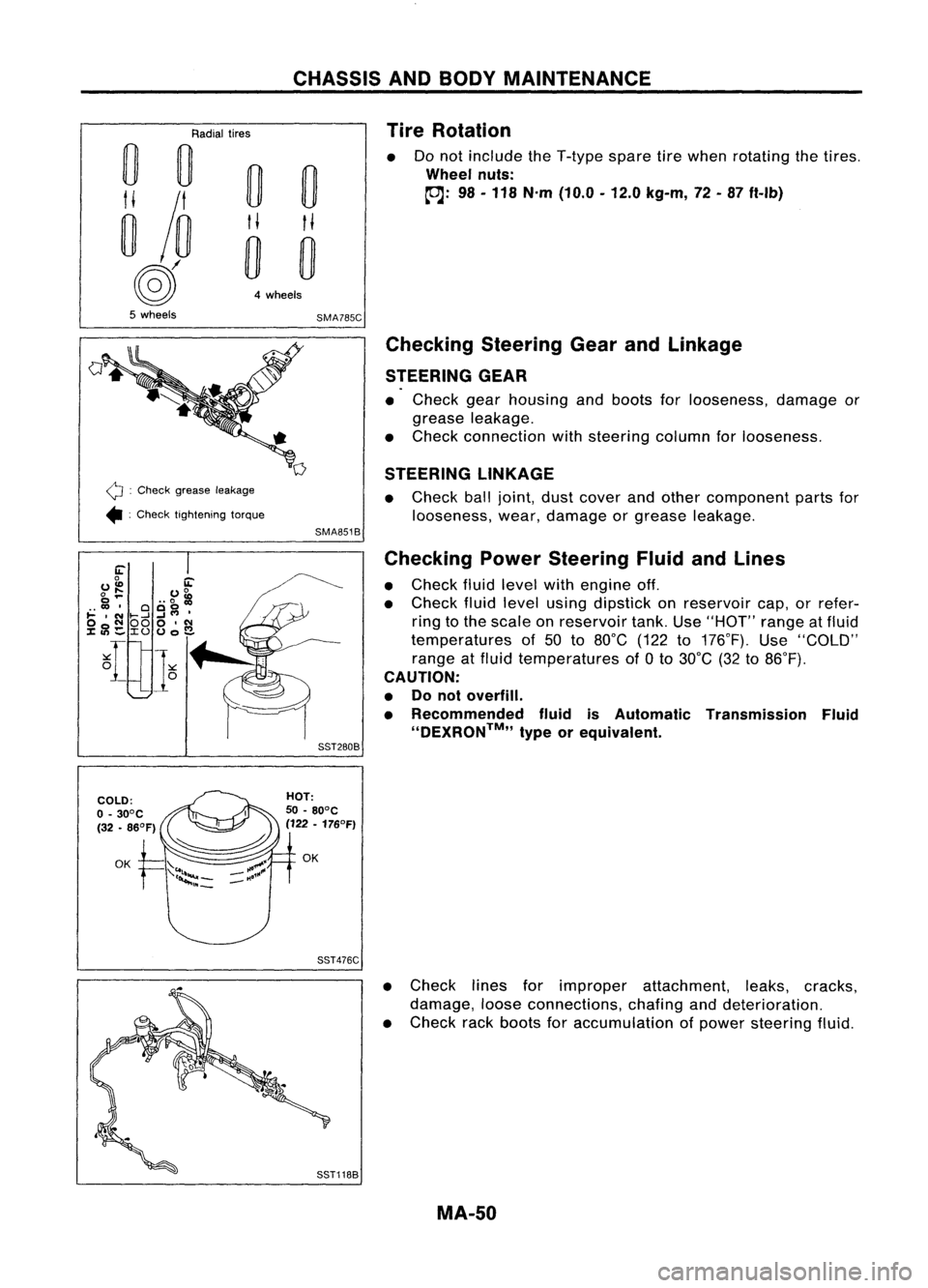
Tire Rotation
Do not include theT-type sparetirewhen rotating thetires .
Wheel nuts:
~: 98-118 N'm (10.0 -12.0 kg-m, 72-87 ft-Ib)
Q :
Check grease leakage
• :Check tightening torque
Checking
SteeringGearandLinkage
STEERING GEAR
• Check gearhousing andboots forlooseness, damageor
grease leakage.
• Check connection withsteering columnforlooseness.
STEERING LINKAGE
• Check balljoint, dustcover andother component partsfor
looseness, wear,damage orgrease leakage.
SMA851B
Checking PowerSteering FluidandLines
• Check fluidlevel withengine off.
• Check fluidlevel using dipstick onreservoir cap,orrefer-
ring tothe scale onreservoir tank.Use"HOT" rangeatfluid
temperatures of50 to80°C (122to176°F). Use"COLD"
range atfluid temperatures of
a
to 30°C (32to86°F).
CAUTION:
• Donot overfill.
• Recommended fluidisAutomatic Transmission Fluid
''DEXRON™,, typeorequivalent.
SST280B
SST476C
•Check linesforimproper attachment, leaks,cracks,
damage, looseconnections, chafinganddeterioration.
• Check rackboots foraccumulation ofpower steering fluid.
MA-50
Page 1610 of 1701
PRECAUTIONSANDPREPARATION
SBR820B Precautions
• When installing eachrubber part,finaltightening mustbe
carried outunder unladen condition* withtires onground.
*:
Fuel, radiator coolantandengine oilfull. Spare tire,jack,
hand tools andmats indesignated positions.
• Use flare nutwrench whenremoving orinstalling brake
tubes.
• After installing removedsuspension parts,check wheel
alignment.
• Donot jack upatthe trailing armandlateral link.
• Always torquebrakelineswhen installing.
Special Service Tools
Tool number
Tool name Description
GG9431 0000
Flare nuttorque
wrench
HT71780000
Spring compressor
ST35652000
Shock absorber
attachment
NT406
NT144
NT145
Removing
andinstalling brakepiping
a:
10
mm
(0.39
in)
Removing andinstalling coilspring
Fixing strutassembly
Tool name
Description
Commercial
ServiceTools
Equivalent to
GG9431 0000
G)
Flare nutcrows
foot
@
Torque wrench Removing
andinstalling brakepiping
NT360
a:
10
mm
(0.39
in)
RA-2
Page 1612 of 1701
SMA525A
SMA113
---I
SRA690A ON-VEHICLE
SERVICE
Rear AxleandRear Suspension Parts
Check axleandsuspension partsforexcessive play,wear or
damage.
• Shake eachrearwheel tocheck forexcessive play.
• Retighten allnuts andbolts tothe specified torque.
Tightening torque:
Refer toREAR SUSPENSION (RA-8).
• Check shockabsorber for
oil
leakage orother damage.
Rear Wheel Bearing
• Check axialendplay.
Axial endplay:
0.05 mm(0.0020 in)orless
• Check thatwheel hubbearings operatesmoothly.
• Check tightening torqueofwheel bearing locknut.
(OJ:
186 •255 N.m (19-26 kg-m, 137•188 ft-Ib)
• Replace wheelbearing assembly ifthere isaxial endplay
or wheel bearing doesnotturn smoothly. RefertoREAR
AXLE -Wheel Hub(RA-6).
RA-4
Page 1614 of 1701
REARAXLE
Wheel Hub
SEC. 430
SRA710A
6
~
186 •255
(19 •26, 137 -188)
Drum
brake
r2'\
Front ~22-29 (2.2 •3.0, 16-22)
Disc
brake
25 -33(2.5 -3.4, 18-25)
~ :N.m (kg-m. ft-Ib)
G)
Spindle
@
Baffle plate
@
Back plate
@
Wheel hubbearing
@
Washer
@
Wheel bearing locknut
(J)
Cotter pin
@
Hubcap
@
ABS sensor
REMOVAL
CAUTION:
• Before removing therear wheel hubassembly, disconnect
the ABS wheel sensor fromtheassembly. Thenmove it
away fromthehub assembly. Failuretodo somay result in
damage tothe sensor wiresandthesensor becoming inop-
erative.
• Wheel hubbearing doesnotrequire maintenance. Ifany of
the following symptoms arenoted, replace wheelhubbear-
ing assembly.
• Growling noiseisemitted fromwheel hubbearing during
operation.
• Wheel hubbearing dragsorturns roughly. Thisoccurs
when turning hubbyhand afterbearing locknutistightened
to specified torque.
RA-6