1995 NISSAN ALMERA N15 radiator
[x] Cancel search: radiatorPage 686 of 1701
FRONTSUSPENSION SYSTEM
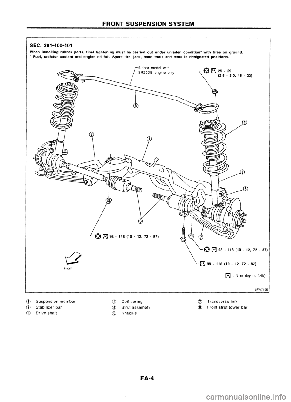
SEC. 391-400-401
When installing rubberparts,finaltightening mustbecarried outunder unladen condition" withtires onground .
• Fuel, radiator coolantandengine oilfull. Spare tire,jack, hand tools andmats indesignated positions.
~~25.29
~ (2.5•3.0, 18•22)
\ \
...
5
~ 98•118 (10•12, 72•87)
Front
to.J:
N. m (kg-m, ft-Ib)
SFA715B
CD
Suspension member
@
Stabilizer bar
@
Drive shaft
@
Coilspring
@
Strut assembly
@
Knuckle
FA-4
(J)
Transverse link
@
Front struttower bar
Page 688 of 1701
ON-VEHICLESERVICE
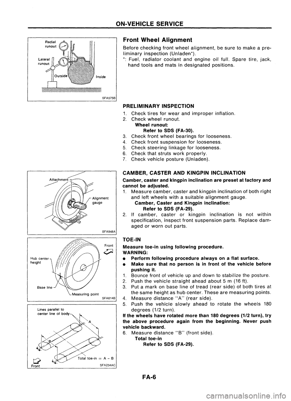
Front Wheel Alignment
Before checking frontwheel alignment, besure tomake apre-
liminary inspection (Unladen*).
*: Fuel, radiator coolantandengine oilfull. Spare tire,jack,
hand tools andmats indesignated positions.
SFA575B PRELIMINARY INSPECTION
1. Check tiresforwear andimproper inflation.
2. Check wheelrunout.
Wheel runout:
Refer toSOS (FA-30).
3. Check frontwheel bearings forlooseness.
4. Check frontsuspension forlooseness.
5. Check steering linkageforlooseness.
6. Check thatstruts workproperly.
7. Check vehicle posture (Unladen).
TOE-IN Measure toe-inusingfollowing procedure.
WARNING:
• Perform following procedure alwaysonaflat surface.
• Make surethatnoperson isin front ofthe vehicle before
pushing it.
1. Bounce frontofvehicle upand down tostabilize theposture.
2. Push thevehicle straight aheadabout5m (16 ft).
3. Put amark onbase lineoftread (rearside) ofboth tires at
the same height ashub center. Thesearemeasuring points.
4. Measure distance"A"(rear side).
5. Push thevehicle slowlyaheadtorotate thewheels 180
degrees (1/2turn).
If the wheels haverotated morethan180degrees
(112
turn), try
the above procedure againfromthebeginning. Neverpush
vehicle backward.
6. Measure distance"B"(front side).
Total toe-in
Refer toSOS (FA-29).
CAMBER,
CASTERANDKINGPIN INCLINATION
Camber, casterandkingpin inclination arepreset atfactory and
cannot beadjusted.
1. Measure camber,casterandkingpin inclination ofboth right
and leftwheels withasuitable alignment gauge.
Camber, CasterandKingpin inclination:
Refer toSOS (FA-29).
2. Ifcamber, casterorkingpin inclination isnot within
specification, inspectfrontsuspension parts.Replace dam-
aged orworn outparts.
Front
SFA948A
SFA614B
SFA234AC
Lines
parallel to
center lineofbody
Q
Front
Hub
center
height
FA-6
Page 706 of 1701
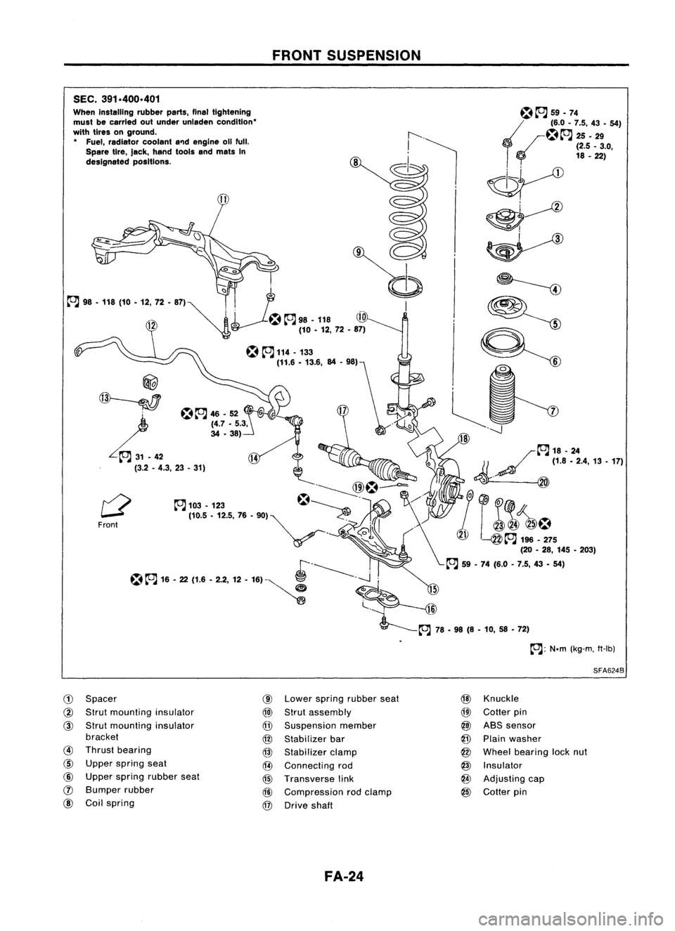
SEC.391.400.401
When installing rubberparts,finaltightening
must becarried outunder unladen condition'
with tires onground.
• Fuel, radiator coolanta'1dengine 011full.
Spare tire,Jack, hand toolsandmats In
designated positions.
@
~
L.~
(3.2-4.3, 23•31)
Front
CD
Spacer
@
Strut mounting insulator
@
Strut mounting insulator
bracket
@
Thrust bearing
@
Upper spring seat
@
Upper spring rubber seat
(J)
Bumper rubber
@
Coilspring
FRONT
SUSPENSION
@
Lower spring rubber seat
@)
Strut assembly
@
Suspension member
@
Stabilizer bar
@
Stabilizer clamp
@
Connecting rod
@
Transverse link
@
Compression rodclamp
@
Drive shaft
FA-24
~~
59.74
~~~.~ ::'.4:9- 54)
o
(2.5_3.0,
18 -22)
~
~~
~ ~
9=:
~~
-----J
/~18-24
1/ ~
(1.8.2.4,13.17)
~. @
&1
(@
~ J~!~5
(20-28, 145 •203)
~ 59•74 (6.0 -7.5, 43•54)
SFA624B
@
Knuckle
@
Cotter pin
@)
ABS sensor
@
Plain washer
@
Wheel bearing locknut
@
Insulator
@
Adjusting cap
@
Cotter pin
Page 711 of 1701
SERVICEDATAANDSPECIFICATIONS (50S)
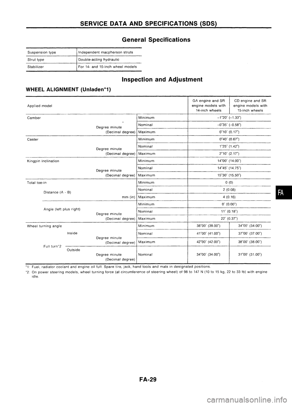
General Specifications
Suspension type
Strut type
Stabilizer Independent
macpherson struts
Double-acting hydraulic
For 14-and 15-inch wheelmodels
Inspection andAdjustment
WHEEL ALIGNMENT (Unladen*1)
GAengine andSR CDengine andSR
Applied model engine
models with enginemodels with
14-inch wheels 15-inchwheels
Camber Minimum
-no'
(-1.33')
.
Degree minute Nominal
-0'35'
(-0.58')
(Decimal degree)Maximum 0'10'
(0.1
r)
Caster Minimum
0'40'(0.6r)
Degree minute Nominal
1
'25' (1.42')
(Decimal degree)Maximum 2'10'
(217")
Kingpin inclination Minimum14'00'
(14.00')
Degree minute Nominal
14'45'
(14.75')
(Decimal degree)Maximum 15'30'
(15.50')
Total toe-in Minimum0(0)
Distance (A-B) Nominal
2(008)
mm (in) Maximum 4(0.16)
Minimum 0'
(0.00')
Angle (leftplus right)
Nominal 11'
(0.18')
Degree minute
(Decimal degree)Maximum 22'
(0.37")
Wheel turning angle Minimum
38'00'
(38.00') 34'00'(34.00')
Inside Nominal4nO'
(41.00')
3rOO'(37.00')
Degree minute
(Decimal degree)Maximum
42'00'
(42.00')
38'00'(38.00')
Full (urn'2
Outside
Degreeminute Nominal 34'00'
(34.00') 31'00'(3100')
(Decimal degree)
'1' Fuel, radiator coolantandengine oilfull. Spare tire,jack, hand tools andmats indesignated positions.
'2: On power steering models,wheelturning force(atcircumference ofsteering wheel)of98 to147 N(10 to15 kg, 22to33 Ib)with engine
idle
FA-29
•
Page 792 of 1701
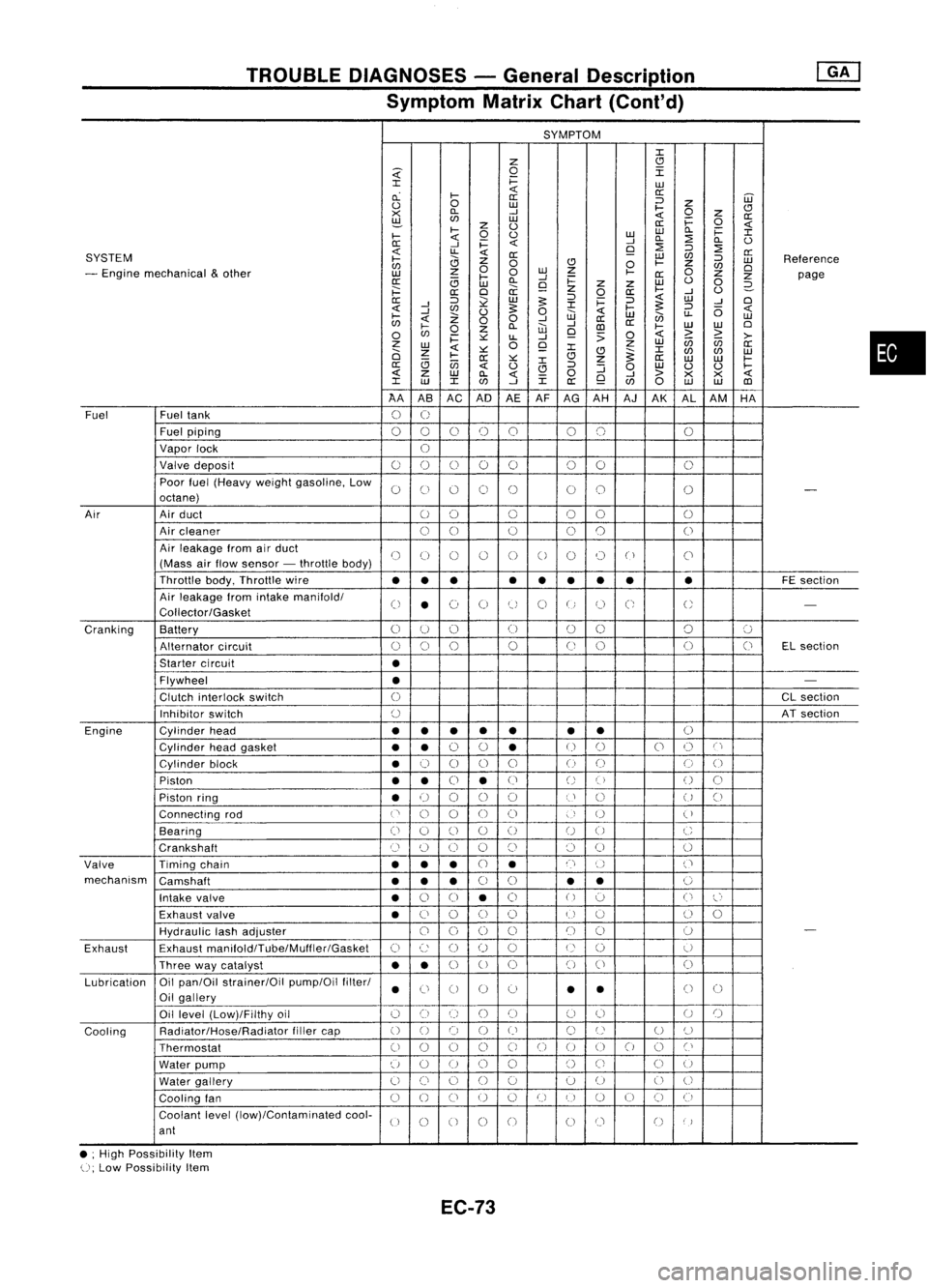
TROUBLEDIAGNOSES -General Description
Symptom MatrixChart(Cont'd)
SYMPTOM
J:
Z
CJ
~
0
I
J:
i=
LU
cL
I-
«
a:
a: ::J
UJ
0
0
LU
I-
Z
CJ
><
D..
-'
«
0
z
a:
~
LU
i=
0
z
0
a:
«
I-
0
0
LULU
D..
i=
J:
I-
«
-'
D..
:2
D..
0
0:
-'
i=
«
9
:2
::J
:2
SYSTEM
«
LL
«
0:
LU
C/J
a:
I-
0
Z
0
CJ
0
I-
Z
::J
LU
Reference
C/J
0
C/J
0
- Engine mechanical
&
other
z
0
LU
Z
I-
0
LU
I-
-'
0:
Z
Z
page
0:
(3
LU
D..
9
i=
z
Z
LU
0
0
2-
;:::
a:
0
a:
z
0
a:
I-
-'
0
0:
::J
~
LU
5:
::J
i=
::J
«
LU
-'
0
-'
J:
5:
«
-'
C/J
0
5:
0
«
I-
::J
(5
«
I-
Z
W
LU
en
LL
LU
C/J
«
00
-'
-'
a:
a:
0
I-
0
Z
D..
W
CD
I-
LU
LU
0
C/J
i=
~
LL
-'
9
:>
0
«
>
~
>-
z
0
Z
LU
(ij
C/J
a:
LU
«
~
9
J:
J:
0
Z
CJ
~
C/J
C/J
LU
I-
0:
~
CJ
Z
a:
LU LU
I-
(3
(jj
J:
a:
«
0
CJ
::J
:J
0
LU
0 0
I-
«
z
LU
D..
«
0
-'
>
><><
«
J:
LU
J:
C/J
-'
J:
a:
9
C/J
0
LU LU
CD
AA ASAC AD
AEAF
AG AH AJAK ALAM HA
Fuel Fueltank
0
U
Fuel piping
00 0
()
0 00 0
Vapor lock
U
Valve deposit
00 000 00
0
Poor fuel(Heavy weightgasoline, Low
0
C)
0 0
()
00
0
-
octane)
Air Airduct
00 0
00
0
Air cleaner
00
0
0
0
0
Air leakage fromairduct
()
(J
()
()
0
0
0 0
("
)
C'
(Mass airflow sensor -throttle body)
Throttle body,Throttle wire
••• •
••
•• •
FE
section
Air leakage fromintake manifold/
0
•
(~)
0
tJ
0
U
C;
U
-
Collector/Gasket
Cranking Battery
0
U
()
(J
00 0
':J
Alternator circuit
()
0
0
0
(J
0 0
(J
ELsection
Starter circuit
•
Flywheel
•
-
Clutch interlock switch
0
CL
section
Inhibitor switch
()
ATsection
Engine Cylinderhead
••
• •
• •
•
()
Cylinder headgasket
••
0
0
•
U
()
0
()
C'
Cylinder block
•
0
0 0
0
()
(J
0
0
Piston
••
0
•
(J
()
()
()
0
Piston ring
•
U
00
0
U
()
U
()
Connecting rod
('
0
0
00
)
U
(
)
Bearing
(i
0
()
0
()
U
0
C
Crankshaft
Cl
(~)
0 0
()
()
0
0
Valve Timingchain
•••
CJ
•
n
()
('
mechanism Camshaft
•••
0
0
•
•
0
Intake valve
•
0
0
•
0
()
':J
0
l~'
Exhaust valve
•
C)
0
()
()
U
u
()
0
HydraUlic lashadjuster
00
0
0
()
()
0
-
Exhaust Exhaust
manifoldlTube/Muffler/Gasket
C)
c:
()
()
0
U
()
U
Three waycatalyst
••
0
U
0 0
()
0
Lubrication Oil
pan/Oil strainer/Oil pump/Oilfilter/
•
Ci
0 0
0
•
•
()
0
Oil gallery
Oil level (Low)/Filthy oil
()
0
()
()()
(J
0
U
()
Cooling Radiator/Hose/Radiator
fillercap
()
0 0
()
()
C)
U
U
()
Thermostat
00
0
0
C)
0
()
00
0
Cl
Water pump
u
0
U
0
0
()
Ci
C)
U
Water gallery
U
()
0
()
0 0
U
0
U
Cooling fan
0
()
CJ
U
0
U
I)
U
()
CJ
(i
Coolant level(low)/Contaminated cool-
U
0
0 0
0
00
()
)
ant
• ;High Possibility Item
U;
Low Possibility Item
EC-73
•
Page 995 of 1701
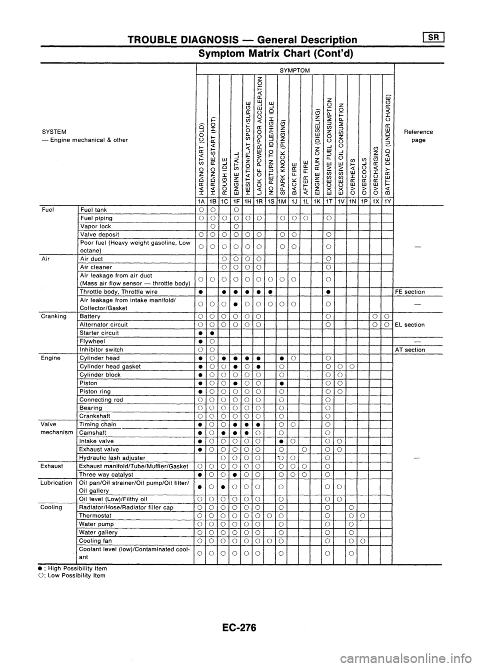
TROUBLEDIAGNOSIS -General Descrip_tio_n
1s_R_1
Symptom MatrixChart(Cont'd)
SYMPTOM
z
0
i=
«
W
a:
z
w
w
w
CJ
CJ
....J
....J
0
Z
a:
w
i=
0
a:
(.)
9
8
«
0.. i=
:I:
::J
(.)
z
:2
i='
en
«
:I:
8
:J
0..
(.)
Q
0
f:::.
CJ
:J
:2
a:
a:
:E
z
w
en
SYSTEM
....J
~
0
0
en
z
:J
w
Reference
0
0..
W
a
w
en
Cl
- Engine mechanical
&
other
I-
en
0
z
0
z
z
S:?-
a: 0..
....J
e-
(.)
0
page
I-
«
l-
ii.
9
~
....J
(.)
2-
a:
~
«
w
0
z
w
CJ
Cl
....J ....J
:.:::
0
:J
....J
Z
«
....J
u.
~
I-
(.)
u..
0
a
«
I-
w
«
Z
0
z
enen
w
en
a:
....J
I-
0..
Z
0
WW
:J
W
W
I-
....J
a:
Cl
0 0
9
en
0
a:
z
a:a:
a:
> >
«
0
«
>-
i=
u..
:J
:.:::
ii:
enen
0
:I:
Z Z
W
0
l-
ii:
w w
a:
Ci Ci
:I:
Z
«
w
:.:::
a:
z
en
en
:I:
(.)
(.)
w
CJ
a
I-
:.:::
a:a:
:.:::
w
a
w
w
a:
a:a:
~
a:
a:
:J
en
(.)
«
(.)
I-
(.)
(.)
w
w
w
« «
0
z
w
«
0
0..
«
u..
Z
x x
>>>
«
:I: :I:
a:
w
:I:
....J
Z
en
(l)
«
w w
w
00 0
(l)
1A 1B
1C 1F1H
1R 1S
1M 1J1L1K
1T
1V
1N
1P1X 1Y
Fuel Fueltank
00 0
Fuel piping
00 0000 000
0
Vapor lock
00
Valve deposit
000 000 00 0
Poor fuel(Heavy weightgasoline. Low
0000 00 00
0
-
octane)
Air Airduct
00 00 0
Air cleaner
0
0
00 0
Air leakage fromairduct
00 00 00 0
0 0
0
(Mass airflow sensor -throttle body)
Throttle body.Throttle wire
•
•
•
•
• •
•
FE
section
Air leakage fromintake
manifoldl
00 0
•
0
0 0
00 0
-
Coliector/Gasket
Cranking Battery
0
0
00 0
0 0
0
0
Alternator circuit
00
00
0
0 0
00
EL
section
Starter circuit
••
Flywheel
•
0
-
Inhibitor switch
00
ATsection
Engine Cylinderhead
•
0
•
•
••
•
0
0
Cylinder headgasket
•
0
()
•
0
•
0
0
00
Cylinder block
•
0
()
0 00 0 00
Piston
•
0
0
•
0
0
•
0
0
Piston ring
•
0
00 0
0 0 00
Connecting rod
00 00
00 0 0
Bearing
000 000 0
0
Crankshaft
00
0 0
0
0 0
0
Valve Timingchain
•
0
0
••
•
0
0 0
mechanism Camshaft
•
0
•• •
0
0 0
Intake valve
•
0
00 0
0
•
0
0
0
Exhaust valve
•
0
00 00 0000
Hydraulic lashadjuster
0000
'0
0 0
-
Exhaust Exhaust
manifoldlTube/Mulfler/Gasket
00
00 0
0
00
0 0
Three waycatalyst
•
0
0
•
0
0 000 0
Lubrication Oilpan/Oil strainer/Oil pump/Oilfilterl
000
0
0 0
0
Oil gallery
••
Oil level (Low)/Filthy oil
00 0000
0 0
0
Cooling Radiator/Hose/Radiator fillercap
00
0 00
0 0 00
Thermostat
00
00 0
0 00 0
00
Water pump
000 000 0 0
0
Water gallery
00 00 00
0 0
0
Cooling fan
00 0
00
0 0
0 0
0
0
Coolant level(low)/Contaminated cool-
00
0000
0 0
0
ant
• ;High Possibility Item
0; Low Possibility Item
EC-276
Page 1139 of 1701
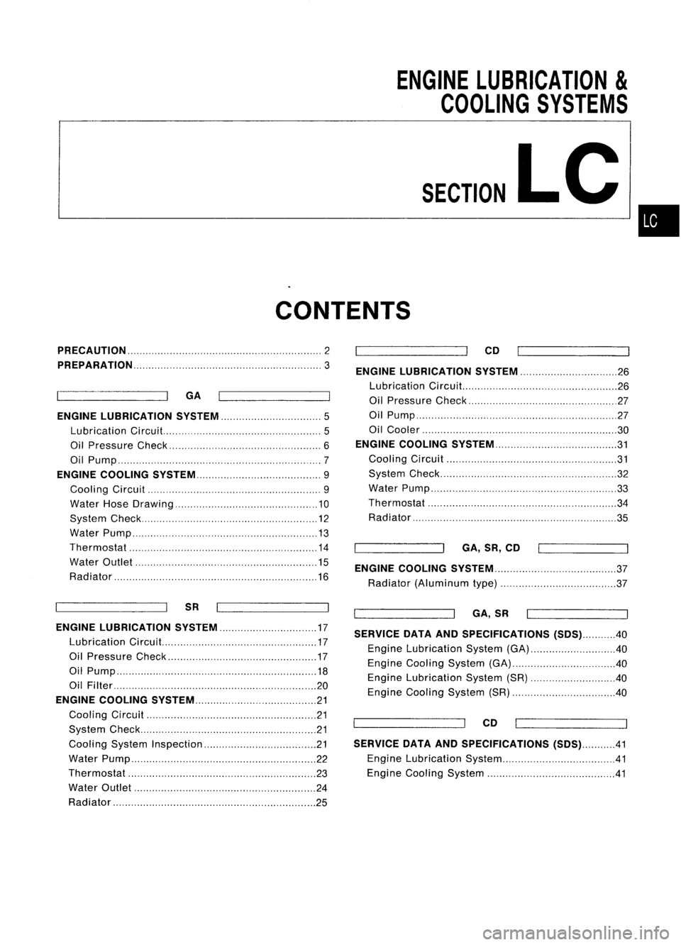
ENGINELUBRICATION
&
COOLING SYSTEMS
SECTION
LC
CONTENTS
•
PRECAUTION
2
PREPARATION
3
GA
ENGINE LUBRICATION SYSTEM
5
Lubrication Circuit.. 5
Oil Pressure Check 6
Oil Pump 7
ENGINE COOLING SySTEM 9
Cooling Circuit 9
Water HoseDrawing 10
System Check 12
Water Pump 13
Thermostat 14
Water Outlet 15
Radiator 16
SR
ENGINE LUBRICATION SYSTEM 17
Lubrication Circuit. 17
Oil Pressure Check 17
Oil Pump 18
Oil FiIter 20
ENGINE COOLING SYSTEM 21
Cooling Circuit 21
System Check 21
Cooling SystemInspection 21
Water Pump 22
Thermostat 23
Water Outlet 24
Radiator 25CO
ENGINE LUBRICATION SYSTEM 26
Lubrication Circuit... 26
Oil Pressure Check 27
Oil Pump ,27
Oil Cooler 30
ENGINE COOLING SYSTEM 31
Cooling Circuit 31
System Check 32
Water Pump ,33
Thermostat 34
Radiator 35
GA,SR,CO
ENGINE COOLING SYSTEM 37
Radiator (Aluminum type) 37
GA,SR
SERVICE DATAANDSPECIFICATIONS (SOS)40
Engine Lubrication System(GA) 40
Engine Cooling System(GA) 40
Engine Lubrication System(SR) 40
Engine Cooling System(SR) 40
CO
SERVICE DATAANDSPECIFICATIONS (SOS)41
Engine Lubrication System .41
Engine Cooling System 41
Page 1142 of 1701
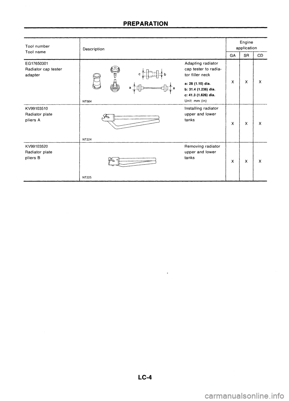
PREPARATION
Engine
Tool number
Description application
Tool name
GASRCD
EG17650301 Adapting
radiator
Radiator captester
~
C~~4b
cap
tester toradia-
adapter
~
tor
filler neck
,
atet? cDJtaa:
28 (1.10) dia.
X
X X
b: 31.4 (1.236) dia.
c: 41.3 (1.626) dia.
NT564
Unit:
mm(in)
KV99103510 Installing
radiator
Radiator plate
~
upper
andlower
pliers A tanks
XX
X
NT224
KV991 03520 Removingradiator
Radiator plate upper
andlower
pliers B
~
tanks
XXX
NT225
LC-4