1995 NISSAN ALMERA N15 fuse box
[x] Cancel search: fuse boxPage 494 of 1701
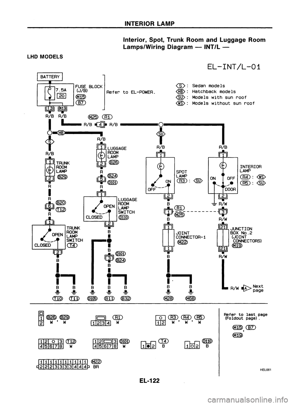
INTERIORLAMP
Interior, Spot,Trunk RoomandLuggage Room
Lamps/Wiring Diagram-INT/L -
LHD MODELS
EL-INT/L-01
FUSE BLOCK
(JIB)
RefertoEL-POWER.
~
@)
@:
Sedanmodels
@:
Hatchback modeIs
@:
Models withsunroof
@:
Models without sunroof
IIT.311
IN;31
RIB RIB
@@)
I
•
RIB
1II1}
RIB
0
I
O~
,
t
t
RIB
i~iLUGGAGE
RIB
RIB
RIB ROOM
m m
1~lrnu~
LAMP
~~
ROOM INTERIOR
LAMP R SPOTLAMP
lbi=Jl~
c!J@}
LAMP
ONOFF
aID:@
1bi=Jl@Q!)
ON
<:BID:
@)
......
R R
OFF.....--
DOOR
I
m
~~
R
LUGGAGE
$@
OPENROOM
B
CBD
=
R/W
LAMP
(ill)
SWITCH
IQP~~i~--------~qpl
R
CLOSED
@llID
c!J
B
R/W
~
rn(!)
JLNCTION
TRUNK
ROOM B
JOINTBOX
No.2
LAMP
•
CONNECTOR-1
(JOINT
SWITCH
•
CONNECTORS)
CLOSED
c::ID
•
~
B
~
m@W
~@)
B
R/W
I
B
I
r.
•
I
I
.
B BB B
B
R/W~Next
-!- -!--!-
-!-
-!-
page
<:ITID
(ill)
(Ql05)
~
@
~~
~CID
~W
wCBID(@@
rn::g]
W'W'W
~~~
~ W
I
W
I:illliTI]
@
~W
fHiI'
II~@W
4567B W
rh-f:l@
~ B
n.o-r:l@llID
LUQ.LgJ
B
Refer
tolast page
(Foldout page).
ITIillIITillIII
~BR
EL-122 HEL061
Page 524 of 1701
WARNINGLAMPSANDBUZZER
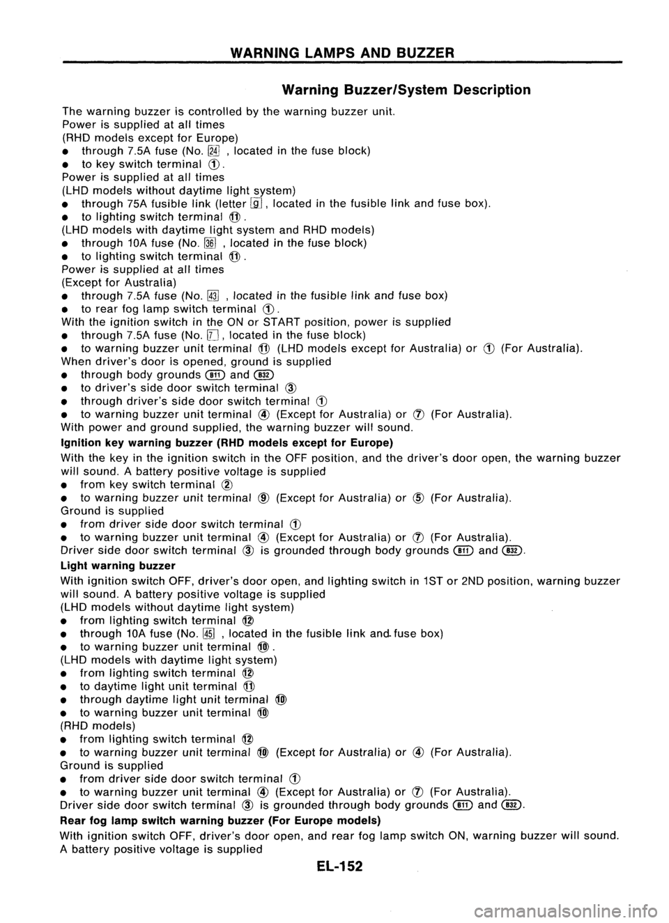
Warning Buzzer/System Description
The warning buzzeriscontrolled bythe warning buzzerunit.
Power issupplied atall times
(RHD models exceptforEurope)
• through 7.5Afuse (No.
[fA],
located inthe fuse block)
• tokey switch terminal
CD.
Power issupplied atall times
(LHD models withoutdaytime lightsystem)
• through 75Afusible link(letter
[.9J,
located inthe fusible linkand fuse box).
• tolighting switchterminal
@.
(LHD models withdaytime lightsystem andRHD models)
• through 10Afuse (No.
~J,
located inthe fuse block)
• tolighting switchterminal
@.
Power issupplied atall times
(Except forAustralia)
• through 7.5Afuse (No.~,located inthe fusible linkand fuse box)
• torear foglamp switch terminal
CD.
With theignition switchinthe ONorSTART position, powerissupplied
• through 7.5Afuse (No.
11J,
located inthe fuse block)
• towarning buzzerunitterminal
@
(LHD models exceptforAustralia) or
CD
(For Australia).
When driver's doorisopened, groundissupplied
• through bodygrounds
@
and
@
• todriver's sidedoor switch terminal
@
• through driver'ssidedoor switch terminal
G)
• towarning buzzerunitterminal
@
(Except forAustralia) or
(J)
(For Australia).
With power andground supplied, thewarning buzzerwillsound.
Ignition keywarning buzzer(RHOmodels exceptforEurope)
With thekey inthe ignition switchinthe OFF position, andthedriver's dooropen, thewarning buzzer
will sound. Abattery positive voltageissupplied
• from keyswitch terminal
CID
• towarning buzzerunitterminal
CID
(Except forAustralia) or
@)
(For Australia).
Ground issupplied
• from driver sidedoor switch terminal
G)
• towarning buzzerunitterminal
@
(Except forAustralia) or
(J)
(For Australia).
Driver sidedoor switch terminal
@
isgrounded throughbodygrounds
@
and
@.
Light warning buzzer
With ignition switchOFF,driver's dooropen, andlighting switchin1ST or2ND position, warningbuzzer
will sound. Abattery positive voltageissupplied
(LHD models withoutdaytime lightsystem)
• from lighting switchterminal
@
• through 10Afuse (No.
@ID,
located inthe fusible linkand. fuse box)
• towarning buzzerunitterminal
@>.
(LHD models withdaytime lightsystem)
• from lighting switchterminal
@
• todaytime lightunitterminal
@
• through daytime lightunitterminal
@>
• towarning buzzerunitterminal
@>
(RHD models)
• from lighting switchterminal
@
• towarning buzzerunitterminal
@>
(Except forAustralia) or
@
(For Australia).
Ground issupplied
• from driver sidedoor switch terminal
G)
• towarning buzzerunitterminal
@
(Except forAustralia) or
(J)
(For Australia).
Driver sidedoor switch terminal
@
isgrounded throughbodygrounds
(!ill
and
@.
Rear foglamp switch warning buzzer(ForEurope models)
With ignition switchOFF,driver's dooropen, andrear foglamp switch ON,warning buzzerwillsound.
A battery positive voltageissupplied
EL-152
Page 526 of 1701
![NISSAN ALMERA N15 1995 Service Manual WARNINGLAMPSANDBUZZER
Warning Buzzer/Wiring Diagram-BUZZER -
LHD MODELS
EL-BUZZER-01
DOOR
SWITCH
DRIVER'S
SIDE
(]ID
OPEN
Refer
to
EL-POWER.
CLOSED
IJ:i=n
B
•
f.
B B
~ ~
@ll)@
FUSE
BL NISSAN ALMERA N15 1995 Service Manual WARNINGLAMPSANDBUZZER
Warning Buzzer/Wiring Diagram-BUZZER -
LHD MODELS
EL-BUZZER-01
DOOR
SWITCH
DRIVER'S
SIDE
(]ID
OPEN
Refer
to
EL-POWER.
CLOSED
IJ:i=n
B
•
f.
B B
~ ~
@ll)@
FUSE
BL](/manual-img/5/57349/w960_57349-525.png)
WARNINGLAMPSANDBUZZER
Warning Buzzer/Wiring Diagram-BUZZER -
LHD MODELS
EL-BUZZER-01
DOOR
SWITCH
DRIVER'S
SIDE
(]ID
OPEN
Refer
to
EL-POWER.
CLOSED
IJ:i=n
B
•
f.
B B
~ ~
@ll)@
FUSE
BLOCK
(JIB)
~
m
IN~41
@:
Withdaytime lightsystem
G1@:WithoutdaytimelightsYstem
*1".@B/R @W
,
G *2...
@
RIL @W/R
•
~ *3".@R/B @R/Y
1I1DI •
IGN WARNING
SW BUZZER
RR FOG DOORUNIT
SW SW(DR)
@
lbjdJ ~
PU/R R
[ttl ']'t4IJUNCTION
BOX NO.2
(JOINT
CONNECTORS)
~------1I~41
PU/R
t
~@)
m
REAR
[jJ
(]V
IND FOG R
LAMP ~
SWITCH II1II
~
OFF
7.5A
1431
B/R
rm
TAIL/L FUSE
I!JjJJ
*2
I
O~ DL W/R
[iJt~:1
R/Y
t
I_-.I~o
tt
RIB
Ii1'on
TAILIL
OUTPUT
RIL
will
TAILIL
SW
\bj::tl
B
rn~
I
JOINT
CONNECTOR-3
I
lU ....,
DAYTIME
=jF
I
LIGHT B
UNIT BB
I..-.--
---J~~
I
BATTERY
I
•
~-17-5A-~'
10.
m
1361
W B/R P
!
I.-",
1$1
~~1)
*1 P
will
L
LIGHTING
SWITCH
~
~~
~BR
IIITIillIIITIIT
@
~BR
~~@)
56j8191OU12 W
r1TmCW
TIT'
B
Refer
tolast page
(Foldout page).
(BID ~
•
~ (106)
•
~~
~GY
HEL083
EL-154
Page 552 of 1701
![NISSAN ALMERA N15 1995 Service Manual POWERWINDOW
System Description
Power issupplied atall times
• from 25Afusible link(Letter
IT],
located inthe fusible linkand fuse box)
• tocircuit breaker terminal
CD
• through circuitbreak NISSAN ALMERA N15 1995 Service Manual POWERWINDOW
System Description
Power issupplied atall times
• from 25Afusible link(Letter
IT],
located inthe fusible linkand fuse box)
• tocircuit breaker terminal
CD
• through circuitbreak](/manual-img/5/57349/w960_57349-551.png)
POWERWINDOW
System Description
Power issupplied atall times
• from 25Afusible link(Letter
IT],
located inthe fusible linkand fuse box)
• tocircuit breaker terminal
CD
• through circuitbreaker terminal @
• topower window relayterminal
CID.
With ignition switchinON orSTART position, powerissupplied
• through 7.5Afuse (No.l2I located inthe fuse block)
• topower window relayterminal
CD.
Ground issupplied topower window relayterminal @
• through bodygrounds
@,
@D
and@D.
The power window relayisenergized andpower issupplied
• through powerwindow relayterminal
• topower window mainswitch terminals
CD
and @,
• topassenger sidepower window sub-switch terminals
CID
and @,
• torear power window sub-switch LHterminal @
>
• torear power window sub-switch RHterminal @.
MANUAL OPERATION
Driver's door
Ground issupplied
• tofront power window mainswitch terminals
CID
and @
• through bodygrounds
@,
@Dand
@!D.
WINDOW UP
When adriver sideswitch inthe power window mainswitch ispressed inthe upposition,
power issupplied
• todriver sidepower window regulator terminal@
• through powerwindow mainswitch terminal
em.
Ground issupplied
• todriver sidepower window regulator terminal
CD
• through powerwindow mainswitch terminal
cID.
Then, themotor raises thewindow untiltheswitch isreleased.
WINDOW DOWN
When adriver sideswitch inthe power window mainswitch ispressed inthe down position,
power issupplied
• todriver sidepower window regulator terminal
('t'
• through powerwindow mainswitch terminal
cID.
Ground issupplied
• todriver sidepower window regulator terminal~)
• through powerwindow mainswitch terminal
em.
Then, themotor lowers thewindow untiltheswitch isreleas.ed.
Except dr'ver's door
Ground issupplied
• topower window mainswitch terminal
CID
• through bodygrounds
@,
@Dand@D.
PASSENGER'S DOOR
NOTE:
Figures inparentheses ()refer toterminal Nos.arranged inorder whentheUPorDOWN section of
power window switchispressed.
Operation bymain switch
Power issupplied
• through powerwindow mainswitch
(CID,
@)
• topassenger sidepower window sub-switch (@,
CID).
El-180
Page 569 of 1701
POWERWINDOW
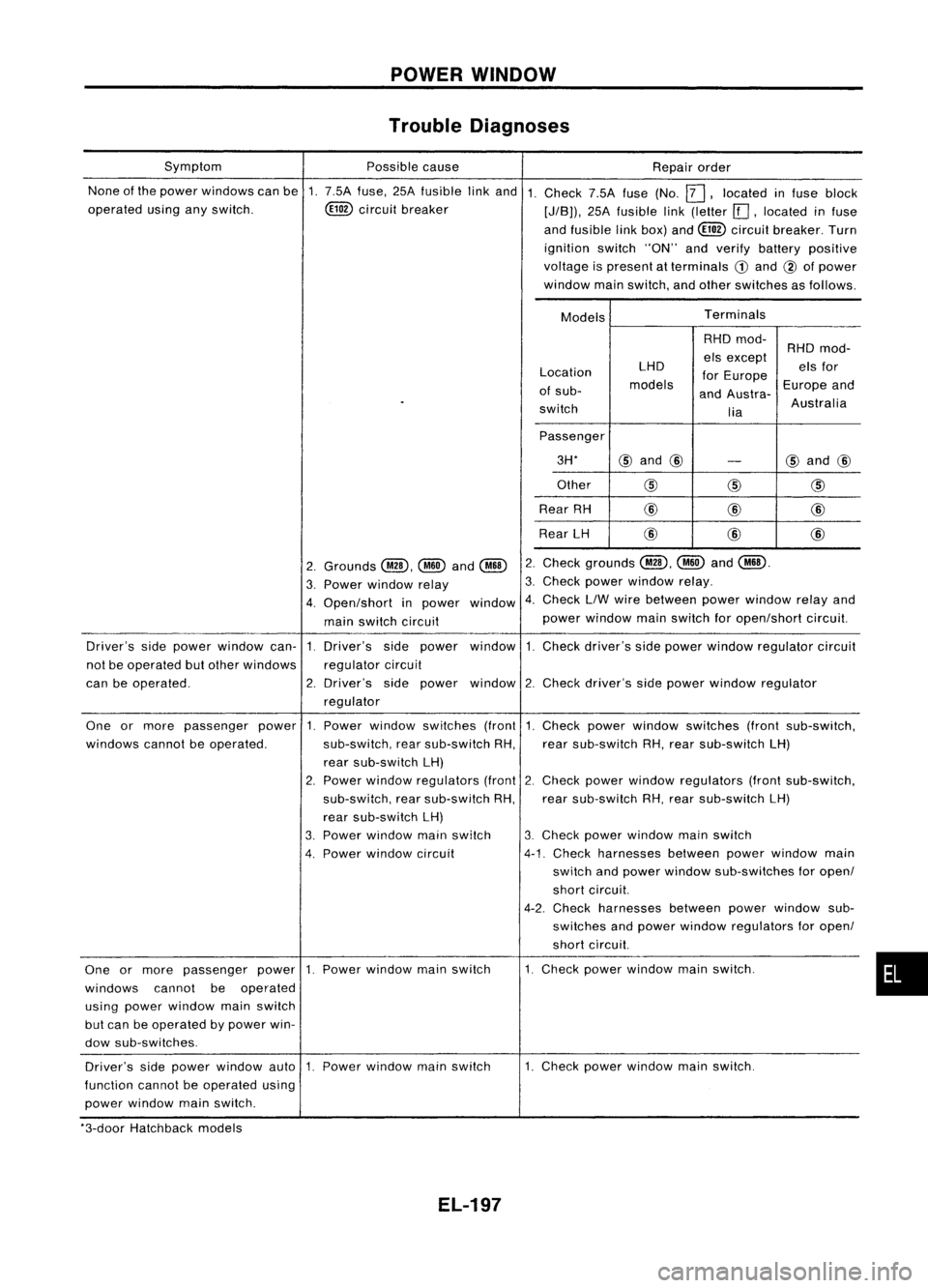
Trouble Diagnoses
None ofthe power windows canbe1.7.5A fuse, 25Afusible linkand 1.
operated usinganyswitch. ~circuit breaker
Symptom
Possiblecause
Repairorder
Check 7.5Afuse(No.
12J,
located infuse block
[J/B)), 25Afusible link(letter [[],located infuse
and fusible linkbox) and~ circuit breaker. Turn
ignition switch"ON"andverify battery positive
voltage ispresent atterminals
CD
and @ofpower
window mainswitch, andother switches asfollows.
Models Terminals
Location
of sub-
switch LHD
models RHD
mod-
els except
for Europe
and Austra-
lia RHD
mod-
els for
Europe and
Australia
Passenger 3H*
@
and @
-
@
and @
Other
@@
@
Rear RH @
@
@
Rear LH @
@@
Check grounds
@,~
and
@ill.
Check powerwindow relay.
Check LlWwire between powerwindow relayand
power window mainswitch foropen/short circuit.
2.
3.
window 4.
2.
Grounds
@,~
and
@ill
3. Power window relay
4. Open/short inpower
main switch circuit
Driver's sidepower window can-1.Driver's sidepower window 1.Check driver's sidepower window regulator circuit
not beoperated butother windows regulatorcircuit
can beoperated. 2.Driver's sidepower window 2.Check driver's sidepower window regulator
regulator
•
1.
Check powerwindow switches (frontsub-switch,
rear sub-switch RH,rear sub-switch LH)
2. Check power window regulators (frontsub-switch,
rear sub-switch RH,rear sub-switch LH)
3. Check powerwindow mainswitch
4-1. Check harnesses betweenpowerwindow main
switch andpower window sub-switches foropen/
short circuit.
4-2. Check harnesses betweenpowerwindow sub-
switches andpower window regulators foropen/
short circuit.
1. Check powerwindow mainswitch.
Power
window switches (front
sub-switch, rearsub-switch RH,
rear sub-switch LH)
2. Power window regulators (front
sub-switch, rearsub-switch RH,
rear sub-switch LH)
3. Power window mainswitch
4. Power window circuit
One
ormore passenger power1.
windows cannotbeoperated.
One ormore passenger power1.Power window mainswitch
windows cannotbeoperated
using power window mainswitch
but can beoperated bypower win-
dow sub-switches.
Driver's sidepower window auto1.Power window mainswitch
function cannotbeoperated using
power window mainswitch. 1.
Check powerwindow mainswitch.
*3-door Hatchback models
EL-197
Page 570 of 1701
POWERDOORLOCK
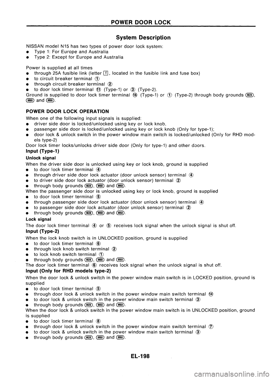
System Description
NISSAN modelN15hastwotypes ofpower doorlocksystem:
• Type 1:For Europe andAustralia
• Type 2:Except forEurope andAustralia
Power issupplied atall times
• through 25Afusible link(letter
OJ,
located inthe fusible linkand fuse box)
• tocircuit breaker terminal
(!)
• through circuitbreaker terminal
@
• todoor locktimer terminal
@
(Type-1) or
CID
(Type-2).
Ground issupplied todoor locktimer terminal
@
(Type-1) or
(!)
(Type-2) throughbodygrounds @D,
@ID
and
@D.
POWER DOORLOCKOPERATION
When oneofthe following inputsignals issupplied:
• driver sidedoor islocked/unlocked usingkeyorlock knob,
• passenger sidedoor islocked/unlocked usingkeyorlock knob (Only fortype-1);
• door lock
&
unlock switchinthe power window mainswitch islocked/unlocked (OnlyforRHD mod-
els type-2)
Door locktimer locks/unlocks driversidedoor (Only fortype-1) andother doors.
Input (Type-1)
Unlock signal
When thedriver sidedoor isunlocked usingkeyorlock knob, ground issupplied
• todoor locktimer terminal
@
• through driversidedoor lockactuator (doorunlock sensor) terminal
@
• todriver sidedoor lockactuator (doorunlock sensor) terminal
@
• through bodygrounds @D,
@ID
and
@D.
When thepassenger sidedoor isunlocked usingkeyorlock knob, ground issupplied
• todoor locktimer terminal
CID
• through passenger sidedoor lockactuator (doorunlock sensor) terminal
@
• topassenger sidedoor lockactuator (doorunlock sensor) terminal
@
• through bodygrounds @D,
@ID
and@D.
Lock signal
The door locktimer terminal
@
or
@
receives locksignal whentheunlock signalisshut off.
Input (Type-2)
When thelock knob switch isin UNLOCKED position,groundissupplied
• todoor locktimer terminal
CID
• through lockknob switch terminal
@
• tolock knob switch terminal
(!)
• through bodygrounds @D,
@ID
and
@ill.
The door locktimer terminal
CID
receives locksignal whentheunlock signalisshut off.
Input (Only forRHO models type-2)
When thedoor lock
&
unlock switch inthe power window mainswitch isin LOCKED position,groundis
supplied
• todoor locktimer terminal
CID
• through doorlock
&
unlock switchinthe power window mainswitch terminal
@
• todoor lock
&
unlock switch inthe power window mainswitch terminal
CID
• through bodygrounds @D,
@@
and
@ill.
When thedoor lock
&
unlock switchinthe power window mainswitch isin UNLOCKED position,ground
is supplied
• todoor locktimer terminal
@
• through doorlock
&
unlock switchinthe power window mainswitch terminal
(J)
• todoor lock
&
unlock switchinthe power window mainswitch terminal
CID
• through bodygrounds @D,
@@
and
@ill.
EL-198
Page 604 of 1701
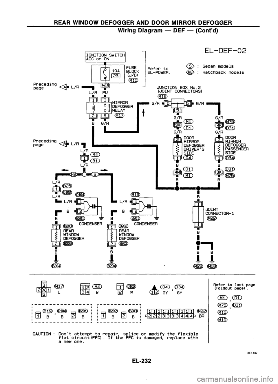
REARWINDOW DEFOGGER ANDDOOR MIRROR DEFOGGER
Wiring Diagram -DEF -(Cont'd)
JUNCTION BOXNo.2
(JOINT CONNECTORS)
G/R?G/R-'
EL-DEF-02
Sedan models
Hatchback models
@:
@:
G/R
IUT\
G/RIG=7c:\
~\.Mi.J ~~
1~1
([D
I~l
@)
G/R G/R
(J)
~RAOA
m~~~
DEFOGGER
DEFOGGER
DRIVER'S PASSENGER
SIDE SIDE
ClJC@ ClJ@)
B B
IrtJl ~~~ ~ 1$1~~~
B B
____ I&__
le__ '
•
B
(1J
1
JOINT
CONNECTOR-1
~
~ B
I
"
a
a
!- !-
~~
Refer
to
EL-POWER.
t
FUSE
BLOCK
(JIB)
~
Preceding ~L/R
1~31
page ~.....
L/R PU
I
1
1
1~IIMrRAOA
n
DEFOGGER
U
RELAY
Ibi=U ~
@)
B
G/R
I
Preceding ~L/R
page ~,
L/R
IU'7"\
~0:M.I
ICIJI(]I)
L/R
..... I~...
~O
~S:-"
L/R
ctI@
~
1619'
L/R ~
IE!.!3I
... L/R ~ L/R~
r- B~1 r-B~1
B ~
=
B
@QD -
m ~
~NSER
I:j:'l ~
CO~SER
REAR REAR
WINDOW WINDOW
DEFOGGER DEFOGGER
IbjJ ~
Ibi=JI~
B B
-!
!-
~ ~
r---------------, ~-----------,
I II I
I ~ ~ ~II ~ ~I
ITIIIII.TIII:TI ~
:[jjB'B (gjB::rTIB @lB:~BR
I II I
L
~~ ~
+
2 1 L
5
FmlaID
001
W
.C@,~
Refer
tolast page
(Fo ldout page).
CBD
(ill)
,
~@
~
CAUTION: Don'tattempt torepair. spliceormodify theflexible
flat circuit (FFC).
If
the FFC isdamaged, replacewith
a new one.
HEL137
EL-232
Page 621 of 1701
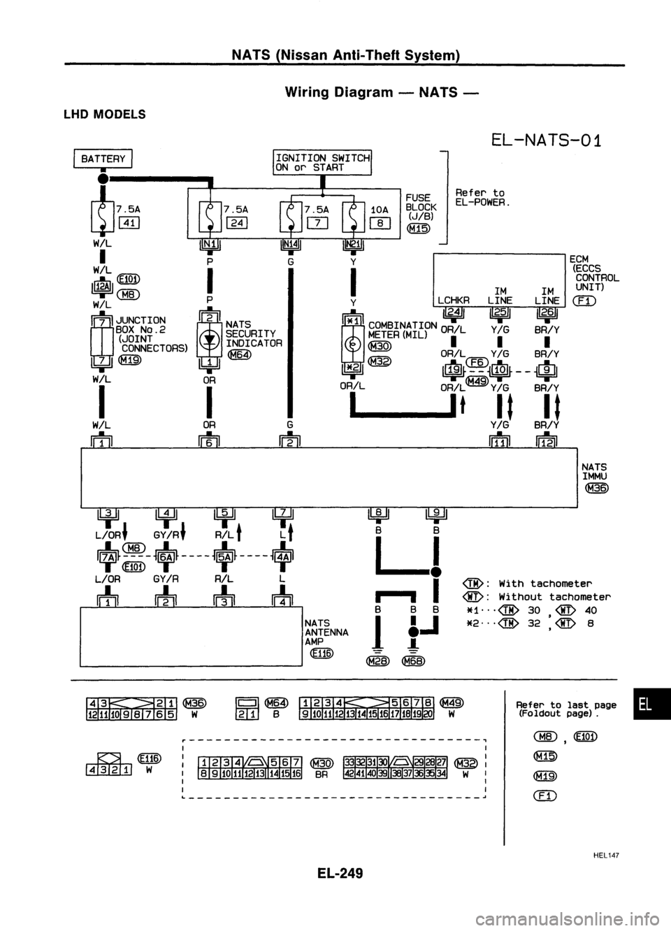
NATS(Nissan Anti-Theft System)
Wiring Diagram -NATS -
LHD MODELS
EL-NATS-01
ECM(ECCSCONTROL
UNIT)
em
Refer
to
EL-POWER.
FUSE
BLOCK
(JIB)
~
1M1M
Y LCHKRLINELINE
!i*1ll
"2.4/
I~ I 1/
2•6
11
i
COMBINATION ORILY
IG
BR/Y
M~~ER(MIL)
II I
~ OR/L
Y/G
BR/Y
11*.21 ~ It~~4~~~$~--
~Ifll
OR/L OR/L
Y/G
BR/Y
1 __
lt
It It
Y/G
BR/Y
IiTIil
IDil
G
m
OR
m
I
BATTERY
I
•
l75A
~WJ
W/L
I
WIL
~(fI@
~
rn;
I
JUNCTION
BOX
NO.2
(JOINT
CONNECTORS)
~
I
WIL
rn
NATSIMMU
~
~ lifll
U:¥~
L/OR' GY
IR'
R/L
t
L
t
~~-~~~----~~~----~
L/OR GY
IR
R/L L
m
wh
rrh
m
NATSANTENNA
AMP
~
~
B B
LJ
..
,- .., I
B BB
1
f.J
~~
@:
With tachometer
@:
Without tachometer
*1",@ 30
@
40
•
*2",@ 32
@
8
,
&~~
1211JOSIV 65 W
Refer
tolast page •
(Foldout page).
~WID
~W
r---------------------------------~
L ~
,
~
@])
em
HEL147
EL-249