1995 NISSAN ALMERA N15 fuse box
[x] Cancel search: fuse boxPage 973 of 1701
ON-BOARDDIAGNOSTIC SYSTEMDESCRIPTION
for CONSULT
t======/
NISSANCONSULT EE940
+
I
~
I
START
I
SUB
MODE
I
SEF253Q CONSULT
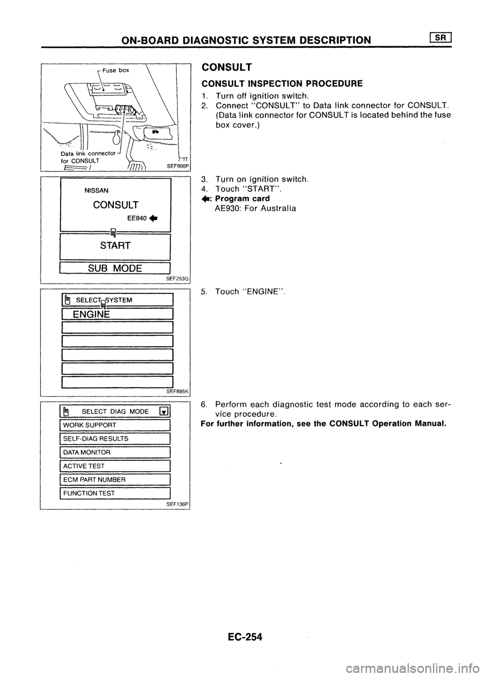
CONSULT INSPECTION PROCEDURE
1. Turn offignition switch.
2. Connect "CONSULT" toData linkconnector forCONSULT.
(Data linkconnector forCONSULT islocated behindthefuse
box cover.)
3. Turn onignition switch.
4. Touch "START".
+:
Program card
AE930: ForAustralia
5. Touch "ENGINE",
~ SELECT~S=Y=S=TE=M====
ENGINE
SEF895K
~ SELECT DIAGMODE
[i]
WORK SUPPORT
SELF-DIAG RESULTS
DATA MONITOR
ACTIVE TEST
ECM PART NUMBER
FUNCTION TEST
SEF136P
6.
Perform eachdiagnostic testmode according toeach ser-
vice procedure.
For further information, seetheCONSULT Operation Manual.
EC-254
Page 1133 of 1701
TROUBLEDIAGNOSES
Air Conditioner CutControl (Cont'd)
LHD models
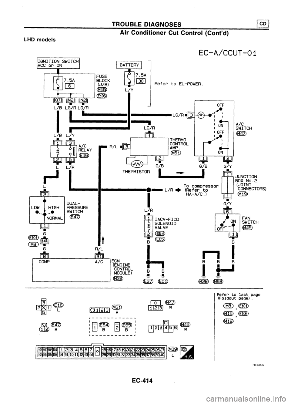
EC-A/CCUT-01
Refer toEL-POWEA.
OFF
LG/R~
I
,
I
I
ON
A/C
LG/R
I
SWITCH
m
I
OFF
@
I
THERMO
CONTROL
AMP.
~
ON
L/Y
~ ~
G/B G/BG/Y
THERMISTOR
I I
m
._-~--_. rn
JUNCTION
BOX
NO.2
To compressor (JOINT
._ L/R. (Referto CONNECTORS)
I
HA-A/C.)~~
G/Y
00
~E~N~~gD
I?iJ
~~~TCH
VALVE OFF--~
IkjJ
(E64) ~
B (E65) B
I
r1
I
• .., BBB
1 ~
1
i....l
mm ~~
RIL
~
t
FUSE
BLOCK
(JIB)
~
(BOO)
R/L
IriDl
A/C
DUAL-
PRESSURE SWITCH
~
1~11I~211~1
LIB LG/R LG/R
II-~ --
LIB
L/Y
IT ~IA/C
n
RELAY
U
UID
4=JJ~
L L/R
~L
rn
I
ECM(ENGINECONTROLMODULE)
---------- @
n
LOW HIGH
... ~~_.
NORMAL
I!4Jl
G
~~1;1$1
G
m
COMP
~(E16)
T
L
JS4.ffi
(tiS)
B
~-----------.,
I I
:ITl~ ~~:
I I
L
~
IQl@
~ W
Refer
tolast page
(Foldout page).
CMID
(El0n
,
lf1@
(E106)
,
~
HEC095
EC-414
Page 1365 of 1701
HOWTOREAD WIRING DIAGRAMS
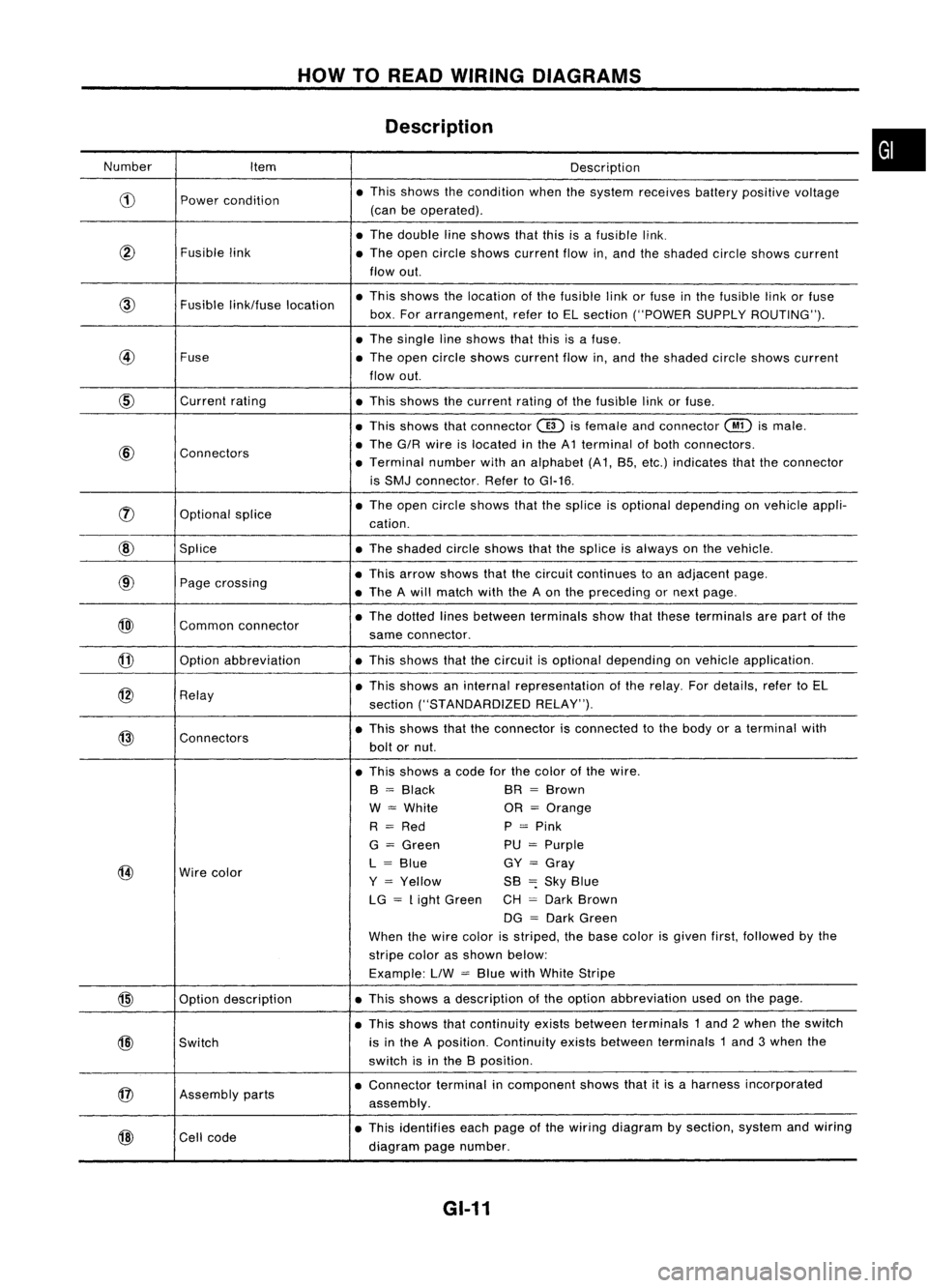
Description
Number Item Description
CD
Power
condition •
This shows thecondition whenthesystem receives batterypositive voltage
(can beoperated) .
• The double lineshows thatthisisafusible link.
@
Fusiblelink
•The open circle shows current flowin,and theshaded circleshows current
flow out.
link/fuse location •
This shows thelocation ofthe fusible linkorfuse inthe fusible linkorfuse
box. Forarrangement, refertoEL section ("POWER SUPPLYROUTING") .
• The single lineshows thatthisisafuse.
@
Fuse
•The open circle shows current flowin,and theshaded circleshows current
flow out.
CID
Current
rating
•This shows thecurrent ratingofthe fusible linkorfuse .
• This shows thatconnector
@)
isfemale andconnector
@
ismale .
@
Connectors •
The G/R wire islocated inthe A1 terminal ofboth connectors.
• Terminal numberwithanalphabet (A1, B5, etc.) indicates thattheconnector
is SMJ connector. RefertoGI-16 .
rJ)
Optionalsplice •
The open circle shows thatthesplice isoptional depending onvehicle appli-
cation.
@
Splice •The shaded circleshows thatthesplice isalways onthe vehicle.
@
Page
crossing •
This arrow shows thatthecircuit continues toan adjacent page.
• The Awill match withtheAon the preceding ornext page .
@)
Commonconnector •
The dotted linesbetween terminals showthatthese terminals arepart ofthe
same connector.
@
Option
abbreviation •This shows thatthecircuit isoptional depending onvehicle application.
@
Relay •
This shows aninternal representation ofthe relay. Fordetails, refertoEL
section ("STANDARDIZED RELAY").
@
Connectors •
This shows thattheconnector isconnected tothe body oraterminal with
bolt ornut.
• This shows acode forthe color ofthe wire.
B
=
Black BR
=
Brown
W
=
White OR
=
Orange
R
=
Red P
=
Pink
G
=
Green PU
=
Purple
@
Wire
color L
=
Blue GY
=
Gray
Y
=
Yellow SB
=:
Sky Blue
LG
=
Light Green CH
=
Dark Brown
DG
=
Dark Green
When thewire color isstriped, thebase color isgiven first,followed bythe
stripe colorasshown below:
Example: LlW
=
Blue withWhite Stripe
@
Optiondescription •
This shows adescription ofthe option abbreviation usedonthe page.
• This shows thatcontinuity existsbetween terminals 1and 2when theswitch
@)
Switch is
inthe Aposition. Continuity existsbetween terminals 1and 3when the
switch isinthe Bposition .
@
Assembly
parts •
Connector terminalincomponent showsthatitis aharness incorporated
assembly .
@
Cell
code •
This identifies eachpage ofthe wiring diagram bysection, systemandwiring
diagram pagenumber.
GI-11
•
Page 1366 of 1701
HOWTOREAD WIRING DIAGRAMS
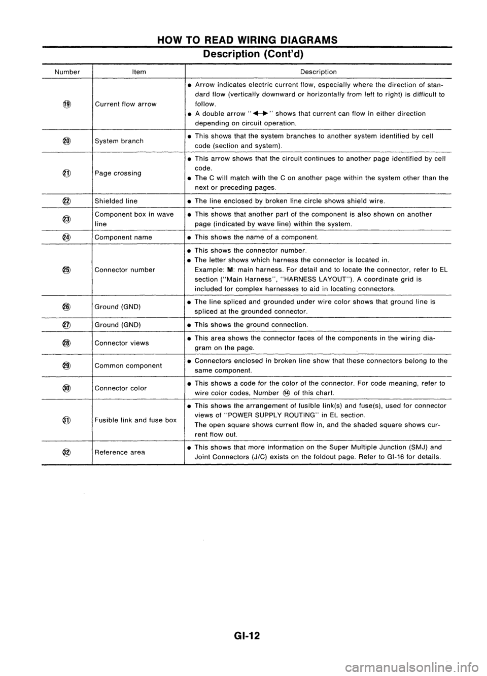
Description (Cont'd)
Number Item Description
• Arrow indicates electriccurrentflow,especially wherethedirection ofstan-
dard flow(vertically downward orhorizontally fromlefttoright) isdifficult to
@)
Current
flowarrow follow.
• Adouble arrow" ...."shows thatcurrent canflow ineither direction
depending oncircuit operation .
@)
System
branch •
This shows thatthesystem branches toanother systemidentified bycell
code (section andsystem) .
• This arrow shows thatthecircuit continues toanother pageidentified bycell
@
code.
Page crossing
•The Cwill match withtheCon another pagewithin thesystem otherthanthe
next orpreceding pages.
@
Shieldedline •
The lineenclosed bybroken linecircle shows shieldwire.
@)
Component
boxinwave •
This shows thatanother partofthe component isalso shown onanother
line page
(indicated bywave line)within thesystem.
@
Component
name •This shows thename ofacomponent.
• This shows theconnector number.
• The letter shows whichharness theconnector islocated in.
@)
Connector
number Example:
M:main harness. Fordetail andtolocate theconnector, refertoEL
section ("MainHarness", "HARNESS LAYOUT").Acoordinate gridis
included forcomplex harnesses toaid inlocating connectors .
@
Ground
(GND) •
The linespliced andgrounded underwirecolor shows thatground lineis
spliced atthe grounded connector.
@
Ground
(GND) •
This shows theground connection.
@)
Connector
views •
This area shows theconnector facesofthe components inthe wiring dia-
gram onthe page .
@)
Common
component •
Connectors enclosedinbroken lineshow thatthese connectors belongtothe
same component.
@l
Connector
color •
This shows acode forthe color ofthe connector. Forcode meaning, referto
wire color codes, Number
@
ofthis chart.
• This shows thearrangement offusible link(s)andfuse(s), usedforconnector
@
views
of"POWER SUPPLYROUTING" inEL section.
Fusible linkand fuse box
Theopen square showscurrent flowin,and theshaded squareshowscur-
rent flow out.
@
Reference
area •
This shows thatmore information onthe Super Multiple Junction (SMJ)and
Joint Connectors
(J/C)
exists onthe foldout page.RefertoGI-16 fordetails.
GI-12
Page 1491 of 1701
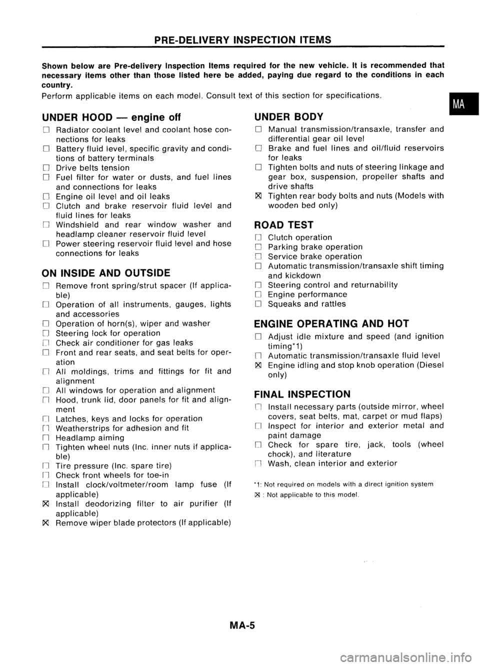
PRE-DELIVERYINSPECTIONITEMS
Shown belowarePre-delivery InspectionItemsrequired forthe new vehicle. Itis recommended that
necessary itemsotherthanthose listedherebeadded, payingdueregard tothe conditions ineach
country.
Perform applicable itemsoneach model. Consult textofthis section forspecifications .
UNDER HOOD-engine off
o
Radiator coolantlevelandcoolant hosecon-
nections forleaks
o
Battery fluidlevel, specific gravityandcondi-
tions ofbattery terminals
o
Drive beltstension
D
Fuel filter forwater ordusts, andfuel lines
and connections forleaks
[] Engine oillevel andoilleaks
D
Clutch andbrake reservoir fluidlevel and
fluid lines forleaks
o
Windshield andrear window washerand
headlamp cleanerreservoir fluidlevel
D
Power steering reservoir fluidlevel andhose
connections forleaks
ON INSIDE ANDOUTSIDE
D
Remove frontspring/strut spacer(Ifapplica-
ble)
D
Operation ofall instruments, gauges,lights
and accessories
o
Operation ofhorn(s), wiperandwasher
[] Steering lockforoperation
[] Check airconditioner forgas leaks
o
Front andrear seats, andseat belts foroper-
ation
n
All moldings, trimsandfittings forfitand
alignment
[J
Allwindows foroperation andalignment
n
Hood, trunklid,door panels forfitand align-
ment
[1
Latches, keysandlocks foroperation
rl
Weatherstrips foradhesion andfit
[l
Headlamp aiming
I~ Tighten wheelnuts(Inc. inner nutsifapplica-
ble)
IJ Tire pressure (Inc.spare tire)
Il
Check frontwheels fortoe-in
IJ Install clock/voltmeter/room lampfuse(If
applicable)
~ Install deodorizing filtertoair purifier (If
applicable)
~ Remove wiperbladeprotectors (Ifapplicable)
UNDER
BODY
o
Manual transmission/transaxle, transferand
differential gearoillevel
D
Brake andfuel lines andoil/fluid reservoirs
for leaks
D
Tighten boltsandnuts ofsteering linkageand
gear box,suspension, propellershaftsand
drive shafts
~ Tighten rearbody boltsandnuts (Models with
wooden bedonly)
ROAD TEST
D
Clutch operation
D
Parking brakeoperation
[J
Service brakeoperation
D
Automatic transmission/transaxle shifttiming
and kickdown
[] Steering controlandreturnability
o
Engine performance
D
Squeaks andrattles
ENGINE OPERATING ANDHOT
D
Adjust idlemixture andspeed (andignition
timing*1)
n
Automatic transmission/transaxle fluidlevel
~ Engine idlingandstop knob operation (Diesel
only)
FINAL INSPECTION
n
Install necessary parts(outside mirror,wheel
covers, seatbelts, mat,carpet ormud flaps)
[1
Inspect forinterior andexterior metaland
paint damage
[] Check forspare tire,jack, tools (wheel
chock), andliterature
n
Wash, cleaninterior andexterior
"1: Not required onmodels withadirect ignition system
~ :Not appiicable tothis model.
•
MA-5
Page 1651 of 1701
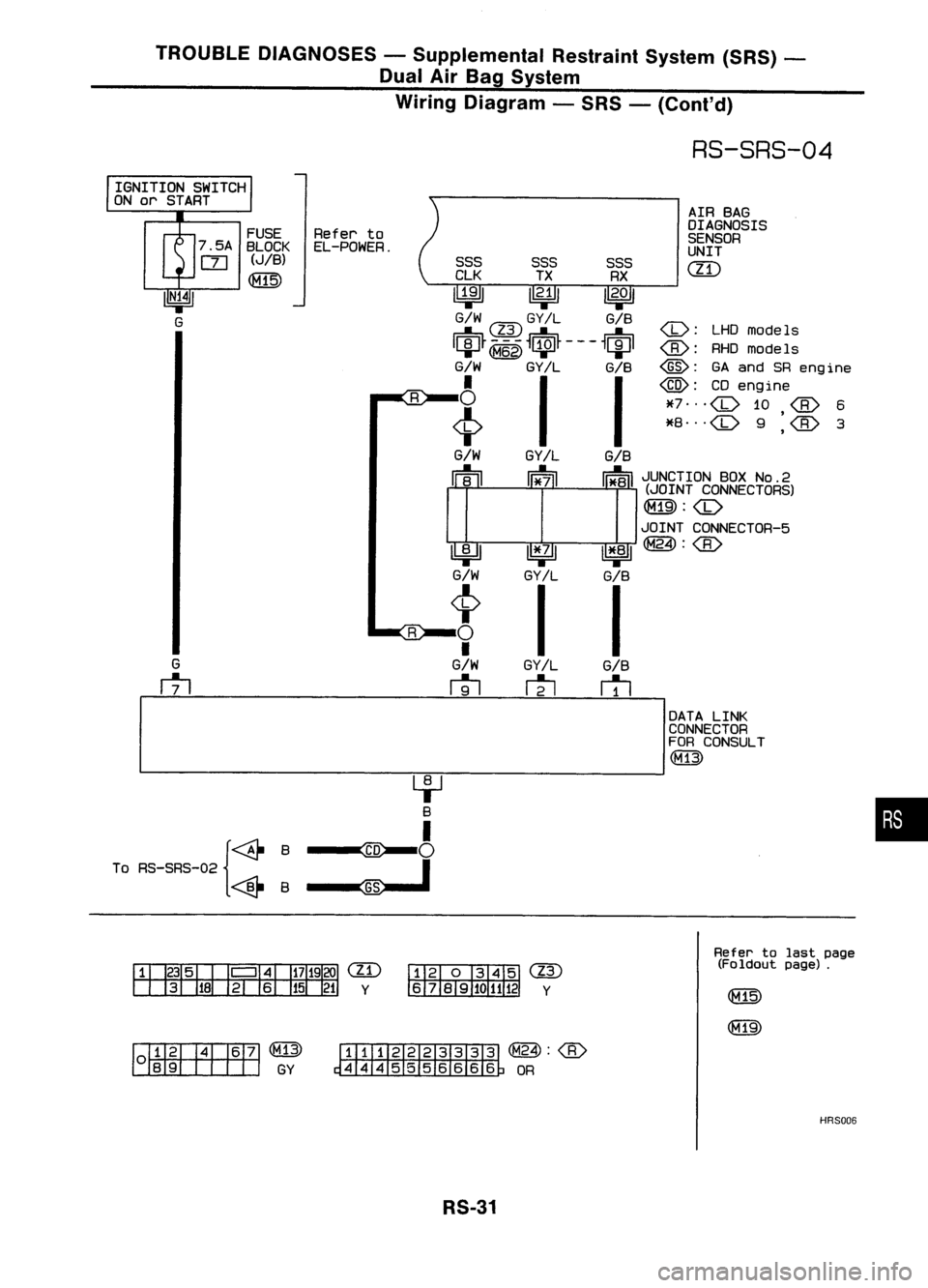
TROUBLEDIAGNOSES -Supplemental RestraintSystem(SRS)-
Dual AirBag System
Wiring Diagram -SRS -(Cont'd)
RS-SRS-04
AIR BAG
OIAGNOSIS
SENSOR
UNIT
em
:
LHOmodels
@:
GAand SReng ine
@:
CDengine
*7 ...
,
*8 ...
,
G/B
~
GY/L
~
~
G/W
t
o
•
G/W
~
SSS
SSSSSS
ClK TXRX
~ ~11
2
.°1
G/W
@
GY
IL
G/B
IciJ~
G/W
GY/L
G/B
i
II
G/W
GY/L
G/B
~ ~~JUNCTION BOXNO.2
II B.II 11*711 II*BII(JOINT CONNECTORS)
JOINT CONNECTOR-5
1*:1 II*.BI~:
GY/l
G/B
I I
FUSE
Referto
7 .5A BLOCK El-POWER.
rn
(JIB)
~
G
rtl
IGNITION
SWITCH
ON or START
4-J
B
I
To RS-SRS-02 {~B ~
i
<@-B~
•
em
Y
@
Y
Refer
tolast page
(Foldout page).
~Q@
~GY
~(M24):
~ OR
HRS006
RS-31