Page 205 of 1701

__________ BODYALIGNMENT _
_ PRECAUTIONS _
Description PrecautionsForHandling HighStrength Steel
• Alldimensions indicatedinfigures areactual ones.
• When usingatracking gauge,adjustbothpointers toequal length. Thencheck thepointers andgauge
itself tomake surethere isno free play.
• When ameasuring tapeisused, check tobe sure there isno elongation, twistingorbending.
• Measurements shouldbetaken atthe center ofthe mounting holes.
• Anasterisk
(*)
following thevalue atthe measuring pointindicates thatthemeasuring pointonthe other
side issymmetrically thesame value.
• The coordinates ofthe measurement pointsarethe distances measured fromthestandard lineof"X", "V"
and "Z".
EngineCompartment
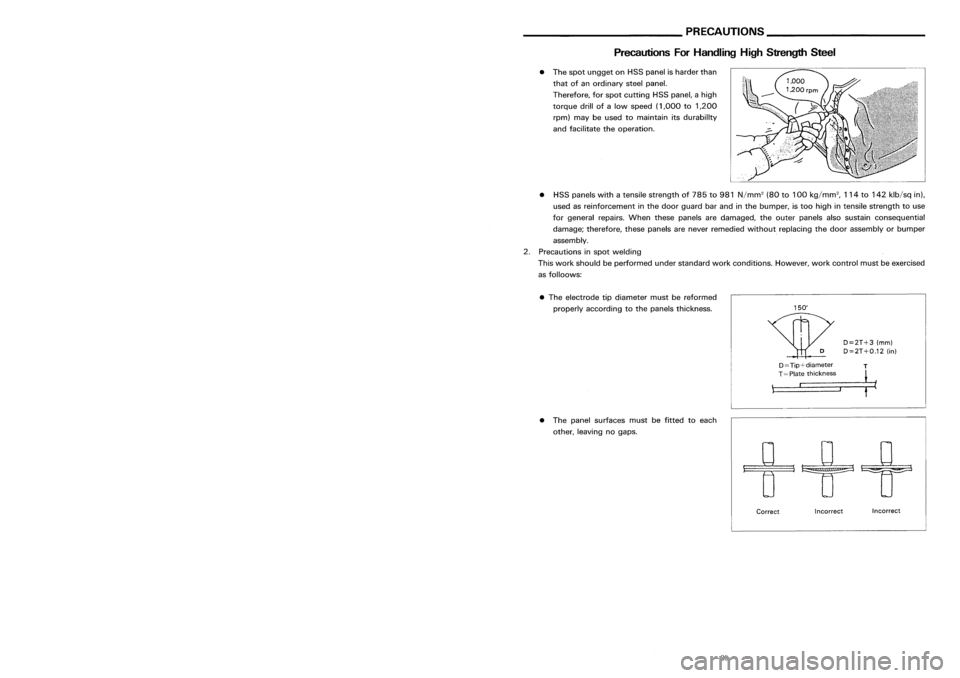
D=2T+3(mm)
D=2T+O.12 (in)
•
The electrode tipdiameter mustbereformed
properly according tothe panels thickness.
•
The spot ungget onHSS panel isharder than
that ofan ordinary steelpanel.
Therefore, forspot cutting HSSpanel, ahigh
torque drillofalow speed (1,000 to1,200
rpm) maybeused tomaintain itsdurability
and facilitate theoperation.
• HSS panels withatensile strength of785 to981 N/mm
2
(80to100 kg/mm
2,
114to142 klb/sq in),
used asreinforcement inthe door guard barand inthe bumper, istoo high intensile strength touse
for general repairs.Whenthesepanels aredamaged, theouter panels alsosustain consequential
damage; therefore, thesepanels arenever remedied withoutreplacing thedoor assembly orbumper
assembly.
2. Precautions inspot welding
This work should beperformed understandard workconditions. However,workcontrol mustbeexercised
as folloows:
SBF8?4GB
"Z":
Imaginary baseline
[200 mmbelow datum line
("OZ" atdesign plan)]
Front axlecenter
/
y (_)
(0)
Incorrect
Incorrect
Correct
D==Tip+diameter
T
,::=T====p=la::t_e=-=-_t_h=i_C=k=_n=_e_s=s= __,-- ~
• The panel surfaces mustbefitted toeach
other, leaving nogaps.
____
MEASURMENT _
SBT08?
-15- -30-
Page 208 of 1701
REPLACEMENTOPERATIONS _
------------
RadiatorCoreSupport (PartialReplacement) BODY
CONSTRUCTION _
-----------
BodyConstruction
\
Section
L-L:
Section P-P:
Section
D-D:
Section H-H:
Section K-K:
Section
C-C:
Section G-G:
Section 0-0:
Section
J-J:
Section
F-F:
Section
8-8:
. Section N-N:
Section
I-I:
Section
E-E:
Section
A-A:
Section M-M:
_1
FR
(
e
4orll3 *
indicates thatthere isan equivalent wel~ing.portion
with thesame dimensions onthe opposite Side.
o
*
e
3
or 112
FR
Service
Joint
Section
0-0:
Section
R-R:
2-spot welds 3-spotwelds
M.1.Gplug weld )M.I.Gseam weld/
(Point weld
For 3panels plugweld m.ethod
· r ·
A
=='*= •
B
===:=
.an
F
-33- -12-
Page 267 of 1701
BODYALIGNMENT
• Alldimensions indicatedinfigures areactual ones.
• When usingatracking gauge,adjustbothpointers toequal length. Thencheck thepointers and
gauge itselftomake surethere isno free play.
• When ameasuring tapeisused, check tobe sure there isno elongation, twistingorbending.
• Measurements shouldbetaken atthe center ofthe mounting holes.
• Anasterisk
(*)
following thevalue atthe measuring pointindicates thatthemeasuring pointonthe
other sideissymmetrically thesame value.
• The coordinates ofthe measurement pointsarethedistances measured fromthestandard lineof
"X", "Y"andHZ".
Frontaxlecenter
I
v
~
/
y
H
(0)
2
(+)
~r
L"oo"
b.~
Ii"'
"2": Imaginary baseline
[200 mmbelow datum line
("02" atdesign plan)]
MEASUREMENT
SBF874GB
Engine Compartment
SBT087
8T-47
•
Page 1187 of 1701
PREPARATION
Commercial ServiceTools
Engine
Tool name Description application
GA
SRCD
Spark plugwrench
0
Removing
andinstalling
Q
spark
plug
XX
16
mm
(0.63
In)
NT047
Valve seatcutter set
~
Finishing
valveseat
dimensions
XX
X
NT048
Piston ringexpander
~
Removing
andinstalling
piston ring
X
X
X
NT030
Valve guidedrift Removingandinstalling
'~
valve
guide
SR
Intake
&
Exhaust
XX
a
=
9.5
mm
(0.374 in)dia.
b
=
5.0
mm
(0.197 in)dia.
GA
Inlake
&
Exhaust
a
=
9.5
mm
(0.374 In)dla.
NT015
b
=
5.5
mm
(0.217 in)dla.
Valve guide reamer
Reaming
valve
guide
G)
or hole foroversize valve
~
guide
@
d,
\J
SR
Intake
&
Exhausl
XX
d,
=
6.0
mm
(0.236 in)dia.
@
d,
=
10.175
mm
(0.4006 in)
dia.
GA
Intake
&
Exhausl
d,
=
5.5
mm
(0.217 in)dia.
d,
=
9.685
mm
(0.3813 in)
NT016
dia.
Front oilseal drift
Installingfrontoilseal
XX
a
=
75
mm
(2.95 In)dla.
NT049
b
=
45
mm
(1.77 in)dia.
Rear oilseal drift
Installingrearoilseal
X
X
a
=
110
mm
(4.33 In)dla.
NT049
b
=
80
mm
(3.15 in)dia.
EM-8
Page 1218 of 1701

T(Margin thickness)
--1,-
ml
a
III' ~
o
~-
-L
d
SEM8928
I
.\
SEM188A
CYLINDER
HEAD
Inspection (Conl'd)
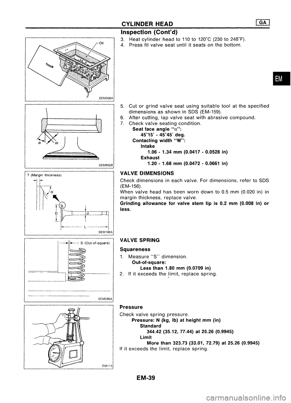
3. Heat cylinder headto110 to120°C (230to248°F).
4. Press fitvalve seatuntilitseats onthe bottom .
5. Cut orgrind valve seatusing suitable toolatthe specified
dimensions asshown inSOS (EM-159).
6. After cutting, lapvalve seatwithabrasive compound.
7. Check valveseating condition.
Seat faceangle "a":
45°15' -45°45' deg.
Contacting width"W":
Intake
1.06 -1.34 mm(0.0417 -0.0528 in)
Exhaust
1.20 -1.68 mm(0.0472 -0.0661 in)
VALVE DIMENSIONS
Check dimensions ineach valve. Fordimensions, refertoSOS
(EM-156).
When valveheadhasbeen worn down to0.5 mm (0.020 in)in
margin thickness, replacevalve.
Grinding allowance forvalve stemtipis0.2 mm (0.008 in)or
less.
•
SEM288A VALVE
SPRING
Squareness
1. Measure "S"dimension.
Out-of-square: Less than1.80mm(0.0709 in)
2. Ifitexceeds thelimit, replace spring.
EM113
Pressure
Check valvespring pressure.
Pressure: N(kg, Ib)atheight mm(in)
Standard 344.42 (35.12, 77.44)at25.26 (0.9945)
Limit More than323.73 (33.01, 72.79)at25.26 (0.9945)
If itexceeds thelimit, replace spring.
EM-39
Page 1271 of 1701

T(Margin thickness)
~I
r
nw
a
III' ~
D
L
-l
d
SEM892B
SEM188A CYLINDER
HEAD
Inspection (Cont'd)
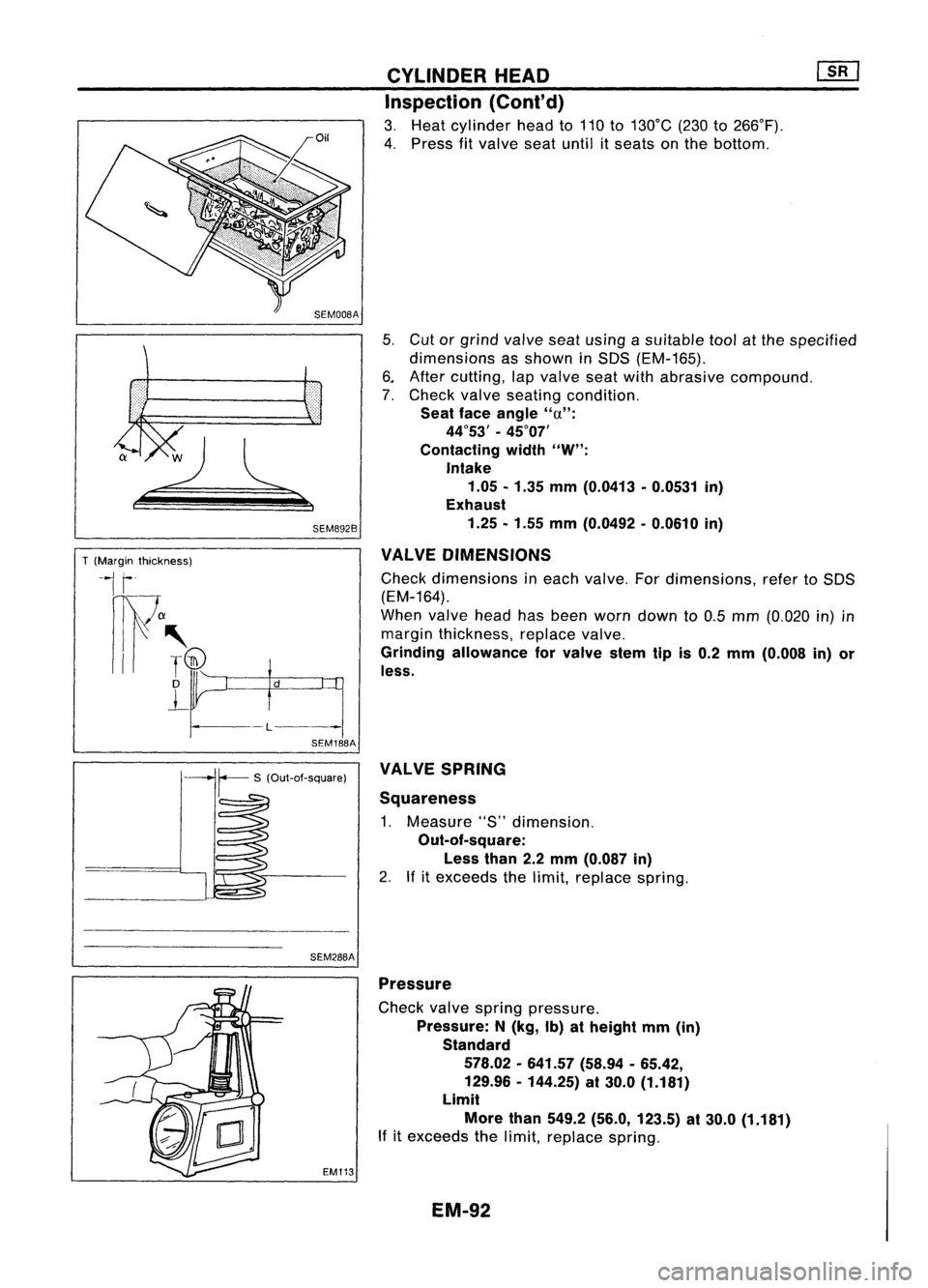
3. Heat cylinder headto110 to130°C (230to266°F).
4. Press fitvalve seatuntil itseats onthe bottom.
5. Cut orgrind valve seatusing asuitable toolatthe specified
dimensions asshown inSDS (EM-165).
6. After cutting, lapvalve seatwithabrasive compound.
7. Check valveseating condition.
Seat faceangle
"u":
44°53' -45°07'
Contacting width
"W":
Intake 1.05 -1.35 mm(0.0413 -0.0531 in)
Exhaust
1.25 -1.55 mm(0.0492 -0.0610 in)
VALVE DIMENSIONS
Check dimensions ineach valve. Fordimensions, refertoSDS
(EM-164).
When valveheadhasbeen worn down to0.5 mm (0.020 in)in
margin thickness, replacevalve.
Grinding allowance forvalve stemtipis0.2 mm (0.008 in)or
less.
SEM288A VALVE
SPRING
Squareness
1. Measure "S"dimension.
Out-of-square:
Less than2.2mm (0.087 in)
2. Ifitexceeds thelimit, replace spring.
EM113 Pressure
Check valvespring pressure.
Pressure: N(kg, Ib)atheight mm(in)
Standard
578.02 -641.57 (58.94-65.42,
129.96 -144.25) at30.0 (1.181)
Limit
More than549.2 (56.0, 123.5) at30.0 (1.181)
If itexceeds thelimit, replace spring.
EM-92
Page 1311 of 1701
![NISSAN ALMERA N15 1995 Service Manual
I
Recess
I
diameter
W: Refer toSOS.
I
SEM795A
SEMB76
SEM877
SEM635AA CYLINDER
HEAD
[£Q]
Inspection (Cont'd)
VALVE SEATREPLACEMENT
1. Bore outoldseat untilitcollapses.
Set machine depthst NISSAN ALMERA N15 1995 Service Manual
I
Recess
I
diameter
W: Refer toSOS.
I
SEM795A
SEMB76
SEM877
SEM635AA CYLINDER
HEAD
[£Q]
Inspection (Cont'd)
VALVE SEATREPLACEMENT
1. Bore outoldseat untilitcollapses.
Set machine depthst](/manual-img/5/57349/w960_57349-1310.png)
I
Recess
I
diameter
W: Refer toSOS.
I
SEM795A
SEMB76
SEM877
SEM635AA CYLINDER
HEAD
[£Q]
Inspection (Cont'd)
VALVE SEATREPLACEMENT
1. Bore outoldseat untilitcollapses.
Set machine depthstopsothat boring cannot contact bot-
tom face ofseat recess incylinder head.
2. Ream thecylinder headrecess.
Reaming boreforservice valveseat
[Oversize 0.5mm (0.020 in)]:
Intake 41.432 -41.454 mm(1.6312 -1.6320 in)
Exhaust 35.432-35.454 mm(1.3950 -1.3958 in)
Use thevalve gUide center forreaming toensure valveseatwill
have thecorrect fit.
3. Heat cylinder headtoatemperature of150 to160°C (302to
320°F) andpress fitseat untilitseats onthe bottom.
4. Install valveseats.
When replacing valveseat,valve should bereplaced aswell.
5. Cut orgrind valve seatusing asuitable toolatthe specified
dimensions asshown inSOS (EM-172).
The cutting shouldbedone withboth hands toobtain auniform
and concentric finish.
6. Apply asmall amount offine grinding compound tothe
valve's contacting faceandputthe valve intoitsguide.
Lap valve against itsseat untilproper valveseating is
obtained.
7. Check valveseating condition.
EM-132
Page 1312 of 1701
T(Margin thickness)
II
~a
.
,
I
T(Th)
D
L
CYLINDER
HEAD @Q]
Inspection (Cont'd)
VALVE DIMENSIONS
1. Check dimensions ofeach valve. Fordimensions, referto
SDS (EM-171).
2. Correct orreplace anyvalve thatisfaulty .
d •
L-~
SEM188A
3.Valve faceorvalve stemendsurface shouldberefaced by
using avalve grinder.
When valveheadhasbeen worn down to0.5 mm (0.020 in)in
margin thickness, replacethevalve.
Grinding allowance torvalve stemtipis0.5 mm (0.020 in)or
less.
VALVE SPRING SQUARENESS
Check valvespring forsquareness usingasteel square andflat
surface plate.
If
spring isout ofsquare "S"more thanspecified limit,replace
with newone.
Out-at-square: OuterLess than2.1mm (0.083 in)
Inner less than1.9mm (0.075 in)
•
SEM333
VALVE SPRING PRESSURE LOAD
Measure thefree length andthetension ofeach spring. Ifthe
measured valueexceeds thespecified limit,replace spring.
Refer toSDS (EM-172).
EM113 HYDRAULIC VALVELIFTER
1. Check contact andsliding surfaces forwear orscratches .
SEM7238 EM-133