Page 1450 of 1701
TROUBLEDIAGNOSES
Wiring Diagram -
A/C -
(Cont'd)
CD20 engine models
HA-A/C-11
IGNITION SWITCH
ON or START
:
LHDmode 1s
@:
RHDmodels
tt
I
I
BR G/WLG/R
COOLING1:}:1
:!J'
I~II
FAN
nn
RELAY-3
UU
((@
I'=idI
IliJI~
LG G/OR B
1--1
FUSE
r1!Jj;1]
RefertoEL-POWER.
10A BLOCK 30A30A
1251
(J/B)
(Et06)
0
[B]
GY G/W
1---1
_ ....-,-I-F.
,-1=
BR GYG/W BRGYLG/B
COOLING1:Jt1 1::11
I~II
COOLING
1
:!: ::JI
::II
FAN
nn
FAN
nn
RELAY-1
UU
RELAY-2
UU
llli>
I'=idI
IliJI ~ ~
I'=idI
Iki=ll~
LG/R G/BG/R LGG/Y B
~ 1-1_
I..J
1_
r~-CJI::~.
971~
G/BG/YCOOLING
<;::J:=;> ~
dbdbFAN
LG Ifii\i\LG/R LGIfii\i\LG/R II111 II2 II MOTOR-1
,..,Ib ~ ~
r::::!=~ r::::!=
LaHi
IE"4S
~-M-a-~ "1rlt-M-a-iI3.r1l (+)(+)~
LG
CHID
LG/R LG
CHID
LG/R
M
~£:r
HiHi
O~I.
R
ijl ijl
I
0
LG/BB LG/RB
tt
LG
t
L:/R
t
LI
L...I
r'
IFffill
m
ECM _,
1.____...,
R/FAN2 R/FAN1 (ENGINE
CONTROL BB
MODULE)
-!--!-
@
~ llli>,@,((@
~BR BRBR
~@,~
~ GYGY
Refer
tolast page
(Foldout page).
CHID
(EiOt)
,
~
HHA011
HA-48
Page 1493 of 1701

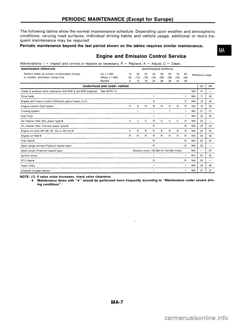
PERIODICMAINTENANCE (ExceptforEurope)
The following tablesshowthenormal maintenance schedule.Depending uponweather andatmospheric
conditions, varyingroadsurfaces, individual drivinghabitsandvehicle usage,additional ormore fre-
quent maintenance mayberequired.
Periodic maintenance beyondthelast period shown onthe tables requires similarmaintenance .
Engine andEmission ControlService
•
Abbreviations: I
=
Inspect andcorrect orreplace asnecessary. R
MAINTENANCE OPERATION
Perform eitheratnumber ofkilometers (miles)
or months, whichever comestirst. km
x1,000
(Miles x1,000)
Months
Replace.
A
=
Adjust, C
=
Clean.
MAINTENANCE INTERVAL
10 20 3040
506070
80
Reference page
(6) (12) (18)
(24)(30)(36)(42)(48)
6 12 18
24
3036
42 48
Underhood andunder vehicle GA
SR
Intake
&
exhaust valveclearance (GA15DE
&
GA16DE engines) SeeNOTE (1)
EM41
-
Drive belts
II
MA 17
24
Engine anti-Ireeze coolant(Ethylene glycolbase)(LLC) RRMA 1929
Engine coolant (Softwater) RRR
R
R R
R
RMA
1929
Cooling system
I
I
I
I
MA 2131
Fuel lines
I
I
MA
22
32
Air cleaner filter(Drypaper type)*
CC
C RC CC RMA 23
-
Air cleaner filter(Viscous papertype)* R
RMA
2333
Engine oil(Use APISE,SF.SGorSH oil)*
R
RRRR R
RR
MA 24
33
Engine oilfilter* R
R R
R
R RRRMA
2433
Fuel filter* R
RMA
22
32
Spark plugs(except Platinum-tipped type) R
RMA
25
-
Spark plugs(platinum-tipped type) Replaceevery100,000 km(60.000 miles). MA
-
34
Ignition wires
I
I
MA
2635
PCV filter* R
RMA
26
-
Vapor lines
I
I
MA
26
36
(Heated) OxygenSensor
I
I
MA 2737
NOTE: (1)
If
valve noiseincreases, checkvalveclearance.
*
Maintenance itemswith
"*"
should beperformed morefrequently accordingto"Maintenance undersevere driv-
ing conditions".
MA-7
Page 1496 of 1701

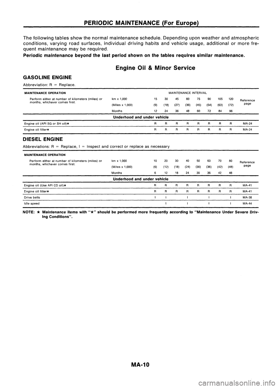
PERIODICMAINTENANCE (ForEurope)
The following tablesshowthenormal maintenance schedule.Depending uponweather andatmospheric
conditions, varyingroadsurfaces, individual drivinghabitsandvehicle usage,additional ormore fre-
quent maintenance mayberequired.
Periodic maintenance beyondthelast period shown onthe tables requires similarmaintenance.
Engine Oil
&
Minor Service
GASOLINE ENGINE
Abbreviation: R
=
Replace.
MAINTENANCE OPERATION
Perform eitheratnumber ofkilometers (miles)or
months, whichever comesfirst. km
x1,000
(Miles x1,000)
Months MAINTENANCE
INTERVAL
15 30 45
60 75
90105
120
Reference
(9) (18) (27) (36)(45)(54) (63)(72) page
12 24 3648 6072 84
96
Underhood andunder vehicle
Engine
011
(API SGorSH
011)*
Engine oilfiller*
DIESEL ENGINE
R
R R
R R
R
R
R
R
R
R
R
R
R
R
R
MA-24
MA-24
Abbreviations: R
=
Replace, IInspect
andcorrect orreplace asnecessary
MAINTENANCE OPERATION
Perform eitheratnumber ofkilometers (miles)or kmx1,000 10
20 30
40
5060 70
80
Reference
months, whichever comesfirst.
(30)(36) page
(Miles x1,000) (6)(12) (18) (24)
(42)
(48)
Months 612
1824
3036 42
48
Underhood andunder vehicle
Engine oil(Use APiCDoil)* R
RRR
RR R
R MA-41
Engine oilfilter* R
RRR RR RR MA-41
Drive belts MA-38
Idle speed MA-44
NOTE:
*
Maintenance itemswith
"*"
should beperformed morefrequently accordingto"Maintenance UnderSevere Driv-
ing Conditions".
MA-10
Page 1649 of 1701
TROUBLEDIAGNOSES -Supplemental RestraintSystem(SRS)-
Dual AirBag System
Wiring Diagram -SRS -
DUAL AIRBAG SYSTEM
RS-SRS-02
IGNITION SWITCH
ON orSTART
::} ToAS-SAS-D.
•
Refer
toEL-POWER.
LHOmode Is
RHOmodels
@:
GAand SRengine
@:
CDengine
@:
Withtachometer
@:
Without tachometer
~f1 ...
@
30
@
40
,
*2
@
9
@
31
*3
@
16
'@
30
,
AIR
BAG
DIAGNOSIS
SENSOR
UNIT
ill)
FUSE
BLOCK
(JIB)
(M15)
10A
1221
IGN
GNO
~ B
~(ll)
C:J~
B
rn~
I
~g~~~CTOR-3
~:
JOINT
CONNECTOR-4
~~:
I
,..O~O-O-ID-
I
<:
R
:>
I~
B B B BB
1
L..t t.J
~ (M60)~
~
(ll)"
*~
BRIW ~ BRIW-.
COMBINATION BRIW
METER ~
(AIR BAG 111511
WARNING WIL
LAMP)
(M30)
~
10A
W
BIR
.....
~
11*.21
BIR
~----------------------------------~
Refertolast page
(Foldout page).
L ~
em
y
(IT)
y
~(M59):
~P
ITIII:illJIIIII
~:
~ BR
HRS004
RS-29
Page 1650 of 1701
TROUBLEDIAGNOSES -Supplemental RestraintSystem(SRS)-
Dual AirBag System
Wiring Diagram -SRS -
{Co nt'd)
RS-SRS-03
AIRBAG
DIAGNOSIS
SENSOR
UNIT
em
AIR BAG
MODULE
PASSENGER
SIDE (SQUIB)
t
SQ-
(PASS)
~
OR
SQ+
(PASS)
~
G
SPIRAL
CABLE
AIR BAG
MODULE
DRIVER'S
SIDE (SQUIB)
t
SQ-
(DR)
~
L
SQ+
(DR)
l!:jJJ
W
DOOR
SWITCH
DRIVER'S
SIDE
@)
OPEN
"=iJ
B
I
f.
B B
~ ~
(B11)
@
DOOR
SW
~
R
~@
ICiJI~
R
I
BOXNO.2
(..JOINT
R CONNECTORS)
I~I ~~: ; ~
R R
I"'m:\
~~
I~IC@
R
<;>
R
0
•
R
m
em
y
@
~cm
y ~ y
Refer
tolast page
(Foldout page).
~~@
5 6lil~1112 W
rfrnl(]ID
l]f
B
~
*6
A,.@
t!!Iy ~y
@
W
HRS005
RS-30
Page 1651 of 1701
TROUBLEDIAGNOSES -Supplemental RestraintSystem(SRS)-
Dual AirBag System
Wiring Diagram -SRS -(Cont'd)
RS-SRS-04
AIR BAG
OIAGNOSIS
SENSOR
UNIT
em
:
LHOmodels
: RHOmodels
@:
GAand SReng ine
@:
CDengine
*7 ...
10 6
,
*8 ...
9 3
,
G/B
~
GY/L
~
~
G/W
t
o
•
G/W
~
SSS
SSSSSS
ClK TXRX
~ ~11
2
.°1
G/W
@
GY
IL
G/B
IciJ~
1$~ -- -1$1
G/W
GY/L
G/B
i
II
G/W
GY/L
G/B
~ ~~JUNCTION BOXNO.2
II B.II 11*711 II*BII(JOINT CONNECTORS)
JOINT CONNECTOR-5
1*:1 II*.BI~:
GY/l
G/B
I I
FUSE
Referto
7 .5A BLOCK El-POWER.
rn
(JIB)
~
G
rtl
IGNITION
SWITCH
ON or START
4-J
B
I
To RS-SRS-02 {~B ~
i
<@-B~
•
em
Y
@
Y
Refer
tolast page
(Foldout page).
~Q@
~GY
~(M24):
~ OR
HRS006
RS-31
Page 1662 of 1701
TROUBLEDIAGNOSES -Supplemental RestraintSystem(SRS)-
Single AirBag System
Wiring Diagram -SRS -
SINGLE AIRBAG SYSTEM
RS-SRS-01
IGNITION SWITCH
ON orSTART
AIRBAG
DIAGNOSIS
SENSOR
UNIT
Refer
toEL-POWER.
SPIRAL
CABLE
@:
Withtachometer
@:
Without tachometer
i(f ...
@
30
@
40
*2"'@9'@31
,
*3 ... @16 @30
,
FUSE
BLOCK
(J/B)
~
3A
1211
10A
rn
CHID
m
~BR/W~F.BR/W~
I
GID@!)
I
O-JD- BR/W.3ID)- BR/W-:E-O
Y
B!wt I
Ii*llJ
":3
I
t
COMBINA nON BR/W~ R/W B
METER
m-~~ffl---m
(AIR BAG
WARNING
LAMP)
@)
~
U*.21
B/R
B/R
-!-
~ AIR
BAG
MODULE (SQUIB)
rT
B B
~ ~
~ @D
I
I
1
I
I
I
L
~
r-----------------,
I I
1 ~I
1~*4 3*5
1
: [g]lJTIJ
W4Y :
I 1
L
~
~
lIL..m
BR
Refer
tolast page
(Foldout page).
HRS003
RS-42