Page 1531 of 1701
CHASSISANDBODY MAINTENANCE
Checking ExhaustSystem
Check exhaust pipes,muffler andmounting forimproper attach-
ment andforleaks, cracks, damage, looseconnections, chafing
and deterioration. •
SMA211A Checking ClutchFluidLevel andLeaks
If fluid level isextremely low,check clutch system forleaks.
SMA449C Checking ClutchSystem
HYDRAULIC TYPE
Check fluidlines andoperating cylinderforimproper
attachment, cracks,damage, looseconnections, chafingand
deterioration.
jJ
I
SMA"",
MECHANICAL TYPE
Check cableandlinks forimproper attachment, chafing,wear
and deterioration.
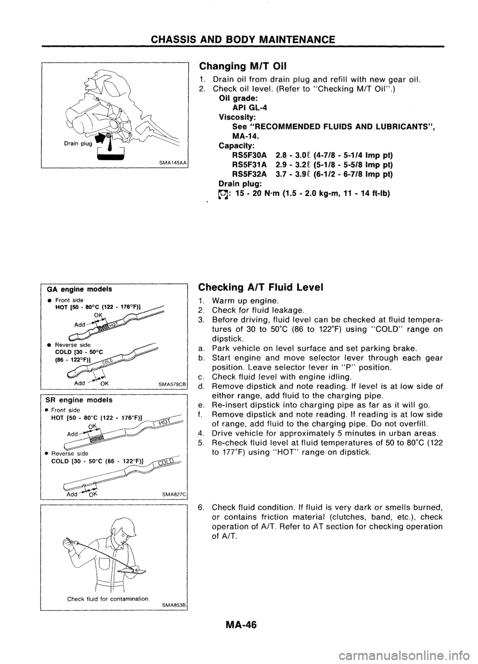
SMA141A Checking MITOil
• Check thatoilisnot leaking fromtransaxle oraround it.
• Remove speedometer pinionandcheck thattheoillevel L
at vehicle rearside iswithin specification.
Specified
Specifiedoillevel (Dimension L):
oil level
RS5F30A58-66 mm (2.28 -2.60 in)
RS5F31A GA engine 57-66 mm (2.24 -2.60 in)
CD engine 54-61 mm (2.13 -2.40 in)
RS5F32A 39-44 mm (1.54 -1.73 in)
SMT512C
MA-45
Page 1532 of 1701

CHASSISANDBODY MAINTENANCE
Changing
MIT
Oil
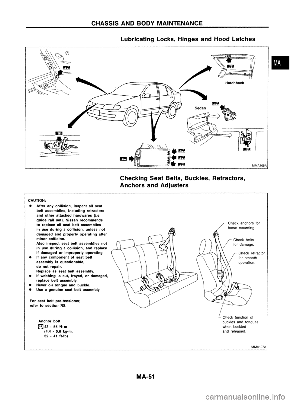
1. Drain oilfrom drain plugandrefill withnewgear oil.
2. Check oillevel. (Refer to"Checking
M/T
Oil".)
Oil grade:
API GL-4
Viscosity: See "RECOMMENDED FLUIDSANDLUBRICANTS",
MA-14.
Capacity: RS5F30A 2.8-3.0f
(4-7/8 -5-114
Imppi)
RS5F31A 2.9-3.2£
(5-1/8 -5-518
Imppt)
RS5F32A 3.7-3.9£ (6-112 -
6-7/8
Imppt)
Drain plug:
(OJ:
15-20 N'm (1.5-2.0 kg-m, 11-14 ft-Ib)
6. Check fluidcondition. Iffluid isvery dark orsmells burned,
or contains frictionmaterial (clutches, band,etc.),check
operation ofAlT. Refer toAT section forchecking operation
of AlT.
Checking
AIT
Fluid Level
1. Warm upengine .
2. Check forfluid leakage.
3. Before driving, fluidlevel canbechecked atfluid tempera-
tures of30 to50°C (86to122°F) using"COLD" rangeon
dipstick.
a. Park vehicle onlevel surface andsetparking brake.
b. Start engine andmove selector leverthrough eachgear
position. Leaveselector leverin"P" position.
c. Check fluidlevel withengine idling.
d. Remove dipstickandnote reading. Iflevel isat low side of
either range, addfluid tothe charging pipe.
e. Re-insert dipstickintocharging pipeasfar asitwill go.
f.
Remove dipstickandnote reading.
If
reading isat low side
of range, addfluid tothe charging pipe.Donot overfill.
4. Drive vehicle forapproximately 5minutes inurban areas.
5. Re-check fluidlevel atfluid temperatures of50 to80°C (122
to 177°F) using"HOT" rangeondipstick.
SMA827C
SMA579CB
GA
engine models
• Front side
HOT [50•80°C (122•176°F))
OK
SR engine models
• Front side
HOT [50•80"C (122-176"F)]
o'f..
Check fluidforcontamination.
SMA853B
MA-46
Page 1537 of 1701

CHASSISANDBODY MAINTENANCE
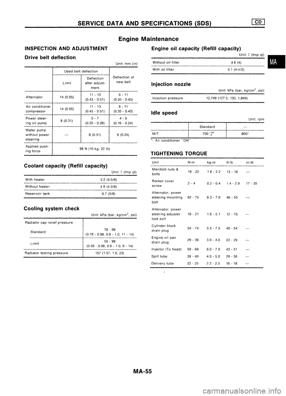
lubricating locks,Hinges andHood latches
•
MMA106A
Hatchback
/
"
m
S.d" ~
__ m__
~
CheckingSeatBelts, Buckles, Retractors,
Anchors andAdjusters
CAUTION: • After anycollision, inspectallseat
belt assemblies, includingretractors
and other attached hardwares (i.e.
guide railset). Nissan recommends
to replace allseat beltassemblies
in use during acollision, unlessnot
damaged andproperly operating after
minor collision.
Also inspect seatbeltassemblies not
in use during acollision, andreplace
if damaged orimproperly operating.
• Ifany component ofseat belt
assembly isquestionable,
do not repair.
Replace asseat beltassembly.
• If
webbing iscut, frayed, ordamaged,
replace beltassembly.
• Never oiltongue andbuckle.
• Use agenuine seatbeltassembly.
For seat beltpre.tensioner,
refer tosection RS.
Anchor bolt
tcJ
43•55 N.m
(4.4 •5.6 kg-m,
32 •41 ft.lb)
Check
anchors for
loose mounting.
Check function of
buckles andtongues
when buckled
and released.
MMA107A
MA-51
Page 1541 of 1701

SERVICEDATAANDSPECIFICATIONS (50S)
Used beltdeflection
Deflection Deflection
of
Limit afteradjust- new
belt
ment
Alternator 14(055) 11
-13 9-11
(0.43 -0.51)
(0.35-0.43)
Air conditioner
14(0.55) 11
-13
9-11
compressor (0.43
-0.51)
(0.35-0.43)
Power steer-
8(0.31) 5
-7
4-6
ing oilpump (0.20-0.28)
(0.16-0.24)
Water pump
without power
-
8
(0.31) 6(0.24)
steering
Applied push-
98N(10 kg, 22Ib)
ing force
Coolant capacity (Refillcapacity)
INSPECTION
ANDADJUSTMENT
Drive beltdeflection
Unit:kPa(bar, kg/cm', psi)
12,749 (127.5, 130,1,849)
Without
oilfilter
With oilfilter
Injection pressure
Injection
nozzle
Idle speed
Unit:rpm
Standard
M/T
700
'go
800'
': Air conditioner "ON"
TIGHTENING TORQUE
Unit N'mkg-m
ft-Ib in-Ib
Manifold nuts
&
18-22
1.8-2.2
bolts 13
-16
Rocker cover
2-4
0.2-0.4 1.4-2.9 17-35
screw
Alternator, power
steering mounting 62-75
6.3-76 46
-55
bolt
Alternator, power
steering adjuster 16
-21
1.6-2.1
12-15
lock bolt
Cylinder block
54-74
5.5-7.5 40
-54
drain plug
Engine oilpan
29-39 3.0-4.0 22-29
drain plug
Injector (Tohead)
59-69 6.0-7.0 43-51
Spill tube 39-49
4.0-5.0 29-36
Delivery tube 22-25 2.2-2.5
16-18
Engine
Maintenance
Engine oilcapacity (Refillcapacity)
Unit:[(Imp qt)•
46 (4)
51 (4--1/2)
Unit:
mm(in)
Unit:
f
(Imp qt)
5.2 (4-5/8)
49 (4-3/8)
0.7 (5/8)
Unit: kPa(bar, kg/cm', psi)
78 -98
(0.78 -0.98, 08-1.0, 11-14)
59 -98
(0.59 -0.98, 06-10, 9-14)
157 (1.57, 1.6,23)
Standard
Limit
With
heater
Without heater
Reservoir tank
Radiator caprelief pressure
Radiator testingpressure
Cooling
systemcheck
MA-55
Page 1543 of 1701

MANUALTRANSAXLE
SECTION
MT
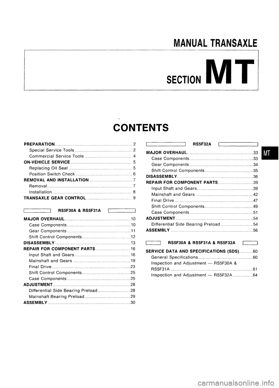
CONTENTS
PREPARATION 2
Special Service Tools 2
Commercial ServiceTools 4
ON-VEHICLE SERVICE
5
Replacing OilSeal 5
Position SwitchCheck 6
REMOVAL ANDINSTAllATION 7
Removal ,7
Installation '8
TRANSAXlE GEARCONTROL 9
RS5F30A
&
RS5F31 A
MAJOR OVERHAUL 10
Case Components 10
Gear Components ,11
Shift Control Components , 12
DiSASSEMBly ,13
REPAIR FORCOMPONENT PARTS 16
Input Shaft andGears 16
Mainshaft andGears 19
Final Drive ,,23
Shift Control Components 25
Case Components ,25
ADJUSTMENT ,,.. , 28
Differential SideBearing Preload 28
Mainshaft BearingPreload ,29
ASSEMBly ,30 RS5F32A
MAJOR OVERHAUl ,,,
33
Case Components , 33
Gear Components 34
Shift Control Components 35
DiSASSEMBly ",.,., , ,36
REPAIR FORCOMPONENT PARTS 39
Input Shaft andGears 39
Mainshaft andGears 42
Final Drive .47
Shift Control Components 49
Case Components ' 51
ADJUSTMENT ,, ", 54
Differential SideBearing Preload ,54
ASSEMBLY ',
56
'----_-JI RS5F30A
&
RS5F31A
&
RS5F32A
SERVICE DATAANDSPECIFICATIONS (SDS)60
General Specifications 60
Inspection andAdjustment -RS5F30A &
RS5F31 A ' 61
Inspection andAdjustment -RS5F32A 64
•
Page 1548 of 1701
SwitchGearposition Continuity
Reverse Yes
Back-up lampswitch
No
Except reverse
Neutral Yes
Neutral position switch
Exceptneutral No
3.
Remove strikingrodoilseal.
Position SwitchCheck
• Check continuity.
4.
Install striking rodoilseal.
• Apply multi-purpose greasetoseal lipofoil seal before
installing.
ON-VEHICLE
SERVICE
Replacing OilSeal (Cont'd)
STRIKING RODOILSEAL
1. Remove transaxle controlrodfrom yoke.
2. Remove yokeretaining pin.
• Becareful nottodamage boot.
DISCONNECT
eJ
Neutral position
switch harness
connector
~ SMT715BB
MT-6
Page 1557 of 1701
DISASSEMBLY RS5F30A
&
RS5F31 A
SMT648AA
KV32101000
SMT599AA
SMT583
/ Reverse checkplug
~ "Reverse checkspring
S/
V
Check ball(Large)
"--_Check ball(Small)
SMT584
SMT585
5.
Remove oilpocket, shiftcheck ball,shift check spring and
check ballplug.
6. Drive retaining pinout ofstriking lever,thenremove strik-
ing rod, striking leverandstriking interlock.
• Select aposition whereretaining pindoes notinterfere with
. clutch housing whenremoving retainingpin.
• Becareful nottodamage oilseal lip,when removing strik-
ing rod. Ifnecessary, tapeedges ofstriking rod.
7. Remove reversecheckplug,thendetach reverse check
spring andcheck balls,
8. Remove checksleeve assembly.
MT-15
•
Page 1567 of 1701
1/
REPAIR
FORCOMPONENT PARTS
I
RS5F30A
&
RS5F31A
I
Final Drive (Cont'd)
5. Install retaining pin.
• Make surethatretaining pinisflush withcase.
Retaining
pin
SMT147AA
6.Install finalgear.
• Apply locking sealant tofinal gear fixing boltsbefore install-
ing them.
7-. Install speedometer drivegearandstopper .
SMT609A
•
;?
Control
b~'Ck:t ,
.. ~-t'
If
0
Shift forkandshifter cap
",0
~ SMT086C
8.
Press ondifferential sidebearings.
Shift Control Components
INSPECTION
• Check contact surface andsliding surface forwear,
scratches, projections orother damage.
Case Components
Input shaftoilseal
1. Drive outinput shaftoilseal.
MT-25