Page 1618 of 1701
REARSUSPENSION
Coil Spring andShock Absorber (Conl'd)
DISASSEMBL Y
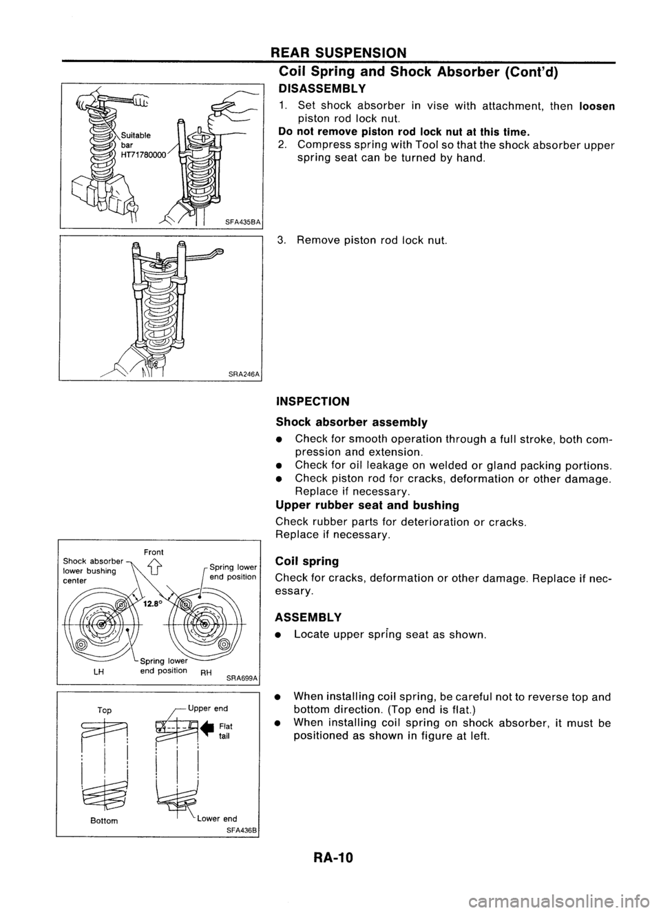
1. Set shock absorber invise withattachment, then
loosen
piston rodlock nut.
Do not remove pistonrodlock nutatthis time.
2. Compress springwithTool sothat theshock absorber upper
spring seatcanbeturned byhand.
3. Remove pistonrodlock nut.
INSPECTION
Shock absorber assembly
• Check forsmooth operation throughafull stroke, bothcom-
pression andextension.
• Check foroilleakage onwelded orgland packing portions.
• Check pistonrodforcracks, deformation orother damage.
Replace ifnecessary.
Upper rubber seatandbushing
Check rubber partsfordeterioration orcracks.
Replace ifnecessary.
ASSEMBLY
• Locate upperspring seatasshown.
Coil
spring
Check forcracks, deformation orother damage. Replaceifnec-
essary.
LH
RH
SRA699A
•
Top ~P"'"d
Ai
--
- • Flat
•
tail
i 'I
~ ~l_""d
Bottom
SFA4368
When
installing coilspring, becareful nottoreverse topand
bottom direction. (Topendisflat.)
When installing coilspring onshock absorber, itmust be
positioned asshown infigure atleft.
RA-10
Page 1636 of 1701
SUPPLEMENTALRESTRAINTSYSTEM(SRS)
Removal -Front Passenger AirBag Module
(Dual AirBag System)
CAUTION:
• Before servicing SRS,turntheignition switchoff,discon-
nect both battery cablesandwait foratleast 10minutes.
• Always workfromtheside ofor under airbag module.
1. Open theglove boxlid.
2. Disconnect inflatorconnector frombody harness airbag
connector.
3. Remove gloveboxassembly. Referto"INSTRUMENT
PANEL" inBT section fordetails.
Air bag
module
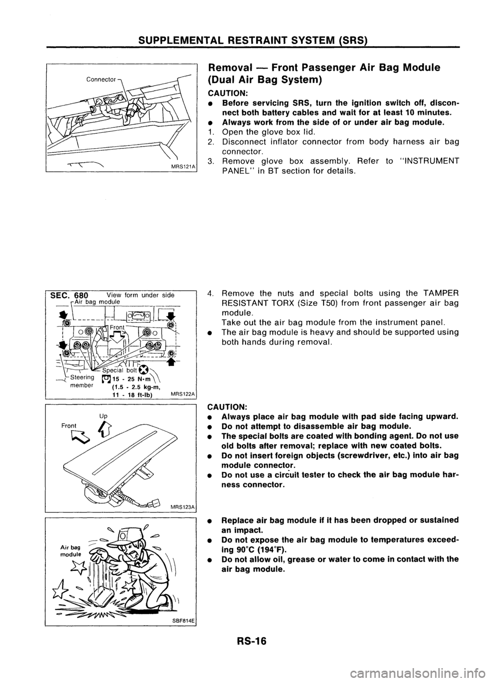
4.
Remove thenuts andspecial boltsusing theTAMPER
RESISTANT TORX(SizeT50jfrom front passenger airbag
module.
Take outtheairbag module fromtheinstrument panel.
• The airbag module isheavy andshould besupported using
both hands during removal.
MRS122A
CAUTION:
• Always placeairbag module withpadside facing upward.
• Donot attempt todisassemble airbag module.
• The special boltsarecoated withbonding agent.Donot use
old bolts afterremoval; replacewithnewcoated bolts.
• Donot insert foreign objects (screwdriver, etc.)intoairbag
module connector.
• Donot use acircuit testertocheck theairbag module har-
ness connector.
• Replace airbag module ifithas been dropped orsustained
an impact.
• Donot expose theairbag module totemperatures exceed-
ing 90°C (194°F).
• Donot allow oil,grease orwater tocome incontact withthe
air bag module.
SBF814E RS-16
Page 1667 of 1701
STEERINGSYSTEM
SECTIONST
CONTENTS
PRECAUTIONS ANDPREPARATION 2
Precautions 2
Special Service Tools 3
Commercial ServiceTools 4
ON-VEHICLE SERVICE
5
Checking SteeringWheelPlay 5
Checking NeutralPosition onSteering Wheel 5
Front Wheel Turning Angle 5
Checking GearHousing Movement 5
Checking andAdjusting DriveBelts(For
power steering) 6
Checking FluidLevel 6
Checking FluidLeakage 6
Bleeding Hydraulic System 7
Checking SteeringWheelTurning Force(For
power steering) 7
Checking Hydraulic System 8
STEERING WHEElANDSTEERING COLUMN 9
Removal andInstallation 9
Disassembly andAssembly 12
Inspection 13
MANUAL STEERING GEARANDLINKAGE
(Model R24N) 14
Removal
andInstallation 14
Disassembly 15
Inspection 15
Assembly andAdjustment... 16
POWER STEERING GEARANDLINKAGE (Model
PR24AC) 19
Removal andInstallation 19
Disassembly 22
Inspection 22
Assembly ,.. 23
Adjustment 27
POWER STEERING OILPUMP 29
Pre-disassembly Inspection 30
Disassembly 30
Inspection 31
Assembly 31
POWER STEERING OILCOOLER
33
Oil Cooler (Heavy dutykitfor CD20 engine
model) 33
Removal andInstallation 33
SERVICE DATAANDSPECIFICATIONS
(505)34
General Specifications 34
Inspection andAdjustment 34
•
Page 1672 of 1701
ON-VEHICLESERVICE
Checking andAdjusting DriveBelts(Forpower
steering)
Refer to"Checking DriveBelts" for"ENGINE MAINTENANCE"
in MA section.
SST476C
S
r
SST681B Checking
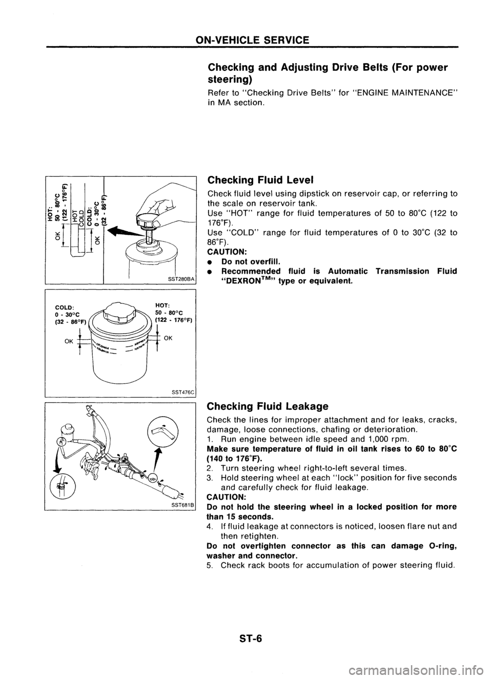
Fluidlevel
Check fluidlevel using dipstick onreservoir cap,orreferring to
the scale onreservoir tank.
Use "HOT" rangeforfluid temperatures of50 to80°C (122to
176°F).
Use "COLD" rangeforfluid temperatures of0to 30°C (32to
86°F).
CAUTION:
• Donot overfill.
• Recommended fluidisAutomatic Transmission Fluid
''DEXRON™,, typeorequivalent.
Checking Fluidleakage
Check thelines forimproper attachment andforleaks, cracks,
damage, looseconnections, chafingordeterioration.
1. Run engine between idlespeed and1,000 rpm.
Make suretemperature offluid inoil tank rises to60 to80°C
(140 to176°F).
2. Turn steering wheelright-to-Ieft severaltimes.
3. Hold steering wheelateach "lock" position forfive seconds
and carefully checkforfluid leakage.
CAUTION:
Do not hold thesteering wheelinalocked position formore
than 15seconds.
4. Iffluid leakage atconnectors isnoticed, loosenflarenutand
then retighten.
Do not overtighten connectorasthis candamage O-ring,
washer andconnector.
5. Check rackboots foraccumulation ofpower steering fluid.
ST-6
Page 1673 of 1701
SST491B
SST090B ON-VEHICLE
SERVICE
Bleeding Hydraulic System
1. Raise frontendofvehicle untilwheels areclear ofthe
ground.
2. Add fluid intooiltank tospecified level.Thenquickly turn
steering wheelfullytoright andleftand lightly touchsteer-
ing stoppers.
Repeat steering wheeloperation untilfluid level nolonger
decreases.
3. Start engine.
Repeat step2.above.
• Incomplete airbleeding willcause thefollowing tooccur.
When thishappens, bleedairagain.
a. Air bubbles inreservoir tank
b. Clicking noiseinoil pump
c. Excessive buzzinginoil pump
Fluid noise mayoccur inthe valve oroil pump. Thisiscommon
when thevehicle isstationary orwhile turning thesteering
wheel slowly. Thisdoes notaffect theperformance ordurabil-
ity ofthe system.
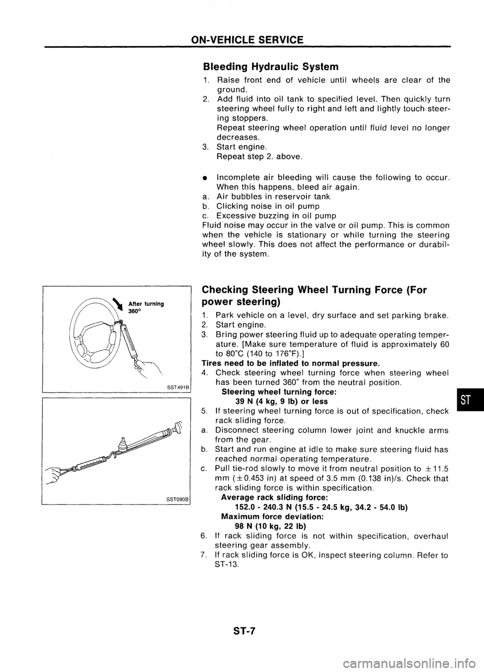
Checking SteeringWheelTurning Force(For
power steering)
1. Park vehicle onalevel, drysurface andsetparking brake.
2. Start engine.
3. Bring power steering fluiduptoadequate operating temper-
ature. [Make suretemperature offluid isapproximately 60
to 80°C (140to176°F).]
Tires needtobe inflated tonormal pressure.
4. Check steering wheelturning forcewhen steering wheel
has been turned 360°from theneutral position.
Steering wheelturning force: •
39 N(4 kg, 9Ib) orless
5.
If
steering wheelturning forceisout ofspecification, check
rack sliding force.
a. Disconnect steeringcolumnlowerjointandknuckle arms
from thegear.
b. Start andrunengine atidle tomake suresteering fluidhas
reached normaloperating temperature.
c. Pull tie-rod slowlytomove itfrom neutral position to
::l::
11.5
mm
(::l::
0.453 in)atspeed of3.5 mm (0.138 in)/s.Check that
rack sliding forceiswithin specification.
Average racksliding force:
152.0 -240.3 N(15.5 -24.5 kg,34.2 -54.0 Ib)
Maximum forcedeviation:
98 N(10 kg, 22Ib)
6.
If
rack sliding forceisnot within specification, overhaul
steering gearassembly.
7. Ifrack sliding forceisOK, inspect steering column.Referto
ST-13.
ST-7
Page 1674 of 1701
ST27091000
.. :Direction ofoil flow Low-pressure
hose SST834-AON-VEHICLE
SERVICE
Checking Hydraulic System
Before starting, checkbelttension, drivingpulleyandtirepres-
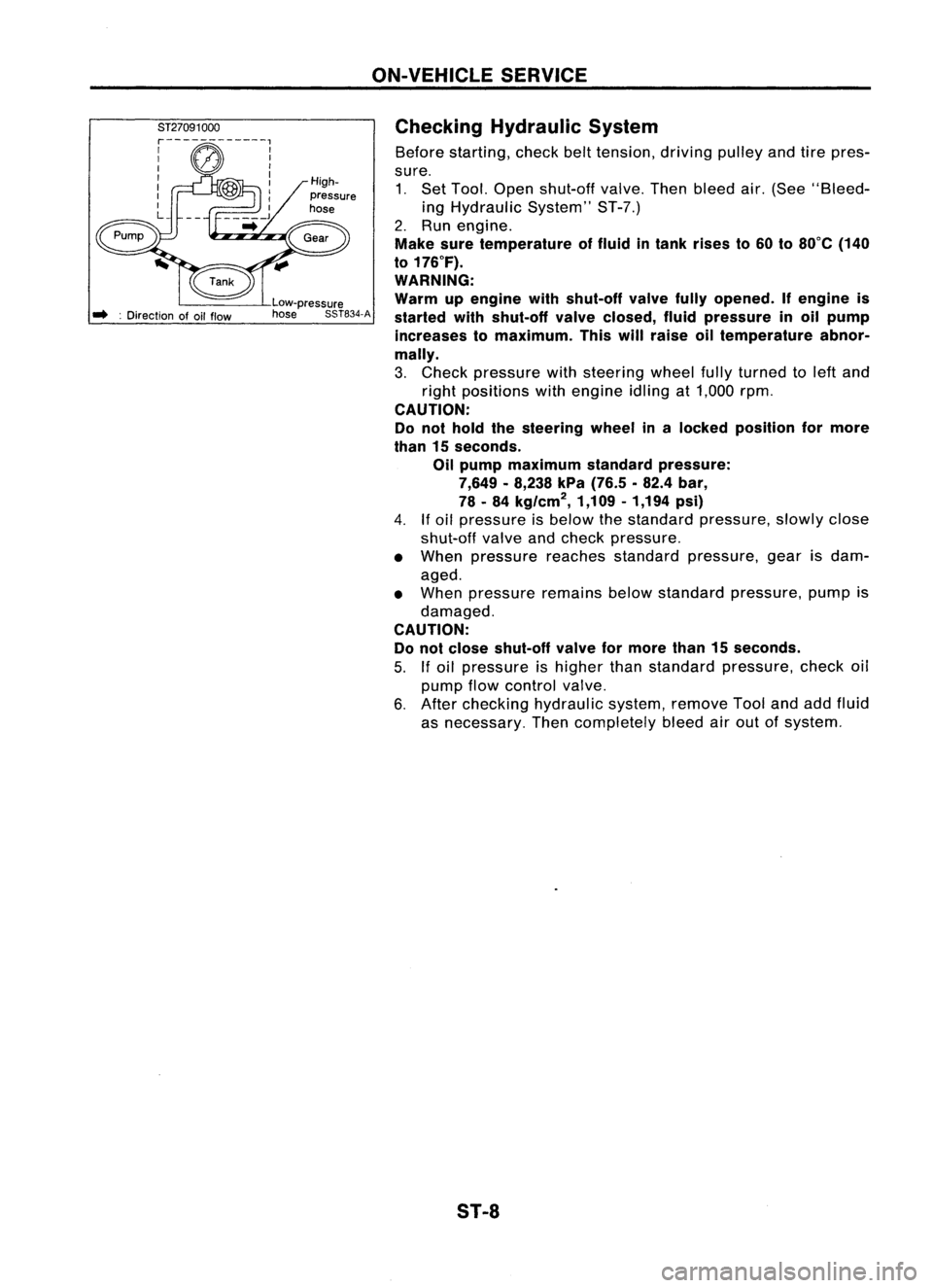
sure. 1. Set Tool. Open shut-off valve.Thenbleed air.(See "Bleed-
ing Hydraulic System"ST-7.)
2. Run engine.
Make suretemperature offluid intank rises to60 to80°C (140
to 176°F).
WARNING:
Warm upengine withshut-off valvefullyopened. Ifengine is
started withshut-off valveclosed, fluidpressure inoil pump
increases tomaximum. Thiswillraise oiltemperature abnor-
mally.
3. Check pressure withsteering wheelfullyturned toleft and
right positions withengine idlingat1,000 rpm.
CAUTION:
Do not hold thesteering wheelinalocked position formore
than 15seconds.
Oil pump maximum standardpressure:
7,649 -8,238 kPa(76.5 .82.4 bar,
78 -84 kg/cm
2,
1,109-1,194 psi)
4.
If
oil pressure isbelow thestandard pressure, slowlyclose
shut-off valveandcheck pressure.
• When pressure reachesstandard pressure, gearisdam-
aged.
• When pressure remainsbelowstandard pressure, pumpis
damaged.
CAUTION: Do not close shut-off valveformore than15seconds.
5.
If
oil pressure ishigher thanstandard pressure, checkoil
pump flowcontrol valve.
6. After checking hydraulic system,removeToolandaddfluid
as necessary. Thencompletely bleedairout ofsystem.
S1-8
Page 1688 of 1701
POWERSTEERING GEARANDLINKAGE (ModelPR24AC)
Disassembly
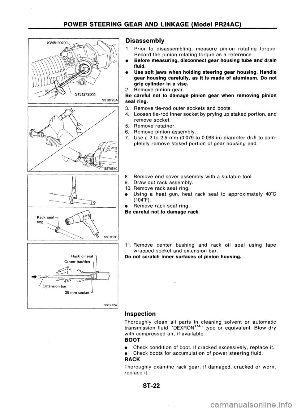
1. Prior todisassembling, measurepinionrotating torque.
Record thepinion rotating torqueasareference.
• Before measuring, disconnectgearhousing tubeanddrain
fluid.
• Use softjaws when holding steering gearhousing. Handle
gear housing carefully, asitis made ofaluminum. Donot
grip cylinder inavise.
2. Remove piniongear.
Be careful nottodamage piniongearwhen removing pinion
seal ring.
3. Remove tie-rodoutersockets andboots.
4. Loosen tie-rodinnersocket byprying upstaked portion, and
remove socket.
5. Remove retainer.
6. Remove pinionassembly.
7. Use a2to 2.5 mm (0.079 to0.098 in)diameter drilltocom-
pletely remove stakedportion ofgear housing end.
8. Remove endcover assembly withasuitable tool.
9. Draw outrack assembly.
10. Remove rackseal ring.
• Using aheat gun,heat racksealtoapproximately 40°C
(104°F).
• Remove racksealring.
Be careful nottodamage rack.
11. Remove centerbushing andrack oilseal using tape
wrapped socketandextension bar.
Do not scratch innersurfaces ofpinion housing .
.. !tension bar
29 mm socket
SST472AInspection
Thoroughly cleanallparts incleaning solventorautomatic
transmission fluid''DEXRON™,, typeorequivalent. Blowdry
with compressed air,ifavailable.
BOOT
• Check condition ofboot. Ifcracked excessively, replaceit.
• Check bootsforaccumulation ofpower steering fluid.
RACK
Thoroughly examinerackgear. Ifdamaged, crackedorworn,
replace it.
ST-22
Page 1689 of 1701
POWERSTEERING GEARANDLINKAGE (ModelPR24AC)
Inspection (Cont'd)
PINION ASSEMBLY
• Thoroughly examinepiniongear.Ifpinion gearisdamaged,
cracked orworn, replace it.
• Check thatallbearings rollfreely. Ensure thatballs, rollers
and races arenotcracked, pittedorworn. Replace ifnec-
essary.
GEAR HOUSING CYLINDER
Check gearhousing cylinder boreforscratches orother dam-
age. Replace ifnecessary.
SST083B
•
2.
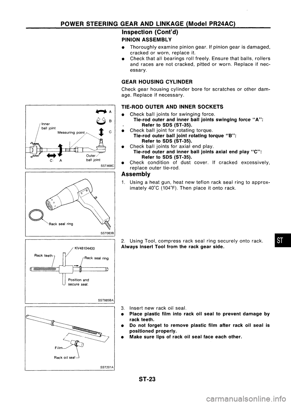
Using Tool,compress rackseal ringsecurely ontorack.
Always insertToolfrom therack gear side.
TIE-ROD
OUTERANDINNER SOCKETS
• Check balljoints forswinging force.
Tie-rod outerandinner ball
joints
swinging force
"A":
Refer toSOS (ST-35).
• Check balljoint forrotating torque.
Tie-rod outerballjoint rotating torque
"B":
Refer to50S (ST-35).
• Check balljoints foraxial endplay.
Tie-rod outerandinner balljoints axialendplay
"e":
Refer to50S (ST-35).
• Check condition ofdust cover. Ifcracked excessively,
replace outertie-rod.
Assembly
1. Using aheat gun,heat newteflon rackseal ringtoapprox-
imately 40°C(104°F). Thenplace
it
onto rack.
Us
Rack sealring
Inner
ball joint
+
Measuring pOin;~~
+
C
/'
~R"k ,.. I
""9
Position and
secure seal.
SST885BA
c--.~
~
Film
Rack oilseal 3.
Insert newrack oilseal.
• Place plastic filmintorack oilseal toprevent damage by
rack teeth.
• Donot forget toremove plasticfilmafter rackoilseal is
positioned properly.
• Make surelipsofrack oilseal face each other.
SST201A ST-23