1995 NISSAN ALMERA N15 wheel
[x] Cancel search: wheelPage 803 of 1701
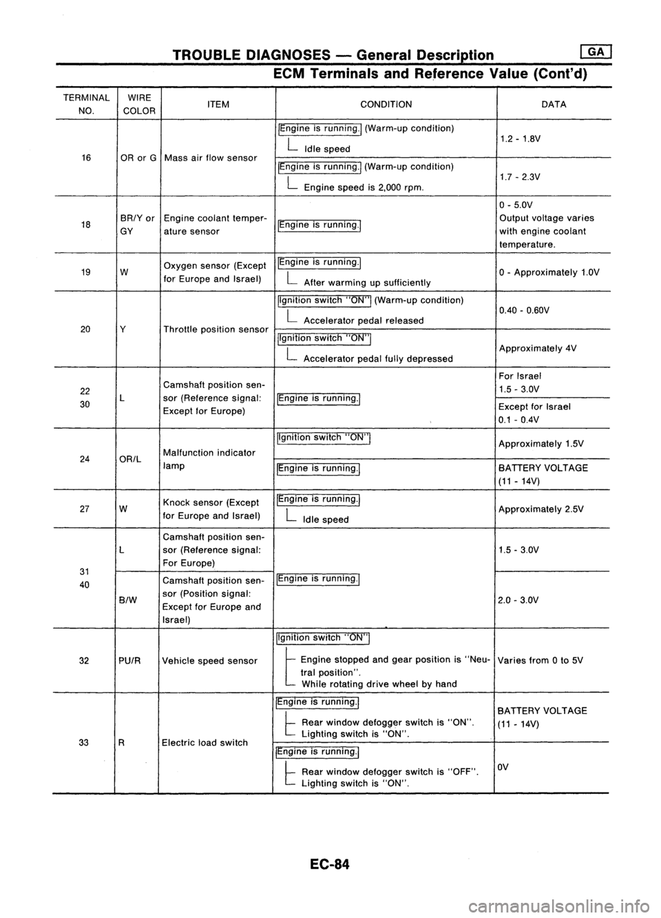
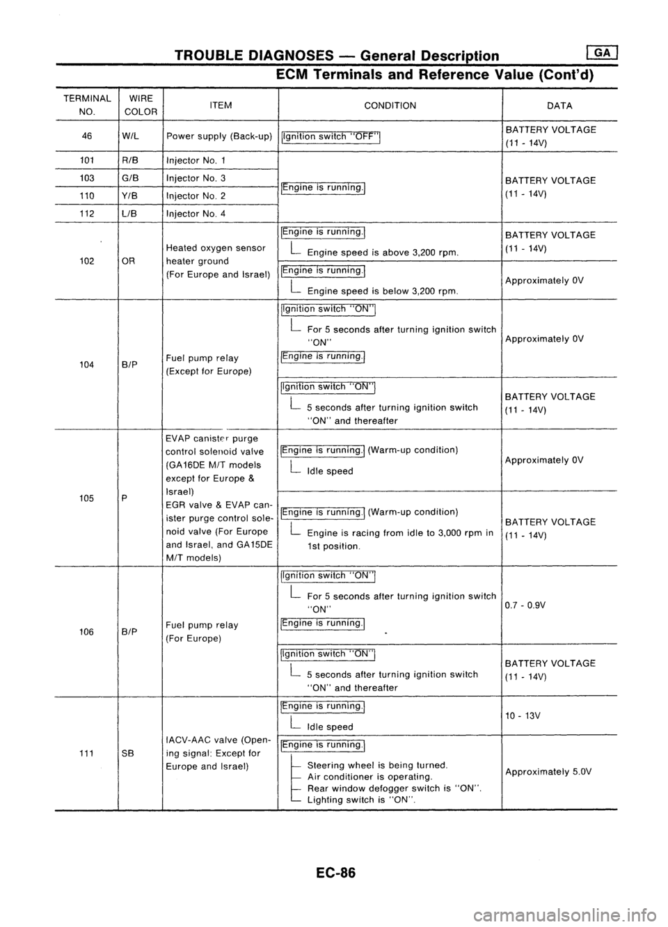
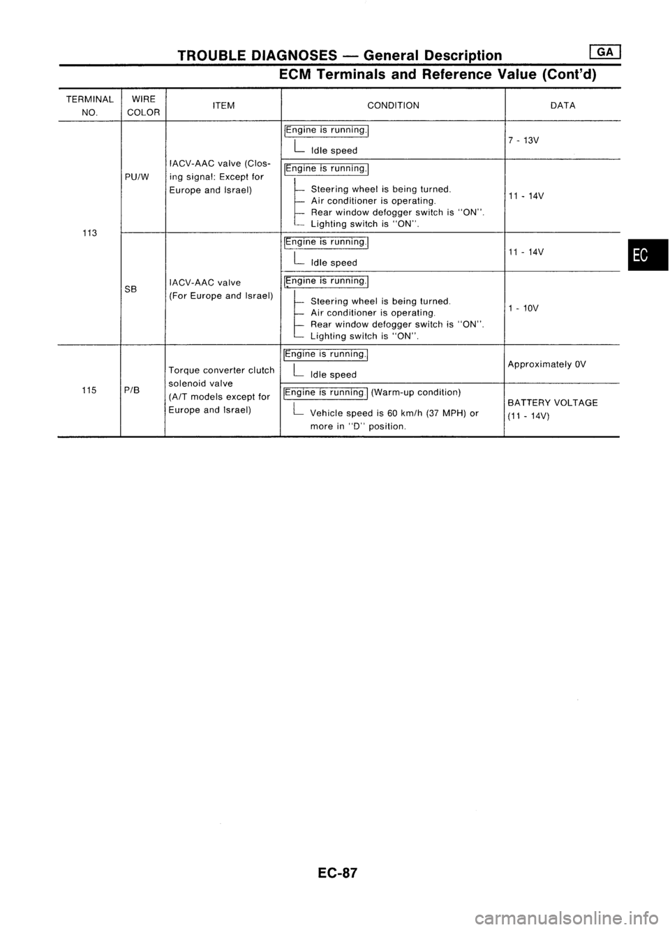
TROUBLEDIAGNOSES -General Description
rnJ
ECM Terminals andReference Value(Cont'd)
TERMINAL WIRE
CONDITION
NO. COLOR ITEM
DATA
IEngine isrunning./ (Warm-up condition)
1.2-1.8V
L
Idle speed
16 ORorG Mass airflow sensor
IEngineisrunning.1 (Warm-up condition)
1.7-2.3V
L
Engine speedis2,000 rpm.
0-5.0V
18 BR/Yor
Enginecoolant temper-
IEngineisrunning.' Output
voltage varies
GY aturesensor with
engine coolant
temperature.
19 W Oxygen
sensor(Except IEngine
isrunning.1
o-
Approximately 1.0V
for Europe andIsrael)
L
After warming upsufficiently
Ilgnition switch"ON"I(Warm-up condition)
0.40-0.60V
L
Accelerator pedalreleased
20 Y Throttlepositionsensor
jlgnitionswitch"ON"I
L
Accelerator pedalfullydepressed Approximately
4V
For Israel
22 Camshaft
positionsen-
1.5-3.0V
30 L
sor(Reference signal:
IEngineisrunning.1
Except forEurope) Except
forIsrael
0.1 -0.4V
Ilgnition switch"ON'"
Approximately1.5V
24 ORIL Malfunction
indicator
lamp IEngineisrunning.1 BATIERY
VOLTAGE
(11 -14V)
27 W Knock
sensor (Except IEngine
isrunning.1
Approximately2.5V
for Europe andIsrael)
L
Idle speed
Camshaft positionsen-
L sor(Reference signal: 1.5-3.0V
For Europe)
31 IEngineisrunning.1
40 Camshaft
positionsen-
B/W
sor
(Position signal:
2.0-3.0V
Except forEurope and
Israel)
Ilgnitionswitch"ON"I
32 PUIR Vehiclespeedsensor
t
Eog'oe stopped aodgea, posit;oo
'S
"Neu- Variesfrom0to 5V
tral position".
While rotating drivewheel byhand
IEngine isrunning.1
BATIERY VOLTAGE
t
Rear window defogger switchis"ON".
(11-14V)
Electric loadswitch Lighting
switchis"ON".
33 R
IEngineisrunning.1
t
Rear window defogger switchis"OFF". OV
Lighting switchis"ON".
EC-84
Page 804 of 1701
![NISSAN ALMERA N15 1995 Service Manual TROUBLEDIAGNOSES -General Description @K]
ECM Terminals andReference Value(Conl'd)
TERMINAL WIRE
NO. COLOR ITEM
CONDITION
DATA
Ilgnition switch"ON"I
ApproximatelyOV
34 BIY Startsignal
pgn NISSAN ALMERA N15 1995 Service Manual TROUBLEDIAGNOSES -General Description @K]
ECM Terminals andReference Value(Conl'd)
TERMINAL WIRE
NO. COLOR ITEM
CONDITION
DATA
Ilgnition switch"ON"I
ApproximatelyOV
34 BIY Startsignal
pgn](/manual-img/5/57349/w960_57349-803.png)
TROUBLEDIAGNOSES -General Description @K]
ECM Terminals andReference Value(Conl'd)
TERMINAL WIRE
NO. COLOR ITEM
CONDITION
DATA
Ilgnition switch"ON"I
ApproximatelyOV
34 BIY Startsignal
pgnitionswitch"START"I BATTERY
VOLTAGE
(11 -14V)
pgnition switch"ON"I
t
"N" or"P" position
(A/T)
OV
Neutral position
(M/T)
Neutral position switchl For
Europe andIsrael
35
G/OR
Approximately5V
Inhibitor switch
llgnitionswitch"ON"1
ExceptforEurope and
. L
Except theabove gearposition Israel
BATTERY VOLTAGE
(11 -14V)
Ilgnition switch"OFF"!
OV
36 B/R Ignition
switch(Except
for Europe)
!Ignitionswitch"ON"I BA
TTERY VOLTAGE
(11 •14V)
37 P/L Throttle
position sensor
Ilgnitionswitch"ON"I
Approximately5V
power supply
38
W/R
Powersupply forECM Ilgnition switch"ON"I BA
TTERY VOLTAGE
47 (11
-14V)
IEngine isrunning.1
L
Both airconditioner switchandblower Approximately
OV
41 Gor GY Air
conditioner switch fan
switch are"ON".
!Engine isrunning.1
BATTERYVOLTAGE
L
Airconditioner switchis"OFF". (11
-14V)
IEngine isrunning.!
OV
PU/W Power
steering oilpres-
L
Steering wheelisbeing turned.
43 sureswitch
IEngineisrunning.1
L
Steering wheelisnot being turned. Approximately
5V
jlgnition switch"OFF"I OV
Ignition switch
44 B/R
(ForEurope) BA
TTERY VOLTAGE
pgnition switch"ON"I
(11-14V)
IEngine isrunning.1
Thermo controlamp.
L
Both airconditioner switchandblower fanApproximately
OV
44 R/L (Except
forEurope and switch
are"ON".
Israel) IEngineisrunning.1
BATTERYVOLTAGE
L
Airconditioner switchis"OFF". (11
-14V)
IEngine isrunning.1
ApproximatelyOV
L
Blower fanswitch is"ON".
45 LG/B
or
Blower fanswitch
G/Y
IEngineisrunning.!
L
Blower fanswitch is"OFF". Approximately
5V
EC-85
•
Page 805 of 1701
TROUBLEDIAGNOSES -General Description
mJ
ECM Terminals andReference Value(Cont'd)
TERMINAL WIRE
NO. COLOR ITEM
CONDITION DATA
46 WIL Powersupply (Back-up)
Ilgnitionswitch"OFF'" BA
TTERY VOLTAGE
(11 -14V)
101 RIB InjectorNo.1
103
GIB
InjectorNo.3
BATTERYVOLTAGE
110 Y/B InjectorNO.2 IEngine
isrunning./
(11-14V)
112 LIB Injector
NO.4
IEngineisrunning.1
BATTERY VOLTAGE
Heated oxygen sensor
L
Engine speedisabove 3,200rpm. (11
-14V)
102 OR heaterground
(For Europe andIsrael) IEngine
isrunning.1
ApproximatelyOV
L
Engine speedisbelow 3,200rpm.
jlgnition switch"ON"I
L
For 5seconds afterturning ignition switch
"ON" Approximately
OV
104 B/P Fuel
pump relay /Engine
isrunning.1
(Except forEurope)
Ilgnitionswitch"ON"I
BATTERYVOLTAGE
L
5seconds afterturning ignition switch
(11-14V)
"ON" andthereafter
EVAP canister purge
control solenoid valveIEngine
isrunning.1 (Warm-up condition)
(GA16DE
MIT
models
L
Idle speed Approximately
OV
except forEurope
&
105 P Israel)
EGR valve
&
EVAP can-
ister purge control sole-IEngine
isrunning.1 (Warm-up condition)
BATTERYVOLTAGE
noid valve (ForEurope
L
Engine isracing fromidleto3,000 rpmin
(11-14V)
and Israel, andGA15DE
1st position.
MIT
models)
jlgnitionswitch"ON"I
L
For 5seconds afterturning ignition switch
"ON" 0.7
-0.9V
106 SIP Fuel
pump relay IEngine
isrunning.1
(For Europe)
-
Ilgnition switch"ON"I
BATTERYVOLTAGE
L
5seconds afterturning ignition switch
(11-14V)
"ON" andthereafter
IEngine isrunning.1
10-13V
L
Idle speed
IACV-AAC valve(Open-
IEngineisrunning.1
111 5B ingsignal: Exceptfor
Europe andIsrael)
l
51.."" wheel
t,
be'" I,med
Approximately5.0V
Air conditioner isoperating.
Rear window defogger switchis"ON".
Lighting switchis"ON".
EC-86
Page 806 of 1701
TROUBLEDIAGNOSES -General Description
[ill
ECM Terminals andReference Value(Cont'd)
TERMINAL WIRE
ITEM CONDITION
DATA
NO. COLOR
IEngineisrunning.1
7-13V
L
Idle speed
IACV-AAC valve(Clos-
~gineisrunning.1
PU/W ing
signal: Exceptfor
Europe andIsrael)
t
Stee,'", wheel',be'",t,med
11-14V
Air conditioner isoperating.
Rear window defogger switchis"ON".
Lighting switchis"ON".
113 IEngineisrunning.1
11-14V
L
Idle speed
5B IACV-AAC
valve I~ngine
isrunning.1
(For Europe andIsrael)
~Steee'", wheel"be'", t,med
Air conditioner isoperating. 1
-10V
Rear window defogger switchis"ON".
Lighting switchis"ON".
IEngine isrunning.1
ApproximatelyOV
Torque converter clutch
L
Idle speed
solenoid valve
115 P/B
(A/T
models exceptforIEngine
isrunning
I
(Warm-up condition)
L
BATTERY
VOLTAGE
Europe andIsrael)
Vehiclespeedis60 km/h (37MPH) or
(11-14V)
more in
"0"
position.
EC-87
•
Page 855 of 1701
TROUBLEDIAGNOSIS FORNON-DETECTABLE ITEMS
@!J
Vehicle SpeedSensor (VSS)(Conl'd)
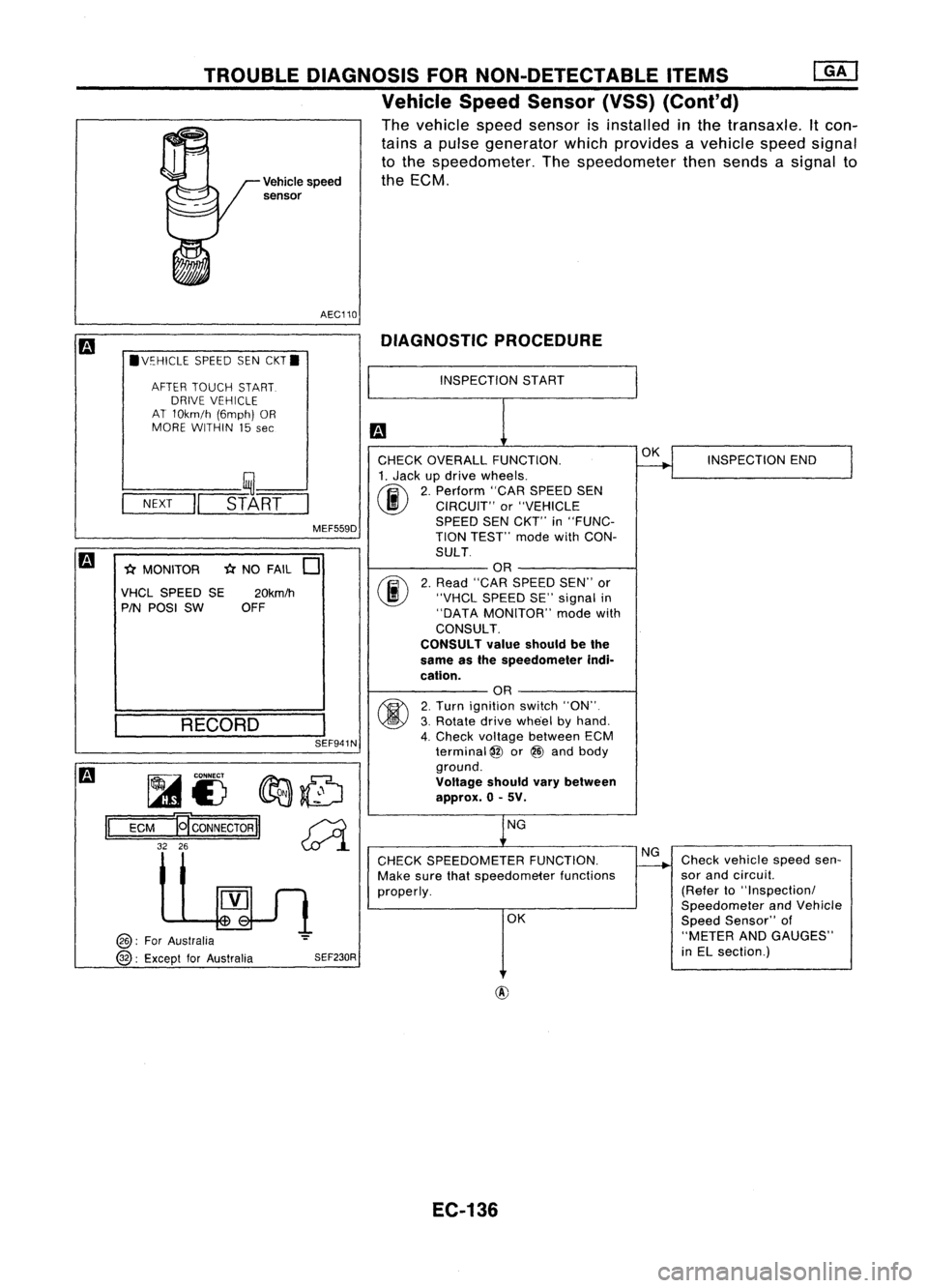
The vehicle speedsensor isinstalled inthe transaxle. Itcon-
tains apulse generator whichprovides avehicle speedsignal
to the speedometer. Thespeedometer thensends asignal to
Vehicle speed theECM.
sensor
AEC110 DIAGNOSTIC PROCEDURE
.V~HICLE SPEEDSENCKT.
AFTER TOUCH START.
DRIVE VEHICLE
AT 10km/h (6mph)OR
MORE WITHIN 15
see
INSPECTION
START
SEF941N
-(;(
NO FAIL
0
fijf.....
CONNECT
fIr:J:J:.~
1A1£) ~~
ECM
19'
CONNECTOR
II~
32 26
~l
INSPECTION
END
Check vehicle speedsen-
sor and circuil.
(Refer to"Inspectionl
Speedometer andVehicle
Speed Sensor" of
"METER ANDGAUGES"
in EL section.)
OK
NG
OK
NG
CHECK SPEEDOMETER FUNCTION.
Make surethatspeedometer functions
properly.
CHECK
OVERALL FUNCTION.
1. Jack updrive wheels.
(ij\
2.Perform "CARSPEED SEN
~ CIRCUIT" or"VEHICLE
SPEED SENCKT'" in"FUNC-
TION TEST'" modewithCON-
SULT OR
2. Read "CAR SPEED SEN"'or
"VHCL SPEED SE"signal in
"DATA MONITOR" modewith
CONSULT.
CONSULT valueshould bethe
same asthe speedometer indi-
cation. OR
2. Turn ignition switch"ON".
3. Rotate drivewhe'el byhand.
4. Check voltage between ECM
terminal
@
or@ and body
ground.
Voltage shouldvarybetween
approx. 0-5V.
SEF230R
MEF559D
20km/h
OFF
RECORD
l----
__ ,~--'
-N-EX-T
-II
STA-RT-
-(;( MONITOR
VHCL SPEED SE
PIN POSI SW
@:
ForAustralia
@:
Except forAustralia
II
EC-136
Page 890 of 1701

•
INSPECTION END
OK
The
power steering oilpressure switchisattached tothe power
steering high-pressure tubeanddetects apower steering load.
When apower steering loadisdetected,
it
signals theECM. The
ECM adjusts theIACV-AAC valvetoincrease theidle speed and
adjust forthe increased load.
INSPECTION START
OR
1. Start engine.
2. Check voltage between ECM
terminal
@
or
@
and ground.
Voltage: When steering wheelis
turned quickly.
Approximately OV
Except above
Approximately 5V
NG
DIAGNOSTIC
PROCEDURE
CHECK OVERALL FUNCTION.
fiii\
1.Turn ignition switch"ON".
~ 2.Perform "PW/STSIGNAL
CIRCUIT" in"FUNCTION
TEST" modewithCONSULT.
OR
(F.i\
1.Start engine.
~ 2.Check "PW/ST SIGNAL" in
"DATA MONITOR" modewith
CONSULT.
Steering isin neutral
position: OFF
Steering isturned:
ON
SEF591I
SEF235R
MEF023E
Power
steering oil___
pressure switch
-
~
to
TROUBLE
DIAGNOSIS FORNON-DETECTABLE ITEMS
@[]
Power Steering OilPressure Switch(Cont'd)
COMPONENT DESCRIPTION
RECORD
NEXT
II
START
•
PW/ST SIGNAL CIRCUIT.
HOLD STEERING WHEEL
IN AFULL
LOCKED
POSITION
THEN
TOUCH START
* MONITOR *NO FAIL
0
PW/ST SIGNAL OFF
@):
ForAustralia
@:
Except forAustralia
~i)~
II
ECM
Ef
CONNECTOR
II
43 25
EC-171
Page 891 of 1701
![NISSAN ALMERA N15 1995 Service Manual TROUBLEDIAGNOSIS FORNON-DETECTABLE ITEMS
@K]
Power Steering OilPressure Switch(Cont'd)
@:
ForAustralia
@:
Except forAustralia SEF176R
Repair
harness orcon-
nectors.
CHECK INPUTSIGNAL CIRCUIT. NISSAN ALMERA N15 1995 Service Manual TROUBLEDIAGNOSIS FORNON-DETECTABLE ITEMS
@K]
Power Steering OilPressure Switch(Cont'd)
@:
ForAustralia
@:
Except forAustralia SEF176R
Repair
harness orcon-
nectors.
CHECK INPUTSIGNAL CIRCUIT.](/manual-img/5/57349/w960_57349-890.png)
TROUBLEDIAGNOSIS FORNON-DETECTABLE ITEMS
@K]
Power Steering OilPressure Switch(Cont'd)
@:
ForAustralia
@:
Except forAustralia SEF176R
Repair
harness orcon-
nectors.
CHECK INPUTSIGNAL CIRCUIT. NG
Check thefollowing .
1. Disconnect ECMharness connector.
......---..
•Harness connectors
2. Check harness continuity between
aD,
(MID
ECM terminal
@
or
@
and terminal •
Harness connectors
G).
@,@or@,
Continuity shouldexist.
If
OK, check harness forshort. •
Harness foropen or
OK short
between ECMand
power steering oilpres-
sure switch
If NG, repair harness or
connectors.
CHECK COMPONENT NG
Replace powersteering
(Power steering oilpressure switch).
--...
oilpressure switch.
Refer to"COMPONENT INSPECTION"
below.
OK
Disconnect andreconnect harnesscon-
nectors inthe circuit. Thenretest.
Trouble isnot fixed.
Check ECMpinterminals fordamage or
the connection ofECM harness connec-
tor. Reconnect ECMharness connector
and retest.
@
1
CHECK GROUND CIRCUIT.
1. Turn ignition switch"OFF".
2. Disconnect powersteering oilpres-
sure switch harness connector.
3. Check harness continuity between
terminal
@
and engine ground.
Continuity shouldexist.
AEC760
IfOK, check harness forshort.
~i5
[i
c:ITb
~i5
ECM
Ef
CONNECTOR
II
43 25
II
INSPECTIONEND
Power steering oilpressure switch
1. Disconnect powersteering oilpressure switchharness con-
nector thenstart engine.
2. Check continuity betweenterminals
@.
[At
IV
ID
~ COMPONENT
INSPECTION
Conditions
Steering wheelisbeing turned
Steering wheelisnot being turned Continuity
Yes
No
AEC762
IfNG, replace powersteering oilpressure switch.
EC-172
Page 900 of 1701
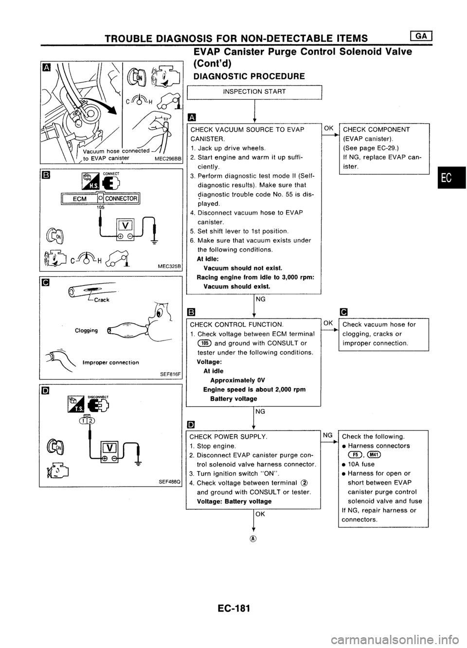
•
INSPECTION
START
m
CHECK VACUUM SOURCETOEVAP OK
CHECK COMPONENT
CANISTER.
L---.
(EVAPcanister).
1. Jack updrive wheels. (See
page EC-29.)
2. Start engine andwarm itup suffi- If
NG, replace EVAPcan-
ciently. ister.
3. Perform diagnostic testmode II(Self-
diagnostic results).Makesurethat
9iagnostic troublecodeNo.55isdis-
played.
4. Disconnect vacuumhosetoEVAP
canister.
5. Set shift lever to1st position.
6. Make surethatvacuum existsunder
the following conditions.
At Idle:
Vacuum shouldnotexist.
Racing enginefromIdleto3,000 rpm:
Vacuum shouldexist.
NG
Ii)
[!J
CHECK CONTROL FUNCTION. OK
Check vacuum hosefor
1. Check voltage between ECMterminal
--..
clogging, cracksor
@
andground withCONSULTor improperconnection.
tester underthefollowing conditions.
Voltage: At idle
Approximately OV
Engine speedisabout 2,000rpm
Battery voltage
NG
I!l
CHECK POWER SUPPLY. NG
Check thefollowing.
1. Stop engine.
I-----.
•Harness connectors
2. Disconnect EVAPcanister purgecon-
QD,@
trol solenoid valveharness connector. •10A fuse
3. Turn ignition switch"ON". •
Harness foropen or
4. Check voltage between terminal
@
short
between EVAP
and ground withCONSULTor tester. canister
purgecontrol
Voltage: Batteryvoltage
solenoid
valveandfuse
r
K If
NG, repair harness or
connectors.
SEF816F
SEF488Q
MEC325B
MEC296BB
Clogging TROUBLE
DIAGNOSIS FORNON-DETECTABLE ITEMS
[ill
EVAP Canister PurgeControl Solenoid Valve
(Cont'd)
DIAGNOSTIC PROCEDURE
~i5
ECM
B
CONNECTOR
II
'f
~VV1
~ Crack
~i5
~
=:5---
~ Improperconnection
@
EC-181