Page 1617 of 2198
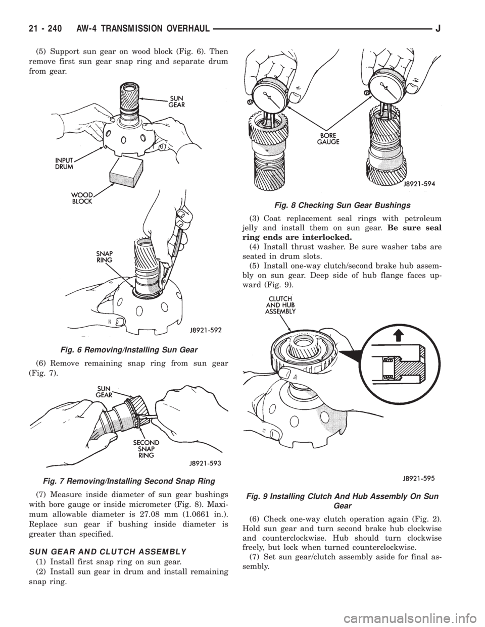
(5) Support sun gear on wood block (Fig. 6). Then
remove first sun gear snap ring and separate drum
from gear.
(6) Remove remaining snap ring from sun gear
(Fig. 7).
(7) Measure inside diameter of sun gear bushings
with bore gauge or inside micrometer (Fig. 8). Maxi-
mum allowable diameter is 27.08 mm (1.0661 in.).
Replace sun gear if bushing inside diameter is
greater than specified.
SUN GEAR AND CLUTCH ASSEMBLY
(1) Install first snap ring on sun gear.
(2) Install sun gear in drum and install remaining
snap ring.(3) Coat replacement seal rings with petroleum
jelly and install them on sun gear.Be sure seal
ring ends are interlocked.
(4) Install thrust washer. Be sure washer tabs are
seated in drum slots.
(5) Install one-way clutch/second brake hub assem-
bly on sun gear. Deep side of hub flange faces up-
ward (Fig. 9).
(6) Check one-way clutch operation again (Fig. 2).
Hold sun gear and turn second brake hub clockwise
and counterclockwise. Hub should turn clockwise
freely, but lock when turned counterclockwise.
(7) Set sun gear/clutch assembly aside for final as-
sembly.
Fig. 6 Removing/Installing Sun Gear
Fig. 7 Removing/Installing Second Snap Ring
Fig. 8 Checking Sun Gear Bushings
Fig. 9 Installing Clutch And Hub Assembly On Sun
Gear
21 - 240 AW-4 TRANSMISSION OVERHAULJ
Page 1629 of 2198
REMOVING UPPER BODY FROM LOWER BODY
(1) Remove two-piece detent spring (Fig. 3). Note
position of spring sections for assembly reference.
(2) Remove manual valve from lower body (Fig. 4).
(3) Remove bolts attaching upper body to lower
body (Fig. 5).
(4) Carefully lift and remove upper body, plate and
gaskets from lower body (Fig. 6).
(5) Disassemble and overhaul upper and lower
body sections as outlined in following procedures.
LOWER BODY DISASSEMBLY
(1) Remove check valve and spring, pressure relief
valve and spring and ball check and seat from lower
body. Note location of each valve for assembly refer-
ence (Fig. 1).
Fig. 3 Removing/Installing Detent Spring
Fig. 4 Removing/Installing Manual Valve
Fig. 5 Valve Body Bolt Locations
Fig. 6 Upper Body, Plate And Gaskets
Fig. 1 Lower Body Check Valve And Strainer
Location
21 - 252 AW-4 TRANSMISSION OVERHAULJ
Page 1631 of 2198
use shop towels or rags. Lint or foreign material from
towels or rags can interfere with valve operation.
(13) Inspect condition of lower body components.
Replace lower body if any bores are scored or cor-
roded. Replace valves, plugs or sleeves that are
scored or worn. Replace oil strainers if cut, torn or
damaged in any way.
(14) Inspect valve body springs. Replace any spring
having rusted, distorted, or collapsed coils. Measure
length of each valve body spring. Replace any spring
if free length is less than length specified in following
chart (Fig. 11).
LOWER BODY ASSEMBLY
(1) Lubricate lower body components with auto-
matic transmission fluid.
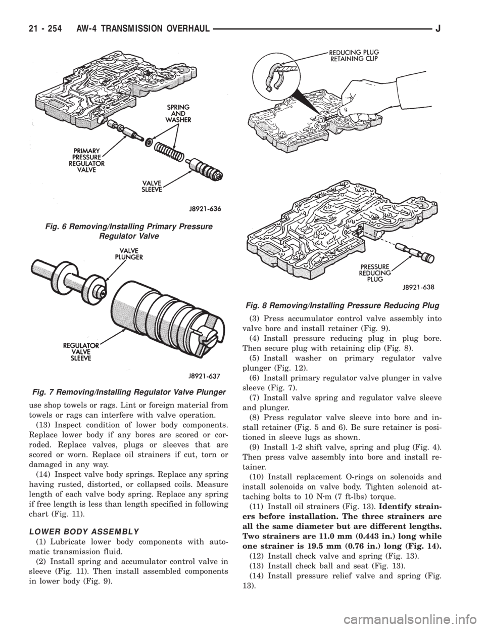
(2) Install spring and accumulator control valve in
sleeve (Fig. 11). Then install assembled components
in lower body (Fig. 9).(3) Press accumulator control valve assembly into
valve bore and install retainer (Fig. 9).
(4) Install pressure reducing plug in plug bore.
Then secure plug with retaining clip (Fig. 8).
(5) Install washer on primary regulator valve
plunger (Fig. 12).
(6) Install primary regulator valve plunger in valve
sleeve (Fig. 7).
(7) Install valve spring and regulator valve sleeve
and plunger.
(8) Press regulator valve sleeve into bore and in-
stall retainer (Fig. 5 and 6). Be sure retainer is posi-
tioned in sleeve lugs as shown.
(9) Install 1-2 shift valve, spring and plug (Fig. 4).
Then press valve assembly into bore and install re-
tainer.
(10) Install replacement O-rings on solenoids and
install solenoids on valve body. Tighten solenoid at-
taching bolts to 10 Nzm (7 ft-lbs) torque.
(11) Install oil strainers (Fig. 13).Identify strain-
ers before installation. The three strainers are
all the same diameter but are different lengths.
Two strainers are 11.0 mm (0.443 in.) long while
one strainer is 19.5 mm (0.76 in.) long (Fig. 14).
(12) Install check valve and spring (Fig. 13).
(13) Install check ball and seat (Fig. 13).
(14) Install pressure relief valve and spring (Fig.
13).
Fig. 6 Removing/Installing Primary Pressure
Regulator Valve
Fig. 7 Removing/Installing Regulator Valve Plunger
Fig. 8 Removing/Installing Pressure Reducing Plug
21 - 254 AW-4 TRANSMISSION OVERHAULJ
Page 1638 of 2198
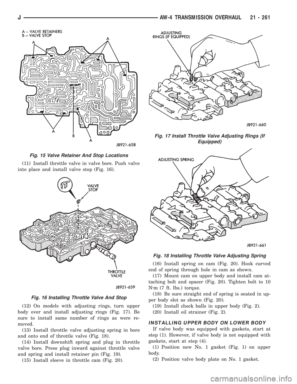
(11) Install throttle valve in valve bore. Push valve
into place and install valve stop (Fig. 16).
(12) On models with adjusting rings, turn upper
body over and install adjusting rings (Fig. 17). Be
sure to install same number of rings as were re-
moved.
(13) Install throttle valve adjusting spring in bore
and onto end of throttle valve (Fig. 18).
(14) Install downshift spring and plug in throttle
valve bore. Press plug inward against throttle valve
and spring and install retainer pin (Fig. 19).
(15) Install sleeve in throttle cam (Fig. 20).(16) Install spring on cam (Fig. 20). Hook curved
end of spring through hole in cam as shown.
(17) Mount cam on upper body and install cam at-
taching bolt and spacer (Fig. 20). Tighten bolt to 10
Nzm (7 ft. lbs.) torque.
(18) Be sure straight end of spring is seated in up-
per body slot as shown (Fig. 20).
(19) Install check balls in upper body (Fig. 2).
(20) Install oil strainer (Fig. 2).
INSTALLING UPPER BODY ON LOWER BODY
If valve body was equipped with gaskets, start at
step (1). However, if valve body is not equipped with
gaskets, start at step (4).
(1) Position new No. 1 gasket (Fig. 1) on upper
body.
(2) Position valve body plate on No. 1 gasket.
Fig. 15 Valve Retainer And Stop Locations
Fig. 16 Installing Throttle Valve And Stop
Fig. 17 Install Throttle Valve Adjusting Rings (If
Equipped)
Fig. 18 Installing Throttle Valve Adjusting Spring
JAW-4 TRANSMISSION OVERHAUL 21 - 261
Page 1643 of 2198
(7) Align teeth of second brake drum and clutch
pack (Fig. 4).
(8) Align rear planetary-output shaft assembly
teeth with case slots and install assembly in case
(Fig. 5).(9) Install rear planetary snap ring with snap ring
pliers. Chamfered side of snap ring faces up and to-
ward case front (Fig. 6).
(10) Check first-reverse brake pack clearance with
feeler gauge. Clearance should be 0.70 - 1.20 mm
(0.028 - 0.047 in.). If clearance is incorrect, planetary
assembly, thrust bearing or snap ring is not properly
seated in case. Remove and reinstall components if
necessary.
Fig. 4 Aligning Second Brake Drum And Clutch
Pack Teeth
Fig. 5 Installing Output Shaft And Rear Planetary
Assembly
Fig. 6 Installing Planetary Snap Ring
Fig. 7 Checking First-Reverse Brake Pack Clearance
21 - 266 AW-4 TRANSMISSION OVERHAULJ
Page 1646 of 2198
(21) Check brake pack clearance with feeler gauge
(Fig. 16). Clearance should be 0.062 - 1.98 mm (0.024
- 0.078 in.). If brake pack clearance is not correct,
brake pack components are not seated. Reassemble
brake pack if necessary.
(22) Install planetary sun gear and input drum
(Fig. 17). Be sure drum thrust washer tabs are
seated in drum. Use petroleum jelly to hold thrust
washer in position if necessary.(23) Install front planetary gear on sun gear (Fig.
18).
(24) Support output shaft with wood blocks (Fig.
19).
Fig. 16 Checking Second Brake Pack Clearance
Fig. 17 Installing Sun Gear And Input Drum
Fig. 18 Installing Front Planetary Gear
Fig. 19 Supporting Output Shaft
JAW-4 TRANSMISSION OVERHAUL 21 - 269
Page 1648 of 2198
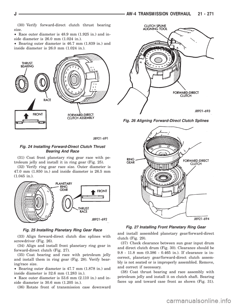
(30) Verify forward-direct clutch thrust bearing
size.
²Race outer diameter is 48.9 mm (1.925 in.) and in-
side diameter is 26.0 mm (1.024 in.).
²Bearing outer diameter is 46.7 mm (1.839 in.) and
inside diameter is 26.0 mm (1.024 in.).
(31) Coat front planetary ring gear race with pe-
troleum jelly and install it in ring gear (Fig. 25).
(32) Verify ring gear race size. Outer diameter is
47.0 mm (1.850 in.) and inside diameter is 26.5 mm
(1.045 in.).
(33) Align forward-direct clutch disc splines with
screwdriver (Fig. 26).
(34) Align and install front planetary ring gear in
forward-direct clutch (Fig. 27).
(35) Coat bearing and race with petroleum jelly
and install them in ring gear (Fig. 28). Verify bear-
ing/race size.
²Bearing outer diameter is 47.7 mm (1.878 in.) and
inside diameter is 32.6 mm (1.283 in.).
²Race outer diameter is 53.6 mm (2.110 in.) and in-
side diameter is 30.6 mm (1.205 in.).
(36) Rotate front of transmission case downwardand install assembled planetary gear/forward-direct
clutch (Fig. 29).
(37) Check clearance between sun gear input drum
and direct clutch drum (Fig. 30). Clearance should be
9.8 - 11.8 mm (0.386 - 0.465 in.). If clearance is in-
correct, planetary gear/forward-direct clutch assem-
bly is not seated or is improperly assembled. Remove,
and correct if necessary.
(38) Coat thrust bearing and race assembly with
petroleum jelly and install it on clutch shaft. Bearing
faces up and toward case front as shown (Fig. 31).
Fig. 24 Installing Forward-Direct Clutch Thrust
Bearing And Race
Fig. 25 Installing Planetary Ring Gear Race
Fig. 26 Aligning Forward-Direct Clutch Splines
Fig. 27 Installing Front Planetary Ring Gear
JAW-4 TRANSMISSION OVERHAUL 21 - 271
Page 1649 of 2198
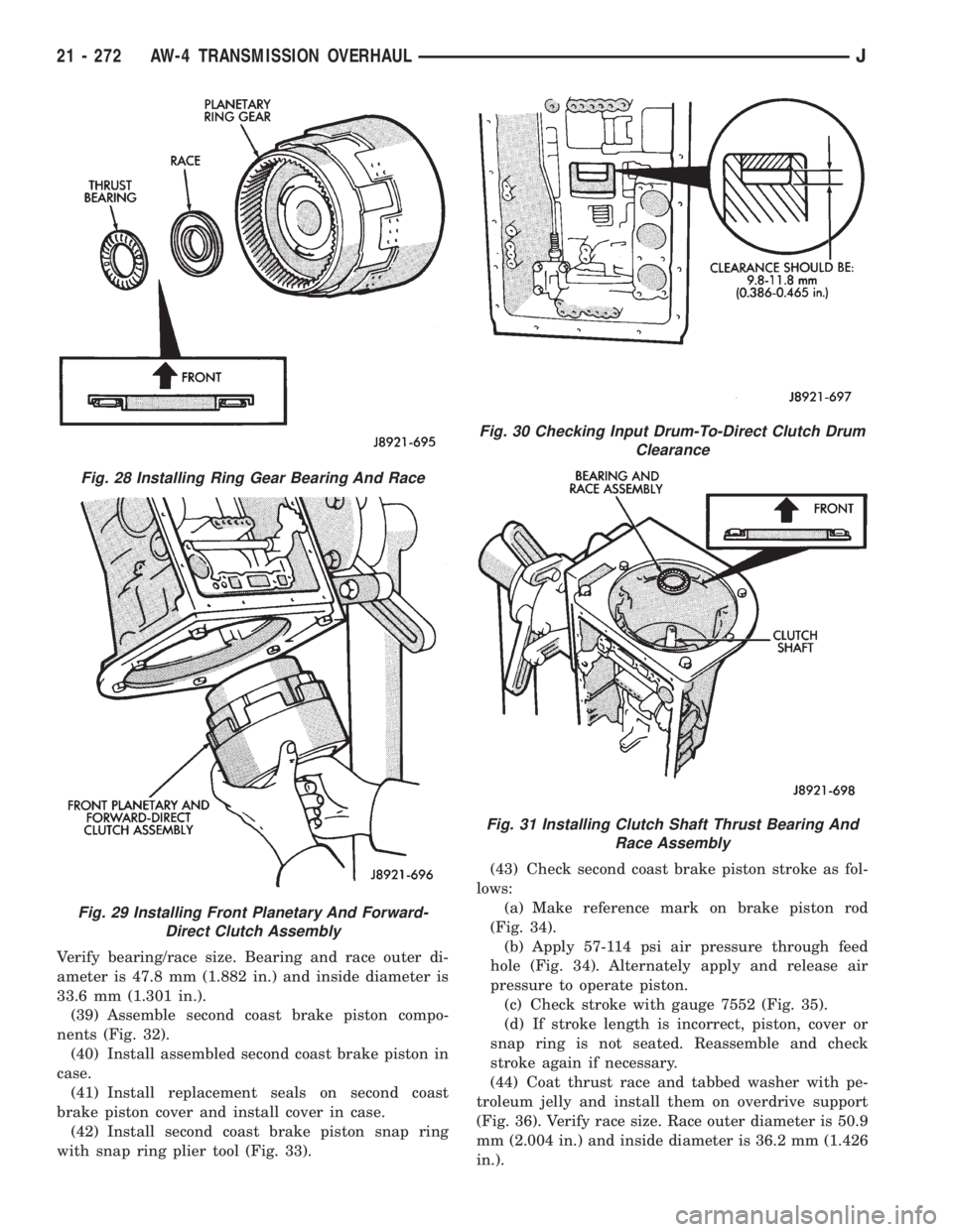
Verify bearing/race size. Bearing and race outer di-
ameter is 47.8 mm (1.882 in.) and inside diameter is
33.6 mm (1.301 in.).
(39) Assemble second coast brake piston compo-
nents (Fig. 32).
(40) Install assembled second coast brake piston in
case.
(41) Install replacement seals on second coast
brake piston cover and install cover in case.
(42) Install second coast brake piston snap ring
with snap ring plier tool (Fig. 33).(43) Check second coast brake piston stroke as fol-
lows:
(a) Make reference mark on brake piston rod
(Fig. 34).
(b) Apply 57-114 psi air pressure through feed
hole (Fig. 34). Alternately apply and release air
pressure to operate piston.
(c) Check stroke with gauge 7552 (Fig. 35).
(d) If stroke length is incorrect, piston, cover or
snap ring is not seated. Reassemble and check
stroke again if necessary.
(44) Coat thrust race and tabbed washer with pe-
troleum jelly and install them on overdrive support
(Fig. 36). Verify race size. Race outer diameter is 50.9
mm (2.004 in.) and inside diameter is 36.2 mm (1.426
in.).
Fig. 28 Installing Ring Gear Bearing And Race
Fig. 29 Installing Front Planetary And Forward-
Direct Clutch Assembly
Fig. 30 Checking Input Drum-To-Direct Clutch Drum
Clearance
Fig. 31 Installing Clutch Shaft Thrust Bearing And
Race Assembly
21 - 272 AW-4 TRANSMISSION OVERHAULJ