1995 JEEP CHEROKEE Oil pan gasket
[x] Cancel search: Oil pan gasketPage 18 of 2198
(3) Remove oil fill cap.
(4) Place a suitable drain pan under crankcase
drain.
(5) Remove drain plug from crankcase and allow
oil to drain into pan. Inspect drain plug threads for
stretching or other damage. Replace drain plug and
gasket if damaged.
(6) Install drain plug in crankcase.
(7) Lower vehicle and fill crankcase with specified
type and amount of engine oil described in this sec-
tion.
(8) Install oil fill cap.
(9) Start engine and inspect for leaks.
(10) Stop engine and inspect oil level.
ENGINE OIL FILTER
FILTER SPECIFICATION
CAUTION: Do not use oil filter with metric threads.
The proper oil filter has SAE type 3/4 X 16 threads.
An oil filter with metric threads can result in oil
leaks and engine failure.
All Jeep engines are equipped with a high quality
full-flow, throw-away type oil filter. Chrysler Corpo-
ration recommends a Mopar or equivalent oil filter be
used.
OIL FILTER REMOVAL
(1) Position a drain pan under the oil filter.
(2) Using a suitable oil filter wrench loosen filter.
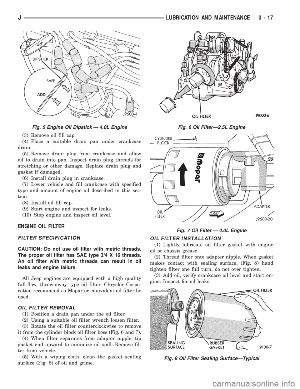
(3) Rotate the oil filter counterclockwise to remove
it from the cylinder block oil filter boss (Fig. 6 and 7).
(4) When filter separates from adapter nipple, tip
gasket end upward to minimize oil spill. Remove fil-
ter from vehicle.
(5) With a wiping cloth, clean the gasket sealing
surface (Fig. 8) of oil and grime.
OIL FILTER INSTALLATION
(1) Lightly lubricate oil filter gasket with engine
oil or chassis grease.
(2) Thread filter onto adapter nipple. When gasket
makes contact with sealing surface, (Fig. 8) hand
tighten filter one full turn, do not over tighten.
(3) Add oil, verify crankcase oil level and start en-
gine. Inspect for oil leaks.
Fig. 5 Engine Oil Dipstick Ð 4.0L EngineFig. 6 Oil FilterÐ2.5L Engine
Fig. 7 Oil Filter Ð 4.0L Engine
Fig. 8 Oil Filter Sealing SurfaceÐTypical
JLUBRICATION AND MAINTENANCE 0 - 17
Page 248 of 2198
WARNING: HOT, PRESSURIZED COOLANT CAN
CAUSE INJURY BY SCALDING.
Carefully remove the radiator pressure cap from
the filler neck and check the coolant level. Push
down on the cap to disengage it from the stop tabs.
Wipe the inner part of the filler neck and examine
the lower inside sealing seat for nicks, cracks, paint,
dirt and solder residue. Inspect the reserve/overflow
tank tube for internal obstructions. Insert a wire
through the tube to be sure it is not obstructed.
Inspect the cams on the outside part of the filler
neck. If the cams are bent, seating of pressure cap
valve and tester seal will be affected. Replace cap if
cams are bent.
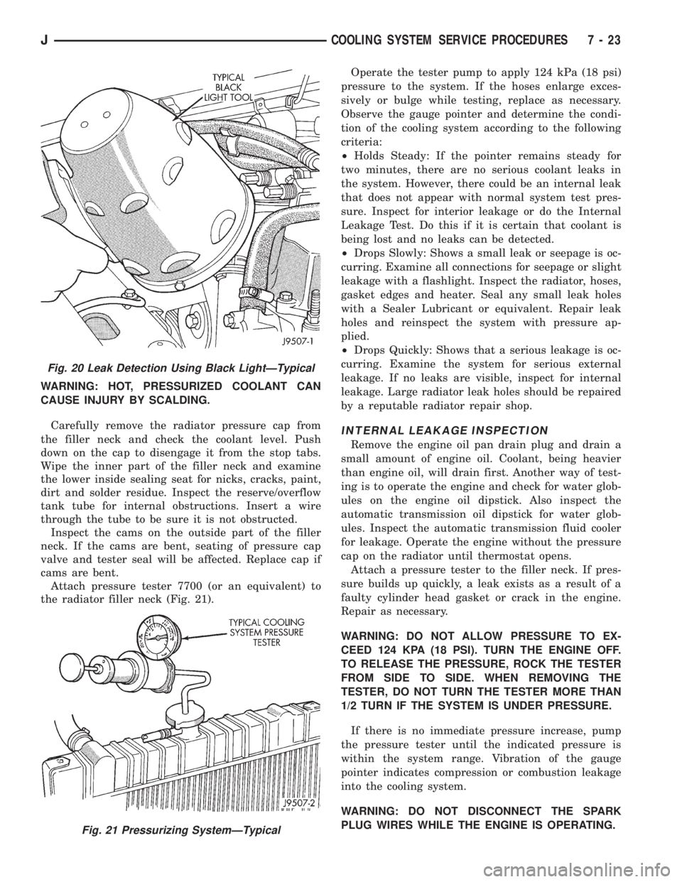
Attach pressure tester 7700 (or an equivalent) to
the radiator filler neck (Fig. 21).Operate the tester pump to apply 124 kPa (18 psi)
pressure to the system. If the hoses enlarge exces-
sively or bulge while testing, replace as necessary.
Observe the gauge pointer and determine the condi-
tion of the cooling system according to the following
criteria:
²Holds Steady: If the pointer remains steady for
two minutes, there are no serious coolant leaks in
the system. However, there could be an internal leak
that does not appear with normal system test pres-
sure. Inspect for interior leakage or do the Internal
Leakage Test. Do this if it is certain that coolant is
being lost and no leaks can be detected.
²Drops Slowly: Shows a small leak or seepage is oc-
curring. Examine all connections for seepage or slight
leakage with a flashlight. Inspect the radiator, hoses,
gasket edges and heater. Seal any small leak holes
with a Sealer Lubricant or equivalent. Repair leak
holes and reinspect the system with pressure ap-
plied.
²Drops Quickly: Shows that a serious leakage is oc-
curring. Examine the system for serious external
leakage. If no leaks are visible, inspect for internal
leakage. Large radiator leak holes should be repaired
by a reputable radiator repair shop.
INTERNAL LEAKAGE INSPECTION
Remove the engine oil pan drain plug and drain a
small amount of engine oil. Coolant, being heavier
than engine oil, will drain first. Another way of test-
ing is to operate the engine and check for water glob-
ules on the engine oil dipstick. Also inspect the
automatic transmission oil dipstick for water glob-
ules. Inspect the automatic transmission fluid cooler
for leakage. Operate the engine without the pressure
cap on the radiator until thermostat opens.
Attach a pressure tester to the filler neck. If pres-
sure builds up quickly, a leak exists as a result of a
faulty cylinder head gasket or crack in the engine.
Repair as necessary.
WARNING: DO NOT ALLOW PRESSURE TO EX-
CEED 124 KPA (18 PSI). TURN THE ENGINE OFF.
TO RELEASE THE PRESSURE, ROCK THE TESTER
FROM SIDE TO SIDE. WHEN REMOVING THE
TESTER, DO NOT TURN THE TESTER MORE THAN
1/2 TURN IF THE SYSTEM IS UNDER PRESSURE.
If there is no immediate pressure increase, pump
the pressure tester until the indicated pressure is
within the system range. Vibration of the gauge
pointer indicates compression or combustion leakage
into the cooling system.
WARNING: DO NOT DISCONNECT THE SPARK
PLUG WIRES WHILE THE ENGINE IS OPERATING.
Fig. 20 Leak Detection Using Black LightÐTypical
Fig. 21 Pressurizing SystemÐTypical
JCOOLING SYSTEM SERVICE PROCEDURES 7 - 23
Page 1122 of 2198
oil on the vibration damper hub contact surface of
the seal.
(9) Apply Mopar Silicone Rubber Adhesive Sealant
to the keyway in the crankshaft and insert the key.
With the key inserted in the keyway in the crank-
shaft, install the vibration damper, washer and bolt.
Lubricate and tighten the bolt to 108 Nzm (80 ft. lbs.)
torque.
(10) Install the serpentine belt and tighten to the
specified tension (refer to Group 7, Cooling Systems
for the proper specifications and procedures).
(11) Install the radiator shroud.
(12) Connect negative cable to battery.
TIMING CASE COVER
REMOVAL
(1) Disconnect negative cable from battery.
(2) Remove the vibration damper (Fig. 4).
(3) Remove the fan and hub assembly and remove
the fan shroud.
(4) Remove the accessory drive brackets that are
attached to the timing case cover.
(5) Remove the A/C compressor (if equipped) and
generator bracket assembly from the engine cylinder
head and move to one side.
(6) Remove the oil pan-to-timing case cover bolts
and timing case cover-to-cylinder block bolts.
(7) Remove the timing case cover and gasket from
the engine.
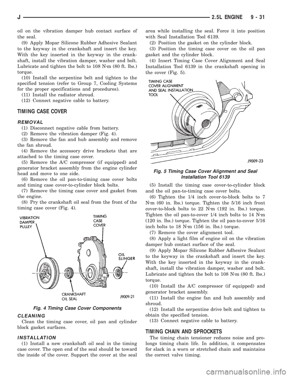
(8) Pry the crankshaft oil seal from the front of the
timing case cover (Fig. 4).
CLEANING
Clean the timing case cover, oil pan and cylinder
block gasket surfaces.
INSTALLATION
(1) Install a new crankshaft oil seal in the timing
case cover. The open end of the seal should be toward
the inside of the cover. Support the cover at the sealarea while installing the seal. Force it into position
with Seal Installation Tool 6139.
(2) Position the gasket on the cylinder block.
(3) Position the timing case cover on the oil pan
gasket and the cylinder block.
(4) Insert Timing Case Cover Alignment and Seal
Installation Tool 6139 in the crankshaft opening in
the cover (Fig. 5).
(5) Install the timing case cover-to-cylinder block
and the oil pan-to-timing case cover bolts.
(6) Tighten the 1/4 inch cover-to-block bolts to 7
Nzm (60 in. lbs.) torque. Tighten the 5/16 inch front
cover-to-block bolts to 22 Nzm (192 in. lbs.) torque.
Tighten the oil pan-to-cover 1/4 inch bolts to 14 Nzm
(120 in. lbs.) torque. Tighten the oil pan-to-cover 5/16
inch bolts to 18 Nzm (156 in. lbs.) torque.
(7) Remove the cover alignment tool.
(8) Apply a light film of engine oil on the vibration
damper hub contact surface of the seal.
(9) Apply Mopar Silicone Rubber Adhesive Sealant
to the keyway in the crankshaft and insert the key.
With the key inserted in the keyway in the crank-
shaft, install the vibration damper, washer and bolt.
Lubricate and tighten the bolt to 108 Nzm (80 ft. lbs.)
torque.
(10) Install the A/C compressor (if equipped) and
generator bracket assembly.
(11) Install the engine fan and hub assembly and
shroud.
(12) Install the serpentine drive belt and tighten to
obtain the specified tension.
(13) Connect negative cable to battery.
TIMING CHAIN AND SPROCKETS
The timing chain tensioner reduces noise and pro-
longs timing chain life. In addition, it compensates
for slack in a worn or stretched chain and maintains
the correct valve timing.
Fig. 4 Timing Case Cover Components
Fig. 5 Timing Case Cover Alignment and Seal
Installation Tool 6139
J2.5L ENGINE 9 - 31
Page 1123 of 2198
REMOVAL
(1) Disconnect negative cable from battery.
(2) Remove the fan and shroud.
(3) Remove the serpentine drive belt.
(4) Remove the crankshaft vibration damper.
(5) Remove the timing case cover.
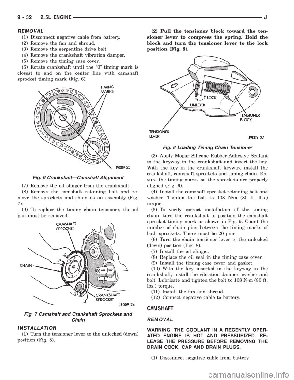
(6) Rotate crankshaft until the ``0'' timing mark is
closest to and on the center line with camshaft
sprocket timing mark (Fig. 6).
(7) Remove the oil slinger from the crankshaft.
(8) Remove the camshaft retaining bolt and re-
move the sprockets and chain as an assembly (Fig.
7).
(9) To replace the timing chain tensioner, the oil
pan must be removed.
INSTALLATION
(1) Turn the tensioner lever to the unlocked (down)
position (Fig. 8).(2) Pull the tensioner block toward the ten-
sioner lever to compress the spring. Hold the
block and turn the tensioner lever to the lock
position (Fig. 8).
(3) Apply Mopar Silicone Rubber Adhesive Sealant
to the keyway in the crankshaft and insert the key.
With the key in the crankshaft keyway, install the
crankshaft, camshaft sprockets and timing chain. En-
sure the timing marks on the sprockets are properly
aligned (Fig. 6).
(4) Install the camshaft sprocket retaining bolt and
washer. Tighten the bolt to 108 Nzm (80 ft. lbs.)
torque.
(5) To verify correct installation of the timing
chain, turn the crankshaft to position the camshaft
sprocket timing mark as shown in Fig. 9. Count the
number of chain pins between the timing marks of
both sprockets. There must be 20 pins.
(6) Turn the chain tensioner lever to the unlocked
(down) position (Fig. 8).
(7) Install the oil slinger.
(8) Replace the oil seal in the timing case cover.
(9) Install the timing case cover and gasket.
(10) With the key inserted in the keyway in the
crankshaft, install the vibration damper, washer and
bolt. Lubricate and tighten the bolt to 108 Nzm (80 ft.
lbs.) torque.
(11) Install the fan and shroud.
(12) Connect negative cable to battery.
CAMSHAFT
REMOVAL
WARNING: THE COOLANT IN A RECENTLY OPER-
ATED ENGINE IS HOT AND PRESSURIZED. RE-
LEASE THE PRESSURE BEFORE REMOVING THE
DRAIN COCK, CAP AND DRAIN PLUGS.
(1) Disconnect negative cable from battery.
Fig. 6 CrankshaftÐCamshaft Alignment
Fig. 7 Camshaft and Crankshaft Sprockets and
Chain
Fig. 8 Loading Timing Chain Tensioner
9 - 32 2.5L ENGINEJ
Page 1125 of 2198
tor in the Component Removal/Installation section of
Group 8D, Ignition Systems.
(14) Install the distributor and ignition wires. Re-
fer to Distributor in the Component Removal/Instal-
lation section of Group 8D, Ignition Systems.
(15) Install the radiator or radiator and condenser,
if equipped with A/C.
(16) Fill the cooling system.
(17) Connect negative cable to battery.
CAMSHAFT PIN REPLACEMENT
REMOVAL
WARNING: DO NOT LOOSEN THE RADIATOR
DRAIN COCK WITH THE SYSTEM HOT AND PRES-
SURIZED BECAUSE SERIOUS BURNS FROM COOL-
ANT CAN OCCUR.
(1) Disconnect negative cable from battery.
(2) Drain the radiator. DO NOT waste reusable
coolant. Drain the coolant into a clean container.
(3) Remove the fan and shroud.
(4) Disconnect the radiator overflow tube, radiator
hoses, automatic transmission fluid cooler pipes (if
equipped).
(5) Remove the radiator.
(6) If equipped with air conditioning:
CAUTION: DO NOT loosen or disconnect any air
conditioner system fittings. Move the condenser
and receiver/drier aside as a complete assembly.
(a) Remove the A/C compressor serpentine drive
belt idler pulley.
(b) Disconnect and remove the generator.
(c) Remove the A/C condenser attaching bolts
and move the condenser and receiver/drier assem-
bly up and out of the way.
(7) Remove the serpentine drive belt.
(8) Remove the crankshaft vibration damper.
(9) Remove the timing case cover. Clean the gasket
material from the cover.
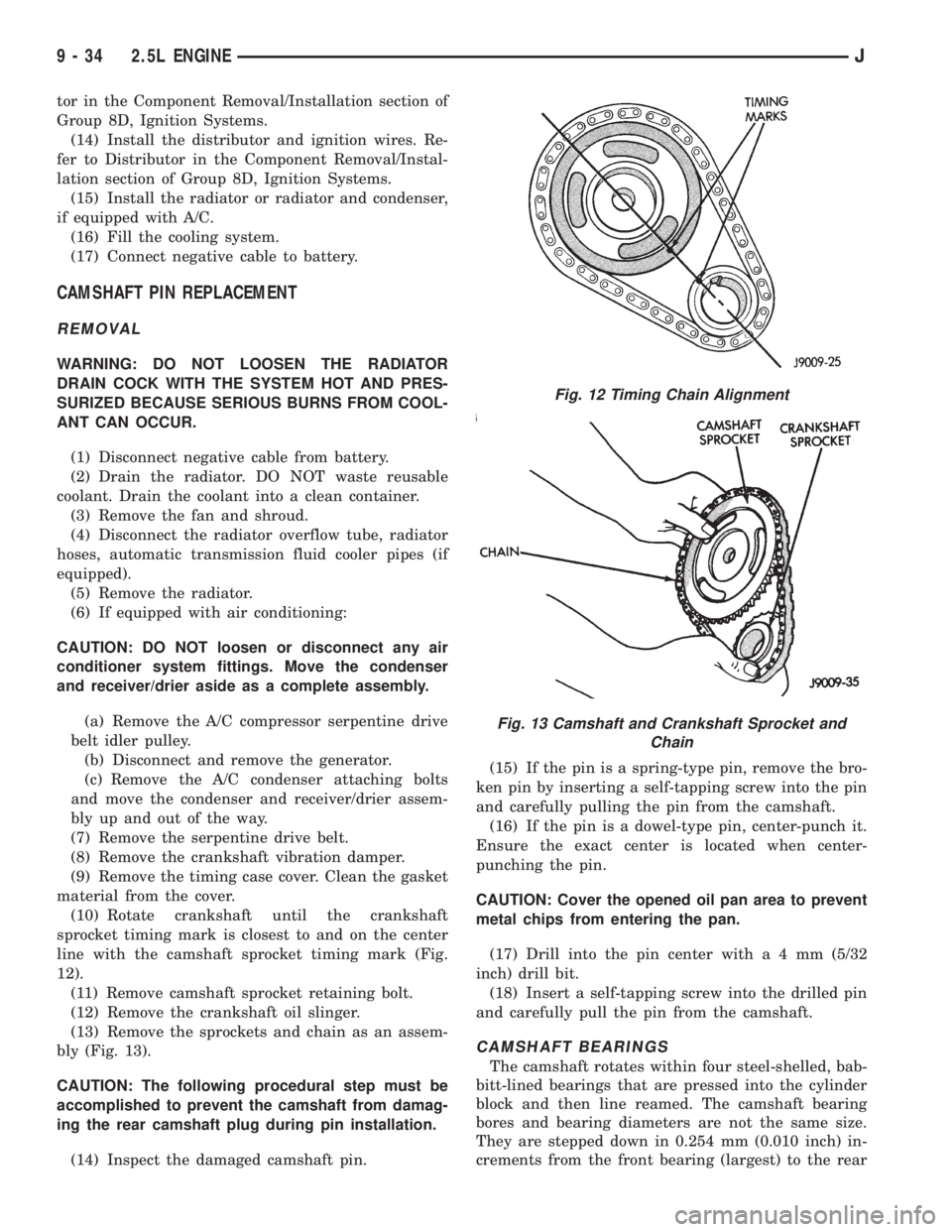
(10) Rotate crankshaft until the crankshaft
sprocket timing mark is closest to and on the center
line with the camshaft sprocket timing mark (Fig.
12).
(11) Remove camshaft sprocket retaining bolt.
(12) Remove the crankshaft oil slinger.
(13) Remove the sprockets and chain as an assem-
bly (Fig. 13).
CAUTION: The following procedural step must be
accomplished to prevent the camshaft from damag-
ing the rear camshaft plug during pin installation.
(14) Inspect the damaged camshaft pin.(15) If the pin is a spring-type pin, remove the bro-
ken pin by inserting a self-tapping screw into the pin
and carefully pulling the pin from the camshaft.
(16) If the pin is a dowel-type pin, center-punch it.
Ensure the exact center is located when center-
punching the pin.
CAUTION: Cover the opened oil pan area to prevent
metal chips from entering the pan.
(17) Drill into the pin center witha4mm(5/32
inch) drill bit.
(18) Insert a self-tapping screw into the drilled pin
and carefully pull the pin from the camshaft.
CAMSHAFT BEARINGS
The camshaft rotates within four steel-shelled, bab-
bitt-lined bearings that are pressed into the cylinder
block and then line reamed. The camshaft bearing
bores and bearing diameters are not the same size.
They are stepped down in 0.254 mm (0.010 inch) in-
crements from the front bearing (largest) to the rear
Fig. 12 Timing Chain Alignment
Fig. 13 Camshaft and Crankshaft Sprocket and
Chain
9 - 34 2.5L ENGINEJ
Page 1126 of 2198
bearing (smallest). This permits easier removal and
installation of the camshaft. The camshaft bearings
are pressure lubricated.
It is not advisable to attempt to replace cam-
shaft bearings unless special removal and in-
stallation tools are available.
Camshaft end play is maintained by the load
placed on the camshaft by the oil pump and distrib-
utor drive gear. The helical cut of the gear holds the
camshaft sprocket thrust face against the cylinder
block face.
INSTALLATION
(1) Clean the camshaft pin hole.
(2) Compress the center of the replacement spring
pin with vise grips.
(3) Carefully drive the pin into the camshaft pin
hole until it is seated.
(4) Install the camshaft sprocket, crankshaft
sprocket and timing chain with the timing marks
aligned (Fig. 12).
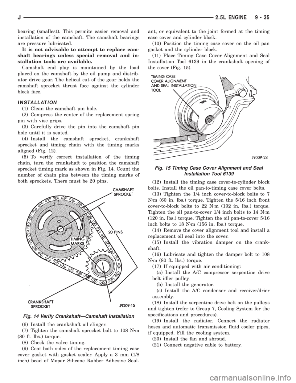
(5) To verify correct installation of the timing
chain, turn the crankshaft to position the camshaft
sprocket timing mark as shown in Fig. 14. Count the
number of chain pins between the timing marks of
both sprockets. There must be 20 pins.
(6) Install the crankshaft oil slinger.
(7) Tighten the camshaft sprocket bolt to 108 Nzm
(80 ft. lbs.) torque.
(8) Check the valve timing.
(9) Coat both sides of the replacement timing case
cover gasket with gasket sealer. Applya3mm(1/8
inch) bead of Mopar Silicone Rubber Adhesive Seal-ant, or equivalent to the joint formed at the timing
case cover and cylinder block.
(10) Position the timing case cover on the oil pan
gasket and the cylinder block.
(11) Place Timing Case Cover Alignment and Seal
Installation Tool 6139 in the crankshaft opening of
the cover (Fig. 15).
(12) Install the timing case cover-to-cylinder block
bolts. Install the oil pan-to-timing case cover bolts.
(13) Tighten the 1/4 inch cover-to-block bolts to 7
Nzm (60 in. lbs.) torque. Tighten the 5/16 inch front
cover-to-block bolts to 22 Nzm (192 in. lbs.) torque.
Tighten the oil pan-to-cover 1/4 inch bolts to 14 Nzm
(120 in. lbs.) torque. Tighten the oil pan-to-cover 5/16
inch bolts to 18 Nzm (156 in. lbs.) torque.
(14) Remove the cover alignment tool and install a
replacement oil seal into the cover.
(15) Install the vibration damper on the crank-
shaft.
(16) Lubricate and tighten the damper bolt to 108
Nzm (80 ft. lbs.) torque.
(17) If equipped with air conditioning:
(a) Install the A/C compressor serpentine drive
belt idler pulley.
(b) Install the generator.
(c) Install the A/C condenser and receiver/drier
assembly.
(18) Install the serpentine drive belt on the pulleys
and tighten (refer to Group 7, Cooling System for the
specifications and procedures).
(19) Install the radiator. Connect the radiator
hoses and automatic transmission fluid cooler pipes,
if equipped. Fill the cooling system.
(20) Install the fan and shroud.
(21) Connect negative cable to battery.
Fig. 14 Verify CrankshaftÐCamshaft Installation
Fig. 15 Timing Case Cover Alignment and Seal
Installation Tool 6139
J2.5L ENGINE 9 - 35
Page 1127 of 2198
OIL PAN
REMOVAL
(1) Disconnect negative cable from battery.
(2) Raise the vehicle.
(3) Remove the oil pan drain plug and drain the
engine oil.
(4) Disconnect the exhaust pipe at the engine ex-
haust manifold.
(5) Disconnect the exhaust hanger at the catalytic
converter and lower the pipe.
(6) Remove the engine starter motor.
(7) Remove the flywheel/torque converter housing
access cover.
(8) Position a jack stand directly under the engine
vibration damper.
(9) Place a piece of wood (2 x 2) between the jack
stand and the engine vibration damper.
(10) Remove the engine mount through bolts.
(11) Using the jack stand, raise the engine until
adequate clearance is obtained to remove the oil pan.
(12) Remove the oil pan bolts. Carefully remove
the oil pan and gasket.
CLEANING
Clean the block and pan gasket surfaces.
INSTALLATION
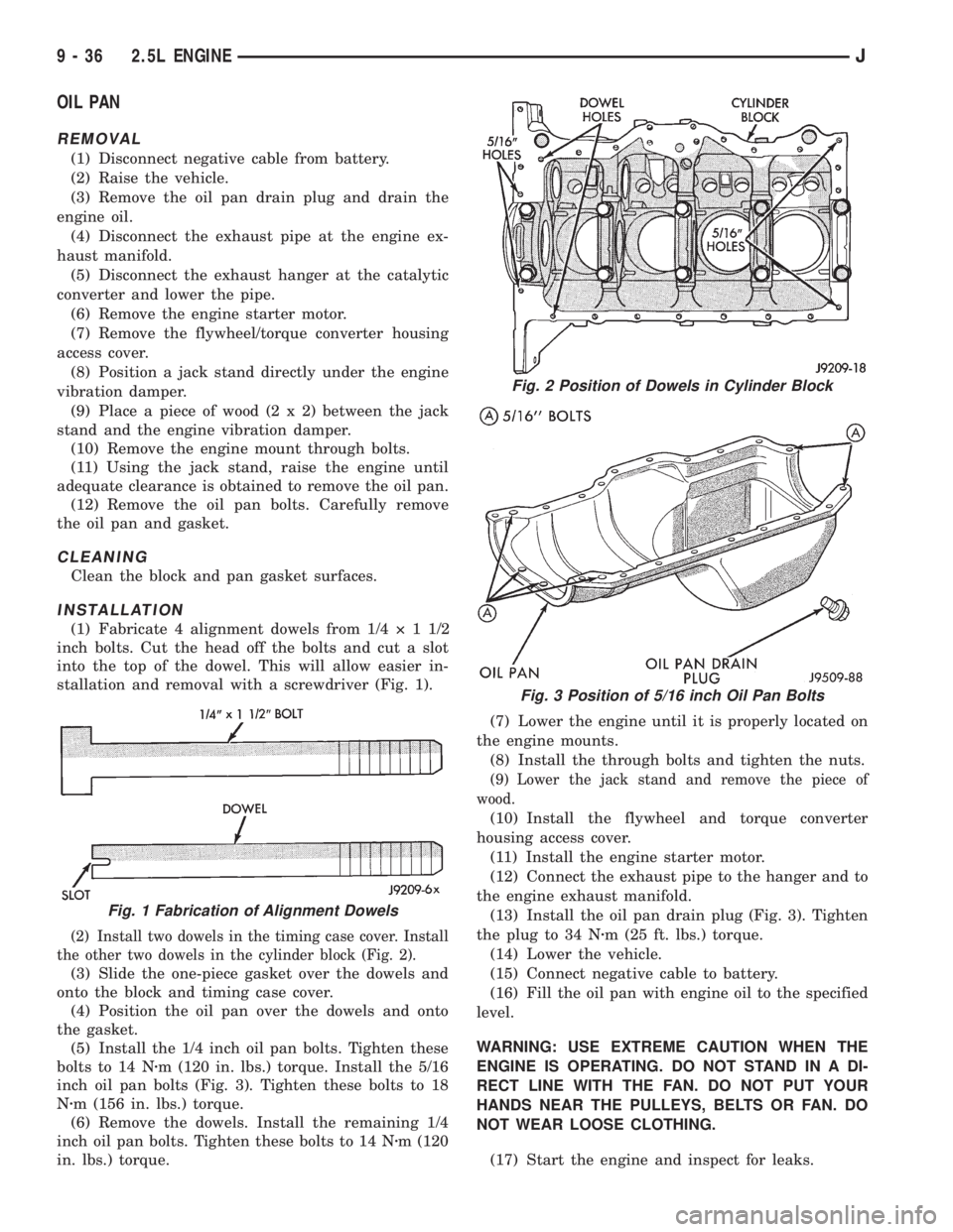
(1) Fabricate 4 alignment dowels from 1/4ý11/2
inch bolts. Cut the head off the bolts and cut a slot
into the top of the dowel. This will allow easier in-
stallation and removal with a screwdriver (Fig. 1).
(2) Install two dowels in the timing case cover. Install
the other two dowels in the cylinder block (Fig. 2).
(3) Slide the one-piece gasket over the dowels and
onto the block and timing case cover.
(4) Position the oil pan over the dowels and onto
the gasket.
(5) Install the 1/4 inch oil pan bolts. Tighten these
bolts to 14 Nzm (120 in. lbs.) torque. Install the 5/16
inch oil pan bolts (Fig. 3). Tighten these bolts to 18
Nzm (156 in. lbs.) torque.
(6) Remove the dowels. Install the remaining 1/4
inch oil pan bolts. Tighten these bolts to 14 Nzm (120
in. lbs.) torque.(7) Lower the engine until it is properly located on
the engine mounts.
(8) Install the through bolts and tighten the nuts.
(9) Lower the jack stand and remove the piece of
wood.
(10) Install the flywheel and torque converter
housing access cover.
(11) Install the engine starter motor.
(12) Connect the exhaust pipe to the hanger and to
the engine exhaust manifold.
(13) Install the oil pan drain plug (Fig. 3). Tighten
the plug to 34 Nzm (25 ft. lbs.) torque.
(14) Lower the vehicle.
(15) Connect negative cable to battery.
(16) Fill the oil pan with engine oil to the specified
level.
WARNING: USE EXTREME CAUTION WHEN THE
ENGINE IS OPERATING. DO NOT STAND IN A DI-
RECT LINE WITH THE FAN. DO NOT PUT YOUR
HANDS NEAR THE PULLEYS, BELTS OR FAN. DO
NOT WEAR LOOSE CLOTHING.
(17) Start the engine and inspect for leaks.
Fig. 1 Fabrication of Alignment Dowels
Fig. 2 Position of Dowels in Cylinder Block
Fig. 3 Position of 5/16 inch Oil Pan Bolts
9 - 36 2.5L ENGINEJ
Page 1130 of 2198
OIL PUMP
The positive-displacement gear-type oil pump is
driven by the distributor shaft, which is driven by a
gear on the camshaft. Oil is siphoned into the pump
through an inlet tube and strainer assembly that is
pressed into the pump body.
The pump incorporates a nonadjustable pressure
relief valve to limit maximum pressure to 517 kPa
(75 psi). In the relief position, the valve permits oil to
bypass through a passage in the pump body to the
inlet side of the pump.
Oil pump removal or replacement will not affect
the distributor timing because the distributor drive
gear remains in mesh with the camshaft gear.
REMOVAL
(1) Drain the engine oil.
(2) Remove the oil pan.
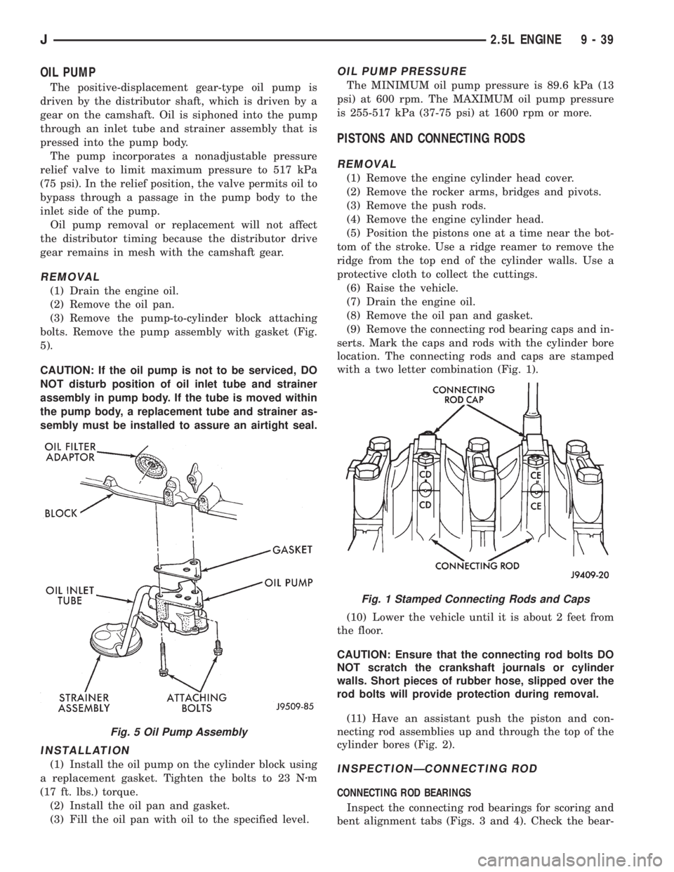
(3) Remove the pump-to-cylinder block attaching
bolts. Remove the pump assembly with gasket (Fig.
5).
CAUTION: If the oil pump is not to be serviced, DO
NOT disturb position of oil inlet tube and strainer
assembly in pump body. If the tube is moved within
the pump body, a replacement tube and strainer as-
sembly must be installed to assure an airtight seal.
INSTALLATION
(1) Install the oil pump on the cylinder block using
a replacement gasket. Tighten the bolts to 23 Nzm
(17 ft. lbs.) torque.
(2) Install the oil pan and gasket.
(3) Fill the oil pan with oil to the specified level.
OIL PUMP PRESSURE
The MINIMUM oil pump pressure is 89.6 kPa (13
psi) at 600 rpm. The MAXIMUM oil pump pressure
is 255-517 kPa (37-75 psi) at 1600 rpm or more.
PISTONS AND CONNECTING RODS
REMOVAL
(1) Remove the engine cylinder head cover.
(2) Remove the rocker arms, bridges and pivots.
(3) Remove the push rods.
(4) Remove the engine cylinder head.
(5) Position the pistons one at a time near the bot-
tom of the stroke. Use a ridge reamer to remove the
ridge from the top end of the cylinder walls. Use a
protective cloth to collect the cuttings.
(6) Raise the vehicle.
(7) Drain the engine oil.
(8) Remove the oil pan and gasket.
(9) Remove the connecting rod bearing caps and in-
serts. Mark the caps and rods with the cylinder bore
location. The connecting rods and caps are stamped
with a two letter combination (Fig. 1).
(10) Lower the vehicle until it is about 2 feet from
the floor.
CAUTION: Ensure that the connecting rod bolts DO
NOT scratch the crankshaft journals or cylinder
walls. Short pieces of rubber hose, slipped over the
rod bolts will provide protection during removal.
(11) Have an assistant push the piston and con-
necting rod assemblies up and through the top of the
cylinder bores (Fig. 2).
INSPECTIONÐCONNECTING ROD
CONNECTING ROD BEARINGS
Inspect the connecting rod bearings for scoring and
bent alignment tabs (Figs. 3 and 4). Check the bear-
Fig. 5 Oil Pump Assembly
Fig. 1 Stamped Connecting Rods and Caps
J2.5L ENGINE 9 - 39