1995 JEEP CHEROKEE head gasket
[x] Cancel search: head gasketPage 244 of 2198
INSTALLATION
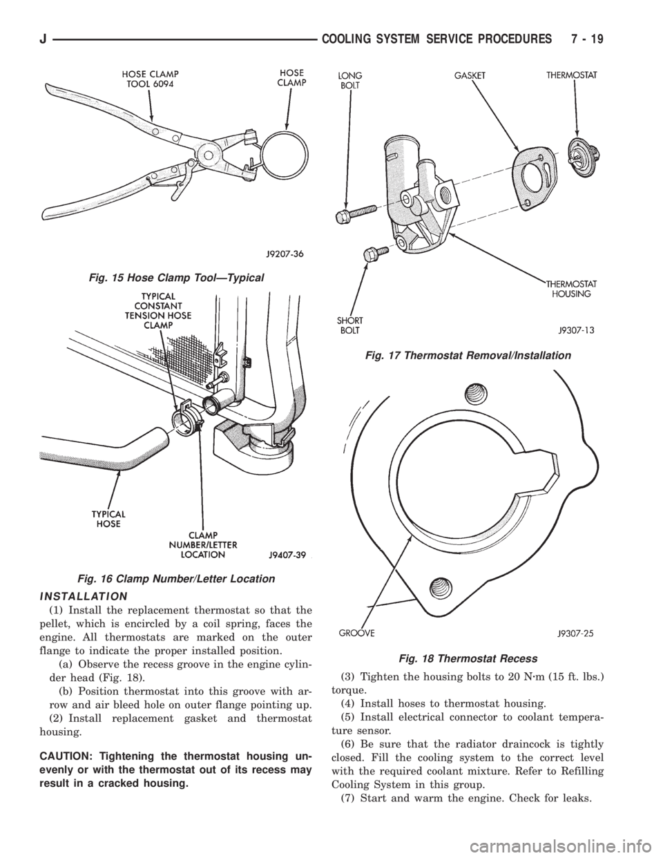
(1) Install the replacement thermostat so that the
pellet, which is encircled by a coil spring, faces the
engine. All thermostats are marked on the outer
flange to indicate the proper installed position.
(a) Observe the recess groove in the engine cylin-
der head (Fig. 18).
(b) Position thermostat into this groove with ar-
row and air bleed hole on outer flange pointing up.
(2) Install replacement gasket and thermostat
housing.
CAUTION: Tightening the thermostat housing un-
evenly or with the thermostat out of its recess may
result in a cracked housing.(3) Tighten the housing bolts to 20 Nzm (15 ft. lbs.)
torque.
(4) Install hoses to thermostat housing.
(5) Install electrical connector to coolant tempera-
ture sensor.
(6) Be sure that the radiator draincock is tightly
closed. Fill the cooling system to the correct level
with the required coolant mixture. Refer to Refilling
Cooling System in this group.
(7) Start and warm the engine. Check for leaks.
Fig. 15 Hose Clamp ToolÐTypical
Fig. 16 Clamp Number/Letter Location
Fig. 17 Thermostat Removal/Installation
Fig. 18 Thermostat Recess
JCOOLING SYSTEM SERVICE PROCEDURES 7 - 19
Page 248 of 2198
WARNING: HOT, PRESSURIZED COOLANT CAN
CAUSE INJURY BY SCALDING.
Carefully remove the radiator pressure cap from
the filler neck and check the coolant level. Push
down on the cap to disengage it from the stop tabs.
Wipe the inner part of the filler neck and examine
the lower inside sealing seat for nicks, cracks, paint,
dirt and solder residue. Inspect the reserve/overflow
tank tube for internal obstructions. Insert a wire
through the tube to be sure it is not obstructed.
Inspect the cams on the outside part of the filler
neck. If the cams are bent, seating of pressure cap
valve and tester seal will be affected. Replace cap if
cams are bent.
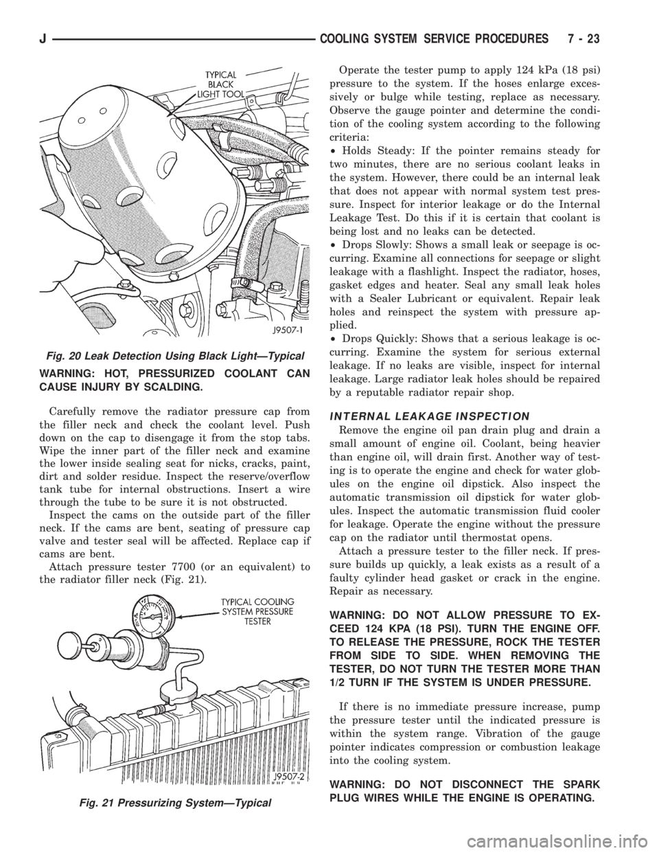
Attach pressure tester 7700 (or an equivalent) to
the radiator filler neck (Fig. 21).Operate the tester pump to apply 124 kPa (18 psi)
pressure to the system. If the hoses enlarge exces-
sively or bulge while testing, replace as necessary.
Observe the gauge pointer and determine the condi-
tion of the cooling system according to the following
criteria:
²Holds Steady: If the pointer remains steady for
two minutes, there are no serious coolant leaks in
the system. However, there could be an internal leak
that does not appear with normal system test pres-
sure. Inspect for interior leakage or do the Internal
Leakage Test. Do this if it is certain that coolant is
being lost and no leaks can be detected.
²Drops Slowly: Shows a small leak or seepage is oc-
curring. Examine all connections for seepage or slight
leakage with a flashlight. Inspect the radiator, hoses,
gasket edges and heater. Seal any small leak holes
with a Sealer Lubricant or equivalent. Repair leak
holes and reinspect the system with pressure ap-
plied.
²Drops Quickly: Shows that a serious leakage is oc-
curring. Examine the system for serious external
leakage. If no leaks are visible, inspect for internal
leakage. Large radiator leak holes should be repaired
by a reputable radiator repair shop.
INTERNAL LEAKAGE INSPECTION
Remove the engine oil pan drain plug and drain a
small amount of engine oil. Coolant, being heavier
than engine oil, will drain first. Another way of test-
ing is to operate the engine and check for water glob-
ules on the engine oil dipstick. Also inspect the
automatic transmission oil dipstick for water glob-
ules. Inspect the automatic transmission fluid cooler
for leakage. Operate the engine without the pressure
cap on the radiator until thermostat opens.
Attach a pressure tester to the filler neck. If pres-
sure builds up quickly, a leak exists as a result of a
faulty cylinder head gasket or crack in the engine.
Repair as necessary.
WARNING: DO NOT ALLOW PRESSURE TO EX-
CEED 124 KPA (18 PSI). TURN THE ENGINE OFF.
TO RELEASE THE PRESSURE, ROCK THE TESTER
FROM SIDE TO SIDE. WHEN REMOVING THE
TESTER, DO NOT TURN THE TESTER MORE THAN
1/2 TURN IF THE SYSTEM IS UNDER PRESSURE.
If there is no immediate pressure increase, pump
the pressure tester until the indicated pressure is
within the system range. Vibration of the gauge
pointer indicates compression or combustion leakage
into the cooling system.
WARNING: DO NOT DISCONNECT THE SPARK
PLUG WIRES WHILE THE ENGINE IS OPERATING.
Fig. 20 Leak Detection Using Black LightÐTypical
Fig. 21 Pressurizing SystemÐTypical
JCOOLING SYSTEM SERVICE PROCEDURES 7 - 23
Page 473 of 2198
HEADLAMP SWITCHÐYJ
To remove or replace the headlamp switch, refer to
Group 8E, Instrument Panel and Gauges.
FOG LAMP SWITCH REPLACEMENTÐYJ
REMOVAL
The fog lamp switch is located on the instrument
panel at the right of the steering column. The fog
lamp circuit relay is located below the left headlamp.
(1) Disconnect the battery negative cable.
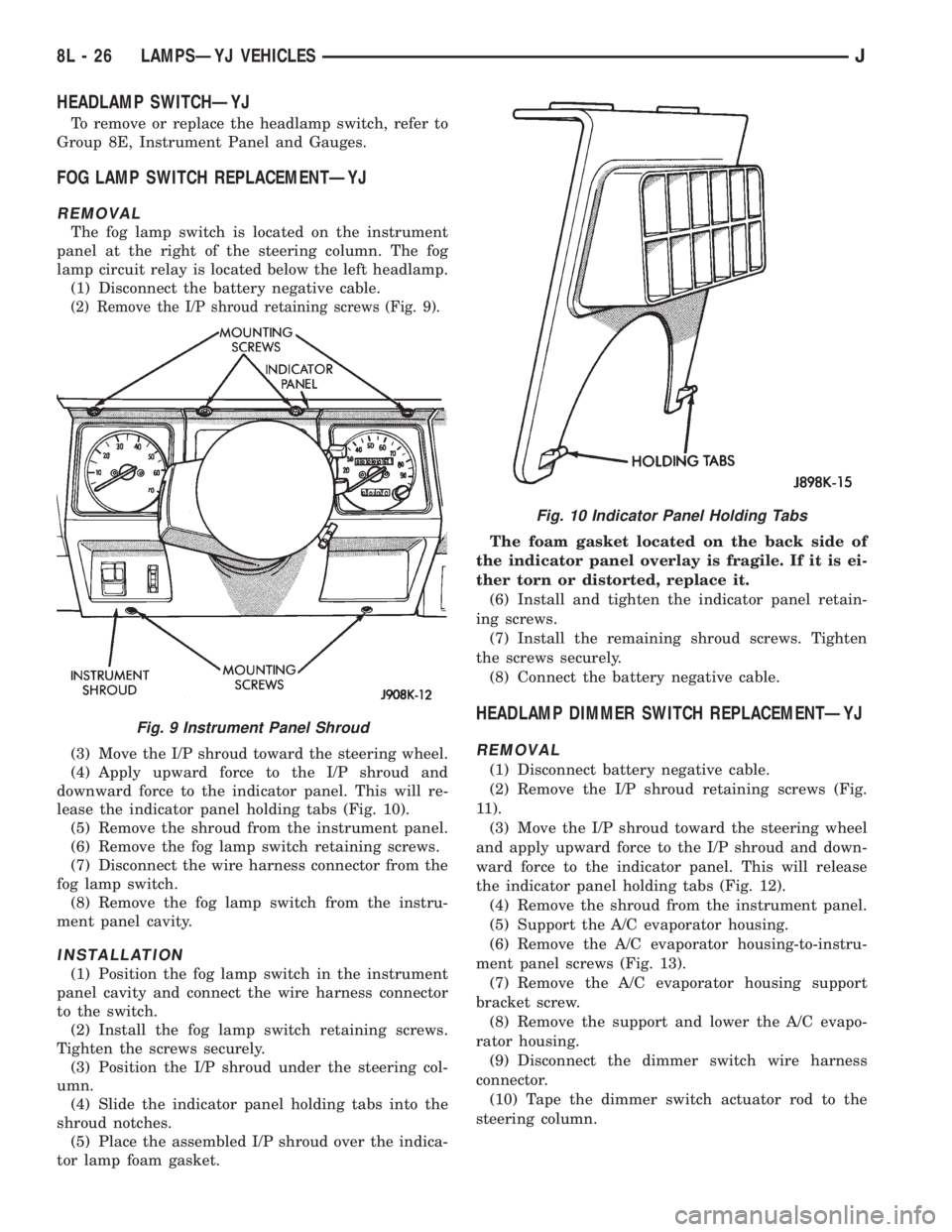
(2) Remove the I/P shroud retaining screws (Fig. 9).
(3) Move the I/P shroud toward the steering wheel.
(4) Apply upward force to the I/P shroud and
downward force to the indicator panel. This will re-
lease the indicator panel holding tabs (Fig. 10).
(5) Remove the shroud from the instrument panel.
(6) Remove the fog lamp switch retaining screws.
(7) Disconnect the wire harness connector from the
fog lamp switch.
(8) Remove the fog lamp switch from the instru-
ment panel cavity.
INSTALLATION
(1) Position the fog lamp switch in the instrument
panel cavity and connect the wire harness connector
to the switch.
(2) Install the fog lamp switch retaining screws.
Tighten the screws securely.
(3) Position the I/P shroud under the steering col-
umn.
(4) Slide the indicator panel holding tabs into the
shroud notches.
(5) Place the assembled I/P shroud over the indica-
tor lamp foam gasket.The foam gasket located on the back side of
the indicator panel overlay is fragile. If it is ei-
ther torn or distorted, replace it.
(6) Install and tighten the indicator panel retain-
ing screws.
(7) Install the remaining shroud screws. Tighten
the screws securely.
(8) Connect the battery negative cable.
HEADLAMP DIMMER SWITCH REPLACEMENTÐYJ
REMOVAL
(1) Disconnect battery negative cable.
(2) Remove the I/P shroud retaining screws (Fig.
11).
(3) Move the I/P shroud toward the steering wheel
and apply upward force to the I/P shroud and down-
ward force to the indicator panel. This will release
the indicator panel holding tabs (Fig. 12).
(4) Remove the shroud from the instrument panel.
(5) Support the A/C evaporator housing.
(6) Remove the A/C evaporator housing-to-instru-
ment panel screws (Fig. 13).
(7) Remove the A/C evaporator housing support
bracket screw.
(8) Remove the support and lower the A/C evapo-
rator housing.
(9) Disconnect the dimmer switch wire harness
connector.
(10) Tape the dimmer switch actuator rod to the
steering column.
Fig. 9 Instrument Panel Shroud
Fig. 10 Indicator Panel Holding Tabs
8L - 26 LAMPSÐYJ VEHICLESJ
Page 474 of 2198
(11) Remove the dimmer switch screws and detach
the switch from the rod.
INSTALLATION
(1) Force the dimmer switch onto the actuator rod
and install screws.DO NOT tighten the retaining
screws at this time.
(2) Remove the tape attaching the actuator rod to
the steering column.
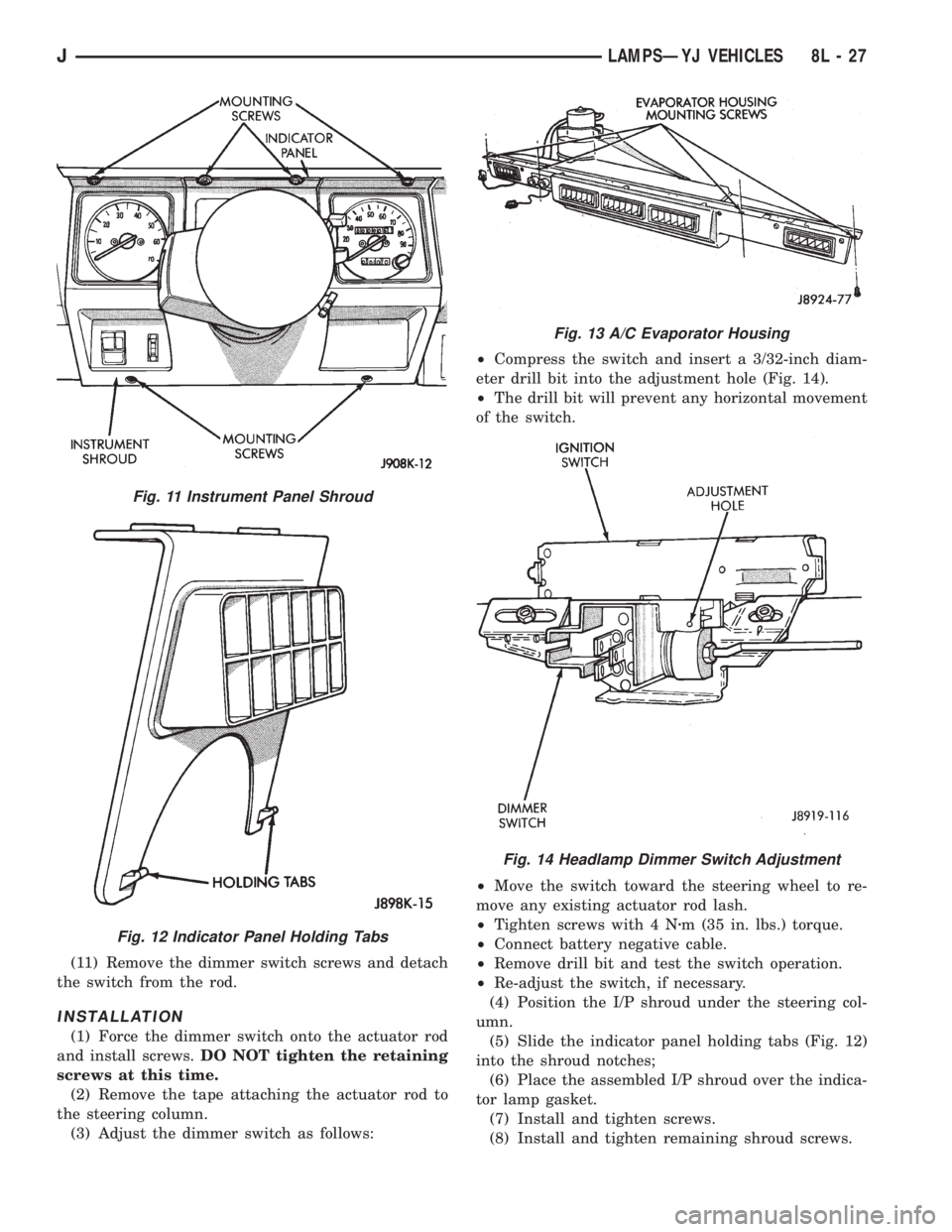
(3) Adjust the dimmer switch as follows:²Compress the switch and insert a 3/32-inch diam-
eter drill bit into the adjustment hole (Fig. 14).
²The drill bit will prevent any horizontal movement
of the switch.
²Move the switch toward the steering wheel to re-
move any existing actuator rod lash.
²Tighten screws with 4 Nzm (35 in. lbs.) torque.
²Connect battery negative cable.
²Remove drill bit and test the switch operation.
²Re-adjust the switch, if necessary.
(4) Position the I/P shroud under the steering col-
umn.
(5) Slide the indicator panel holding tabs (Fig. 12)
into the shroud notches;
(6) Place the assembled I/P shroud over the indica-
tor lamp gasket.
(7) Install and tighten screws.
(8) Install and tighten remaining shroud screws.
Fig. 11 Instrument Panel Shroud
Fig. 12 Indicator Panel Holding Tabs
Fig. 13 A/C Evaporator Housing
Fig. 14 Headlamp Dimmer Switch Adjustment
JLAMPSÐYJ VEHICLES 8L - 27
Page 1096 of 2198
ENGINE DIAGNOSIS
Engine diagnosis is helpful in determining the
causes of malfunctions not detected and remedied by
routine tune-ups.
These malfunctions may be classified as either per-
formance (e.g., engine idles rough and stalls) or me-
chanical (e.g., a strange noise).
Refer to the Service DiagnosisÐPerformance chart
and the Service DiagnosisÐMechanical chart for pos-
sible causes and corrections of malfunctions. Refer to
Group 14, Fuel System for the fuel system diagnosis.
GENERAL INFORMATION
Additional tests and diagnostic procedures may be
necessary for specific engine malfunctions that can
not be isolated with the Service Diagnosis charts. In-
formation concerning additional tests and diagnosis
is provided within the following diagnosis:
²Cylinder Compression Pressure Test.
²Cylinder Combustion Pressure Leakage Test.
²Engine Cylinder Head Gasket Failure Diagnosis.
²Intake Manifold Leakage Diagnosis.
INTAKE MANIFOLD LEAKAGE DIAGNOSIS
An intake manifold air leak is characterized by
lower than normal manifold vacuum. Also, one or
more cylinders may not be functioning.
WARNING: USE EXTREME CAUTION WHEN THE
ENGINE IS OPERATING. DO NOT STAND IN A DI-
RECT LINE WITH THE FAN. DO NOT PUT YOUR
HANDS NEAR THE PULLEYS, BELTS OR THE FAN.
DO NOT WEAR LOOSE CLOTHING.
METHOD 1
(1) Start the engine.
(2) Spray a small stream of water at the suspected
leak area.
(3) If a change in RPM'S, the area of the suspected
leak has been found.
(4) Repair as required.
CYLINDER COMPRESSION PRESSURE TEST
The results of a cylinder compression pressure test
can be utilized to diagnose several engine malfunc-
tions.
Ensure the battery is completely charged and the
engine starter motor is in good operating condition.
Otherwise the indicated compression pressures may
not be valid for diagnosis purposes.
(1) Clean the spark plug recesses with compressed
air.
(2) Remove the spark plugs.
(3) Secure the throttle in the wide-open position.
(4) Disconnect the ignition coil.(5) Insert a compression pressure gauge and rotate
the engine with the engine starter motor for three
revolutions.
(6) Record the compression pressure on the 3rd
revolution. Continue the test for the remaining cylin-
ders.
Refer to Engine Specifications for the correct en-
gine compression pressures.
ENGINE CYLINDER HEAD GASKET FAILURE
DIAGNOSIS
A leaking engine cylinder head gasket usually re-
sults in loss of power, loss of coolant and engine mis-
firing.
An engine cylinder head gasket leak can be located
between adjacent cylinders or between a cylinder and
the adjacent water jacket.
²An engine cylinder head gasket leaking between
adjacent cylinders is indicated by a loss of power
and/or engine misfire.
²An engine cylinder head gasket leaking between a
cylinder and an adjacent water jacket is indicated by
coolant foaming or overheating and loss of coolant.
CYLINDER-TO-CYLINDER LEAKAGE TEST
To determine if an engine cylinder head gasket is
leaking between adjacent cylinders; follow the proce-
dures outlined in Cylinder Compression Pressure
Test. An engine cylinder head gasket leaking between
adjacent cylinders will result in approximately a 50-
70% reduction in compression pressure.
CYLINDER-TO-WATER JACKET LEAKAGE
TEST
WARNING: USE EXTREME CAUTION WHEN THE
ENGINE IS OPERATING. DO NOT STAND IN A DI-
RECT LINE WITH THE FAN. DO NOT PUT YOUR
HANDS NEAR THE PULLEYS, BELTS OR THE FAN.
DO NOT WEAR LOOSE CLOTHING.
Remove the radiator cap.
Start the engine and allow it to warm up until the
engine thermostat opens.
If a large combustion/compression pressure leak ex-
ists, bubbles will be visible in the coolant.
If bubbles are not visible, install a radiator pres-
sure tester and pressurize the coolant system.
If a cylinder is leaking combustion pressure into
the water jacket, the tester pointer will pulsate with
every combustion stroke of the cylinder.
JENGINES 9 - 5
Page 1113 of 2198
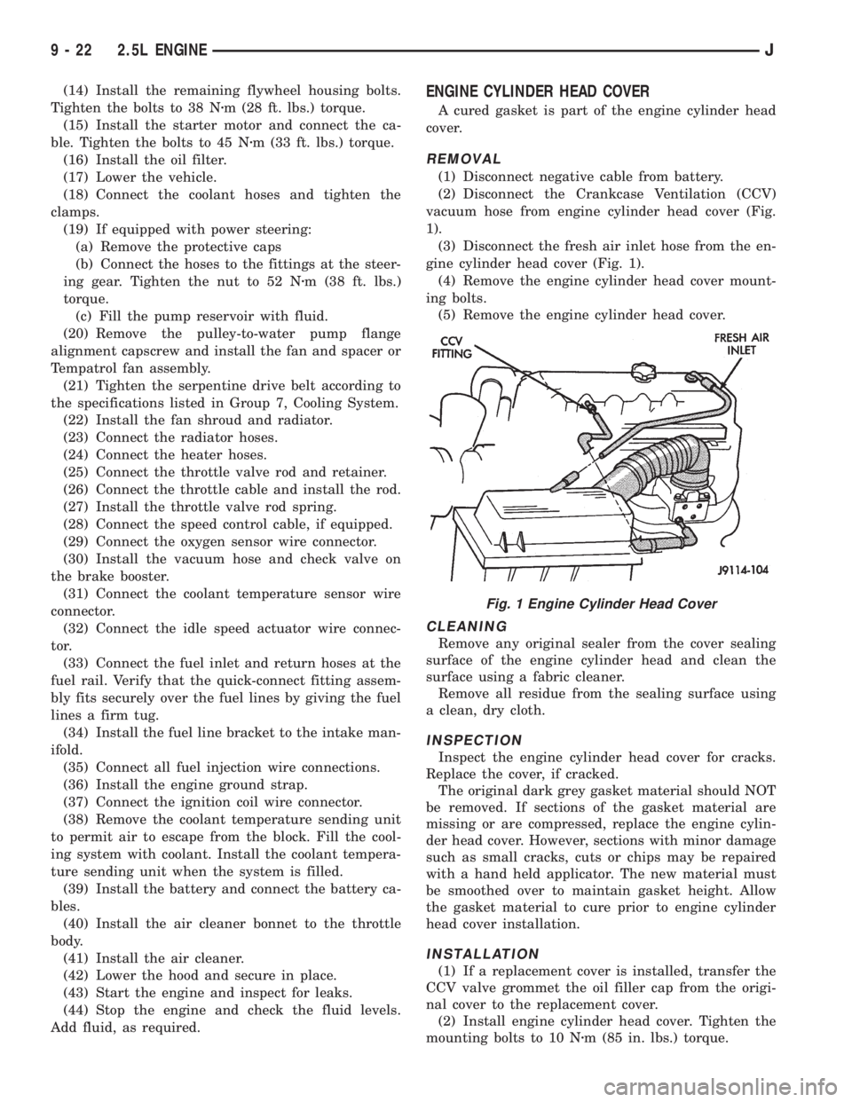
(14) Install the remaining flywheel housing bolts.
Tighten the bolts to 38 Nzm (28 ft. lbs.) torque.
(15) Install the starter motor and connect the ca-
ble. Tighten the bolts to 45 Nzm (33 ft. lbs.) torque.
(16) Install the oil filter.
(17) Lower the vehicle.
(18) Connect the coolant hoses and tighten the
clamps.
(19) If equipped with power steering:
(a) Remove the protective caps
(b) Connect the hoses to the fittings at the steer-
ing gear. Tighten the nut to 52 Nzm (38 ft. lbs.)
torque.
(c) Fill the pump reservoir with fluid.
(20) Remove the pulley-to-water pump flange
alignment capscrew and install the fan and spacer or
Tempatrol fan assembly.
(21) Tighten the serpentine drive belt according to
the specifications listed in Group 7, Cooling System.
(22) Install the fan shroud and radiator.
(23) Connect the radiator hoses.
(24) Connect the heater hoses.
(25) Connect the throttle valve rod and retainer.
(26) Connect the throttle cable and install the rod.
(27) Install the throttle valve rod spring.
(28) Connect the speed control cable, if equipped.
(29) Connect the oxygen sensor wire connector.
(30) Install the vacuum hose and check valve on
the brake booster.
(31) Connect the coolant temperature sensor wire
connector.
(32) Connect the idle speed actuator wire connec-
tor.
(33) Connect the fuel inlet and return hoses at the
fuel rail. Verify that the quick-connect fitting assem-
bly fits securely over the fuel lines by giving the fuel
lines a firm tug.
(34) Install the fuel line bracket to the intake man-
ifold.
(35) Connect all fuel injection wire connections.
(36) Install the engine ground strap.
(37) Connect the ignition coil wire connector.
(38) Remove the coolant temperature sending unit
to permit air to escape from the block. Fill the cool-
ing system with coolant. Install the coolant tempera-
ture sending unit when the system is filled.
(39) Install the battery and connect the battery ca-
bles.
(40) Install the air cleaner bonnet to the throttle
body.
(41) Install the air cleaner.
(42) Lower the hood and secure in place.
(43) Start the engine and inspect for leaks.
(44) Stop the engine and check the fluid levels.
Add fluid, as required.ENGINE CYLINDER HEAD COVER
A cured gasket is part of the engine cylinder head
cover.
REMOVAL
(1) Disconnect negative cable from battery.
(2) Disconnect the Crankcase Ventilation (CCV)
vacuum hose from engine cylinder head cover (Fig.
1).
(3) Disconnect the fresh air inlet hose from the en-
gine cylinder head cover (Fig. 1).
(4) Remove the engine cylinder head cover mount-
ing bolts.
(5) Remove the engine cylinder head cover.
CLEANING
Remove any original sealer from the cover sealing
surface of the engine cylinder head and clean the
surface using a fabric cleaner.
Remove all residue from the sealing surface using
a clean, dry cloth.
INSPECTION
Inspect the engine cylinder head cover for cracks.
Replace the cover, if cracked.
The original dark grey gasket material should NOT
be removed. If sections of the gasket material are
missing or are compressed, replace the engine cylin-
der head cover. However, sections with minor damage
such as small cracks, cuts or chips may be repaired
with a hand held applicator. The new material must
be smoothed over to maintain gasket height. Allow
the gasket material to cure prior to engine cylinder
head cover installation.
INSTALLATION
(1) If a replacement cover is installed, transfer the
CCV valve grommet the oil filler cap from the origi-
nal cover to the replacement cover.
(2) Install engine cylinder head cover. Tighten the
mounting bolts to 10 Nzm (85 in. lbs.) torque.
Fig. 1 Engine Cylinder Head Cover
9 - 22 2.5L ENGINEJ
Page 1117 of 2198
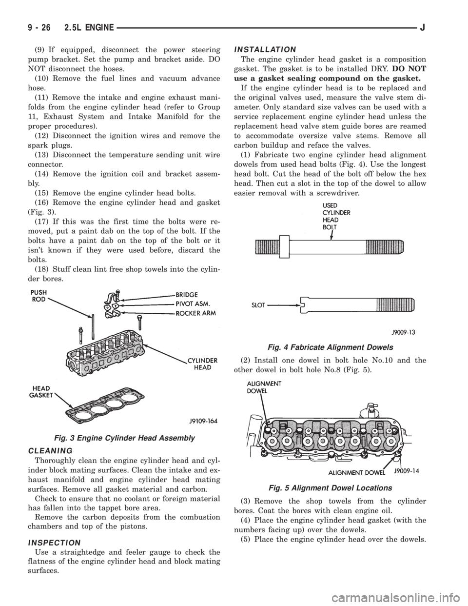
(9) If equipped, disconnect the power steering
pump bracket. Set the pump and bracket aside. DO
NOT disconnect the hoses.
(10) Remove the fuel lines and vacuum advance
hose.
(11) Remove the intake and engine exhaust mani-
folds from the engine cylinder head (refer to Group
11, Exhaust System and Intake Manifold for the
proper procedures).
(12) Disconnect the ignition wires and remove the
spark plugs.
(13) Disconnect the temperature sending unit wire
connector.
(14) Remove the ignition coil and bracket assem-
bly.
(15) Remove the engine cylinder head bolts.
(16) Remove the engine cylinder head and gasket
(Fig. 3).
(17) If this was the first time the bolts were re-
moved, put a paint dab on the top of the bolt. If the
bolts have a paint dab on the top of the bolt or it
isn't known if they were used before, discard the
bolts.
(18) Stuff clean lint free shop towels into the cylin-
der bores.
CLEANING
Thoroughly clean the engine cylinder head and cyl-
inder block mating surfaces. Clean the intake and ex-
haust manifold and engine cylinder head mating
surfaces. Remove all gasket material and carbon.
Check to ensure that no coolant or foreign material
has fallen into the tappet bore area.
Remove the carbon deposits from the combustion
chambers and top of the pistons.
INSPECTION
Use a straightedge and feeler gauge to check the
flatness of the engine cylinder head and block mating
surfaces.
INSTALLATION
The engine cylinder head gasket is a composition
gasket. The gasket is to be installed DRY.DO NOT
use a gasket sealing compound on the gasket.
If the engine cylinder head is to be replaced and
the original valves used, measure the valve stem di-
ameter. Only standard size valves can be used with a
service replacement engine cylinder head unless the
replacement head valve stem guide bores are reamed
to accommodate oversize valve stems. Remove all
carbon buildup and reface the valves.
(1) Fabricate two engine cylinder head alignment
dowels from used head bolts (Fig. 4). Use the longest
head bolt. Cut the head of the bolt off below the hex
head. Then cut a slot in the top of the dowel to allow
easier removal with a screwdriver.
(2) Install one dowel in bolt hole No.10 and the
other dowel in bolt hole No.8 (Fig. 5).
(3) Remove the shop towels from the cylinder
bores. Coat the bores with clean engine oil.
(4) Place the engine cylinder head gasket (with the
numbers facing up) over the dowels.
(5) Place the engine cylinder head over the dowels.
Fig. 3 Engine Cylinder Head Assembly
Fig. 4 Fabricate Alignment Dowels
Fig. 5 Alignment Dowel Locations
9 - 26 2.5L ENGINEJ
Page 1119 of 2198
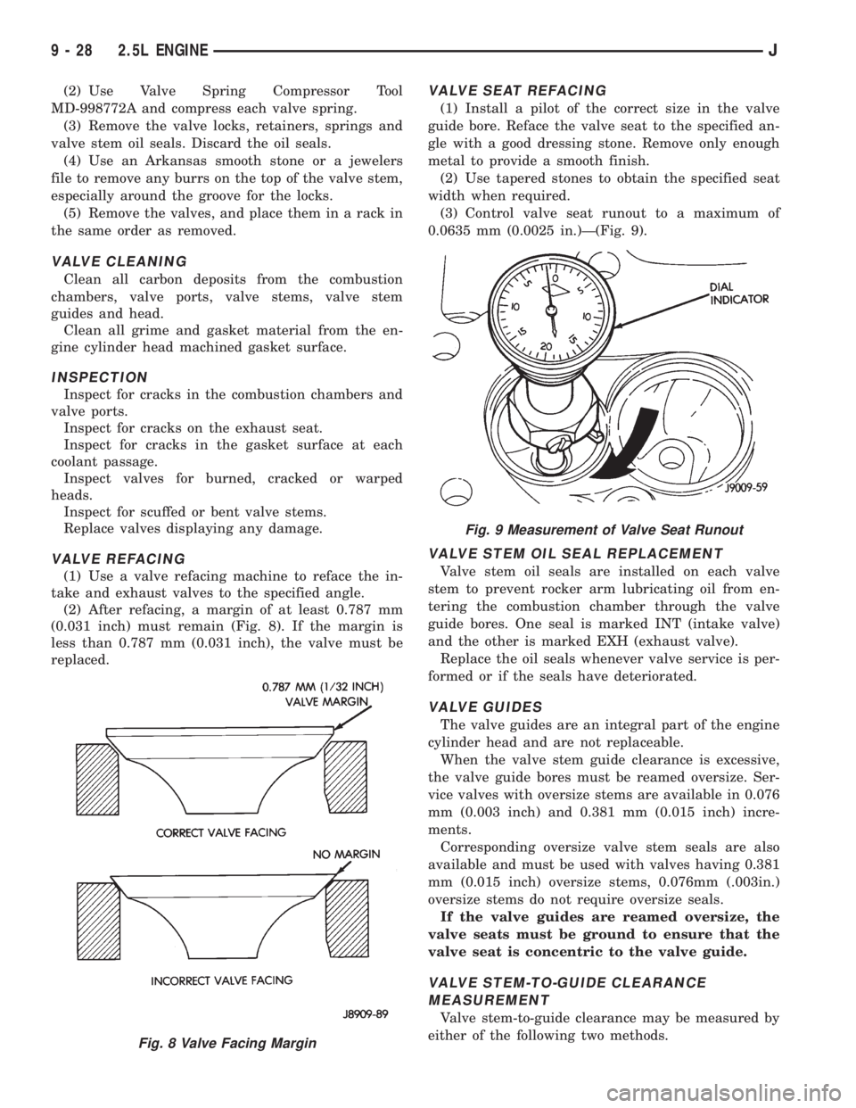
(2) Use Valve Spring Compressor Tool
MD-998772A and compress each valve spring.
(3) Remove the valve locks, retainers, springs and
valve stem oil seals. Discard the oil seals.
(4) Use an Arkansas smooth stone or a jewelers
file to remove any burrs on the top of the valve stem,
especially around the groove for the locks.
(5) Remove the valves, and place them in a rack in
the same order as removed.
VALVE CLEANING
Clean all carbon deposits from the combustion
chambers, valve ports, valve stems, valve stem
guides and head.
Clean all grime and gasket material from the en-
gine cylinder head machined gasket surface.
INSPECTION
Inspect for cracks in the combustion chambers and
valve ports.
Inspect for cracks on the exhaust seat.
Inspect for cracks in the gasket surface at each
coolant passage.
Inspect valves for burned, cracked or warped
heads.
Inspect for scuffed or bent valve stems.
Replace valves displaying any damage.
VALVE REFACING
(1) Use a valve refacing machine to reface the in-
take and exhaust valves to the specified angle.
(2) After refacing, a margin of at least 0.787 mm
(0.031 inch) must remain (Fig. 8). If the margin is
less than 0.787 mm (0.031 inch), the valve must be
replaced.
VALVE SEAT REFACING
(1) Install a pilot of the correct size in the valve
guide bore. Reface the valve seat to the specified an-
gle with a good dressing stone. Remove only enough
metal to provide a smooth finish.
(2) Use tapered stones to obtain the specified seat
width when required.
(3) Control valve seat runout to a maximum of
0.0635 mm (0.0025 in.)Ð(Fig. 9).
VALVE STEM OIL SEAL REPLACEMENT
Valve stem oil seals are installed on each valve
stem to prevent rocker arm lubricating oil from en-
tering the combustion chamber through the valve
guide bores. One seal is marked INT (intake valve)
and the other is marked EXH (exhaust valve).
Replace the oil seals whenever valve service is per-
formed or if the seals have deteriorated.
VALVE GUIDES
The valve guides are an integral part of the engine
cylinder head and are not replaceable.
When the valve stem guide clearance is excessive,
the valve guide bores must be reamed oversize. Ser-
vice valves with oversize stems are available in 0.076
mm (0.003 inch) and 0.381 mm (0.015 inch) incre-
ments.
Corresponding oversize valve stem seals are also
available and must be used with valves having 0.381
mm (0.015 inch) oversize stems, 0.076mm (.003in.)
oversize stems do not require oversize seals.
If the valve guides are reamed oversize, the
valve seats must be ground to ensure that the
valve seat is concentric to the valve guide.
VALVE STEM-TO-GUIDE CLEARANCE
MEASUREMENT
Valve stem-to-guide clearance may be measured by
either of the following two methods.
Fig. 8 Valve Facing Margin
Fig. 9 Measurement of Valve Seat Runout
9 - 28 2.5L ENGINEJ