1995 JEEP CHEROKEE seat
[x] Cancel search: seatPage 1704 of 2198
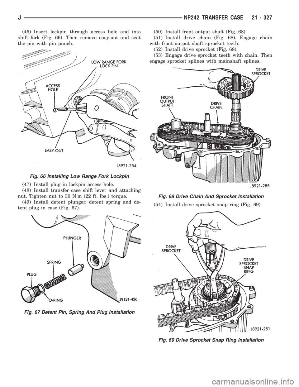
(46) Insert lockpin through access hole and into
shift fork (Fig. 66). Then remove easy-out and seat
the pin with pin punch.
(47) Install plug in lockpin access hole.
(48) Install transfer case shift lever and attaching
nut. Tighten nut to 30 Nzm (22 ft. lbs.) torque.
(49) Install detent plunger, detent spring and de-
tent plug in case (Fig. 67).(50) Install front output shaft (Fig. 68).
(51) Install drive chain (Fig. 68). Engage chain
with front output shaft sprocket teeth.
(52) Install drive sprocket (Fig. 68).
(53) Engage drive sprocket teeth with chain. Then
engage sprocket splines with mainshaft splines.
(54) Install drive sprocket snap ring (Fig. 69).
Fig. 66 Installing Low Range Fork Lockpin
Fig. 67 Detent Pin, Spring And Plug Installation
Fig. 68 Drive Chain And Sprocket Installation
Fig. 69 Drive Sprocket Snap Ring Installation
JNP242 TRANSFER CASE 21 - 327
Page 1705 of 2198
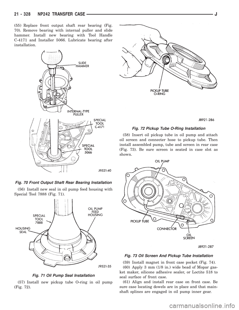
(55) Replace front output shaft rear bearing (Fig.
70). Remove bearing with internal puller and slide
hammer. Install new bearing with Tool Handle
C-4171 and Installer 5066. Lubricate bearing after
installation.
(56) Install new seal in oil pump feed housing with
Special Tool 7888 (Fig. 71).
(57) Install new pickup tube O-ring in oil pump
(Fig. 72).(58) Insert oil pickup tube in oil pump and attach
oil screen and connecter hose to pickup tube. Then
install assembled pump, tube and screen in rear case
(Fig. 73). Be sure screen is seated in case slot as
shown.
(59) Install magnet in front case pocket (Fig. 74).
(60) Apply 3 mm (1/8 in.) wide bead of Mopar gas-
ket maker, silicone adhesive sealer, or Loctite 518 to
seal surface of front case.
(61) Align and install rear case on front case. Be
sure case locating dowels are in place and that main-
shaft splines are engaged in oil pump inner gear.
Fig. 70 Front Output Shaft Rear Bearing Installation
Fig. 71 Oil Pump Seal Installation
Fig. 72 Pickup Tube O-Ring Installation
Fig. 73 Oil Screen And Pickup Tube Installation
21 - 328 NP242 TRANSFER CASEJ
Page 1706 of 2198
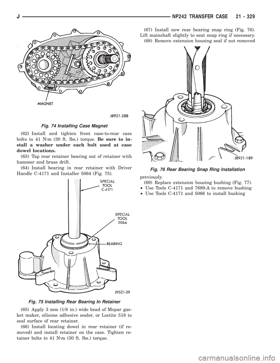
(62) Install and tighten front case-to-rear case
bolts to 41 Nzm (30 ft. lbs.) torque.Be sure to in-
stall a washer under each bolt used at case
dowel locations.
(63) Tap rear retainer bearing out of retainer with
hammer and brass drift.
(64) Install bearing in rear retainer with Driver
Handle C-4171 and Installer 5064 (Fig. 75).
(65) Apply 3 mm (1/8 in.) wide bead of Mopar gas-
ket maker, silicone adhesive sealer, or Loctite 518 to
seal surface of rear retainer.
(66) Install locating dowel in rear retainer (if re-
moved) and install retainer on the case. Tighten re-
tainer bolts to 41 Nzm (30 ft. lbs.) torque.(67) Install new rear bearing snap ring (Fig. 76).
Lift mainshaft slightly to seat snap ring if necessary.
(68) Remove extension housing seal if not removed
previously.
(69) Replace extension housing bushing (Fig. 77).
²Use Tools C-4171 and 7889-A to remove bushing
²Use Tools C-4171 and 5066 to install bushing
Fig. 74 Installing Case Magnet
Fig. 75 Installing Rear Bearing In Retainer
Fig. 76 Rear Bearing Snap Ring Installation
JNP242 TRANSFER CASE 21 - 329
Page 1707 of 2198
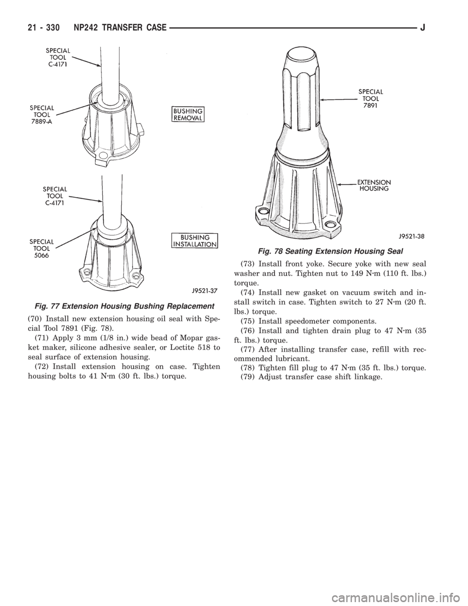
(70) Install new extension housing oil seal with Spe-
cial Tool 7891 (Fig. 78).
(71) Apply 3 mm (1/8 in.) wide bead of Mopar gas-
ket maker, silicone adhesive sealer, or Loctite 518 to
seal surface of extension housing.
(72) Install extension housing on case. Tighten
housing bolts to 41 Nzm (30 ft. lbs.) torque.(73) Install front yoke. Secure yoke with new seal
washer and nut. Tighten nut to 149 Nzm (110 ft. lbs.)
torque.
(74) Install new gasket on vacuum switch and in-
stall switch in case. Tighten switch to 27 Nzm (20 ft.
lbs.) torque.
(75) Install speedometer components.
(76) Install and tighten drain plug to 47 Nzm (35
ft. lbs.) torque.
(77) After installing transfer case, refill with rec-
ommended lubricant.
(78) Tighten fill plug to 47 Nzm (35 ft. lbs.) torque.
(79) Adjust transfer case shift linkage.
Fig. 77 Extension Housing Bushing Replacement
Fig. 78 Seating Extension Housing Seal
21 - 330 NP242 TRANSFER CASEJ
Page 1731 of 2198
VEHICLE VIBRATION
Vehicle vibration can be caused by:
²Tire/wheel unbalance or excessive runout
²Defective tires with extreme tread wear
²Nylon overlay flat spots (performance tires only)
²Incorrect wheel bearing adjustment (if applicable)
²Loose or worn suspension/steering components
²Certain tire tread patterns
²Incorrect drive shaft angles or excessive drive
shaft/yoke runout
²Defective or worn U-joints
²Excessive brake rotor or drum runout
²Loose engine or transmission supports/mounts
²And by engine operated accessories
Refer to the appropriate Groups in this man-
ual for additional information.
VIBRATION TYPES
There are two types of vehicle vibration:
²Mechanical
²Audible.
Mechanical vehicle vibration can be felt through
the seats, floor pan and/or steering wheel.
Audible vehicle vibration is heard above normal
background noise. The sound can be a droning or
drumming noise.
Vibrations are sensitive to change in engine torque,
vehicle speed or engine speed.
ENGINE TORQUE SENSITIVE VIBRATION
This vibration can be increased or decreased by:
²Accelerating
²Decelerating
²Coasting
²Maintaining a constant vehicle speed
VEHICLE SPEED SENSITIVE VIBRATION
This vibration condition always occurs at the same
vehicle speed regardless of the engine torque or en-
gine speed.
ENGINE SPEED (RPM) SENSITIVE VIBRATION
This vibration occurs at varying engine speeds. It
can be isolated by increasing or decreasing the en-
gine speed with the transmission in NEUTRAL posi-
tion.
VIBRATION DIAGNOSIS
A vibration diagnosis should always begin with a
10 mile (16 km) trip (to warm the vehicle and tires).
Then a road test to identify the vibration. Corrective
action should not be attempted until the vibration
type has been identified via a road test.
During the road test, drive the vehicle on a smooth
surface. If vibration exists, note and record the fol-
lowing information:²Identify the vehicle speed range when the vibra-
tion occurs
²Identify the type of vibration
²Identify the vibration sensitivity
²Determine if the vibration is affected by changes
in vehicle speed, engine speed and engine torque.
When the vibration has been identified, refer to the
Vibration Diagnosis chart for causes. Consider cor-
recting only those causes coded in the chart that are
related to the vibration condition.
Refer to the following cause codes and descriptions
for explanations when referring to the chart.
TRRÐTire and Wheel Radial Runout:Vehicle
speed sensitive, mechanical vibration. The runout
will not cause vibration below 20 mph (32 km/h).
WHÐWheel Hop:Vehicle speed sensitive, me-
chanical vibration. The wheel hop generates rapid
up-down movement in the steering wheel. The vibra-
tion is most noticeable in the 20 - 40 mph (32 - 64
km/h) range. The wheel hop will not cause vibration
below 20 mph (32 km/h). Wheel hop is caused by a
tire/wheel that has a radial runout of more than
0.045 of-an-inch (1.14 mm). If wheel runout is accept-
able and combined runout cannot be reduced by re-
positioning the tire on wheel, replace tire.
TBÐTire/Wheel Balance:Vehicle speed sensitive,
mechanical vibration. Static tire/wheel unbalance
will not cause vibration below 30 mph (46 km/h). Dy-
namic tire/wheel unbalance will not cause vibration
below 40 mph (64 km/h).
TLRÐTire/Wheel Lateral runout:Vehicle speed
sensitive, mechanical vibration. The runout will not
cause vibration below 50 - 55 mph (80 - 88 km/h). Ex-
cessive lateral runout will also cause front-end
shimmy.
TWÐTire Wear:Vehicle speed sensitive, audible
vibration. Abnormal tire wear causes small vibration
in the 30 - 55 mph (88 km/h) range. This will pro-
duce a whine noise at high speed. The whine will
change to a growl noise when the speed is reduced.
WÐTire Waddle:Vehicle speed sensitive, mechan-
ical vibration. Irregular tire uniformity can cause
side-to-side motion during speeds up to 15 mph (24
km/h). If the motion is excessive, identify the defec-
tive tire and replace it.
UAJÐUniversal Joint (Drive Shaft) Angles:
Torque/vehicle speed sensitive, mechanical/audible vi-
bration. Incorrect drive shaft angles cause mechani-
cal vibration below 20 mph (32 km/h) and in the 70
mph (112 km/h) range. The incorrect angles can also
produce an audible vibration in the 20 - 50 mph (32 -
80 km/h) range. Caster adjustment could be required
to correct the angles.
UJÐUniversal Joints:Engine torque/vehicle
speed sensitive, mechanical/audible vibration. If the
22 - 10 WHEELS AND TIRESJ
Page 1744 of 2198
(2) Install the hinge nuts on the studs. Tighten the
restraint cable nut to 4 Nzm (38 in-lbs) torque.
Tighten the remaining nuts to 9 Nzm (77 in-lbs)
torque.
If a replacement hinge seal is being installed,
position it around the hinge arm, force it
against the hinge base.
(3) Position the hinge seal around the hinge arm
and on hinge base.
(4) Install the hood.
(5) Adjust the hood as necessary.
HOOD LATCH REPLACEMENTÐXJ
REMOVAL
(1) Remove the screw that attaches the latch to the
hood inner panel (Fig. 15).
(2) Disconnect the latch from the hood and latch
connecting rod. Remove the latch from the hood.
INSTALLATION
(1) Connect the latch to the latch connecting rod
and position it on the hood inner panel.
(2) Install the screw that attaches the latch to the
hood inner panel.
(3) Tighten the screw to 9 Nzm (77 in-lbs) torque.
(4) Test the operation of the latch release cable and
latch.
HOOD LATCH STRIKER REPLACEMENTÐXJ
REMOVE
(1) Remove the grille opening panel (GOP).
(2) Remove the screws that attach the striker to
the radiator baffle (Fig. 19).
(3) Remove the striker and shims from the baffle.
INSTALLATION
(1) Position the shims and striker on the radiator
baffle and install the screws.
(2) Tighten the screws to 21 Nzm (15 ft-lbs) torque.
(3) Test the striker/hood alignment by opening and
closing the hood several times. Adjust the striker, if
necessary.
LATCH RELEASE CABLE REPLACEMENTÐXJ
REMOVAL
(1) Drill out the bellcrank to hood rivet heads and
remove the rivets (Fig. 14).
(2) Disconnect the bellcrank from the latch rod and
the latch release cable. Remove the bellcrank from
the hood.
(3) Disconnect the latch release cable from the
clips on the hood.
(4) Remove the left cowl side trim panel.
(5) Remove the cable bracket screws from the cowl
side panel.(6) Pull the cable through the dash panel and re-
move it from under the instrument panel.
INSTALLATION
(1) Insert the replacement cable end through the
hole in the dash panel into the engine compartment.
(2) Pull the cable forward and seat the grommet in
the dash panel.
(3) Position the cable bracket on the cowl side
panel and install the screws. Tighten the screws to
13 Nzm (111 in-lbs) torque.
(4) Install the left cowl side trim panel.
(5) Connect the cable and latch rod to the
bellcrank.
(6) Position the bellcrank on the hood and install
the rivets.
(7) Attach the cable to the clips.
(8) Test release the cable for proper operation.
SAFETY LATCH STRIKER REPLACEMENTÐXJ
REMOVAL
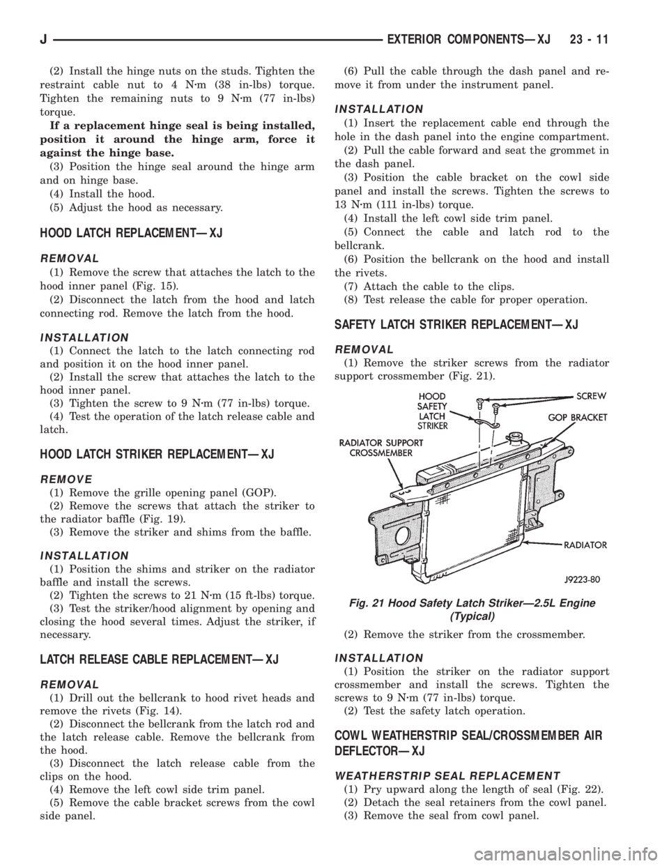
(1) Remove the striker screws from the radiator
support crossmember (Fig. 21).
(2) Remove the striker from the crossmember.
INSTALLATION
(1) Position the striker on the radiator support
crossmember and install the screws. Tighten the
screws to 9 Nzm (77 in-lbs) torque.
(2) Test the safety latch operation.
COWL WEATHERSTRIP SEAL/CROSSMEMBER AIR
DEFLECTORÐXJ
WEATHERSTRIP SEAL REPLACEMENT
(1) Pry upward along the length of seal (Fig. 22).
(2) Detach the seal retainers from the cowl panel.
(3) Remove the seal from cowl panel.
Fig. 21 Hood Safety Latch StrikerÐ2.5L Engine
(Typical)
JEXTERIOR COMPONENTSÐXJ 23 - 11
Page 1759 of 2198
(3) Pull downward and remove the grille from ex-
haust port in the door opening panel.
INSTALLATION
(1) Position the slot located in the upper end of re-
placement grille at the exhaust port and insert edge
in the slot.
(2) Push inward and seat the grille in the exhaust
port.
(3) Install the screw to attach the grille to the door
opening panel.
EXTERIOR NAMEPLATESÐXJ
SERVICE INFORMATION
All of nameplates, with the exception of the JEEP
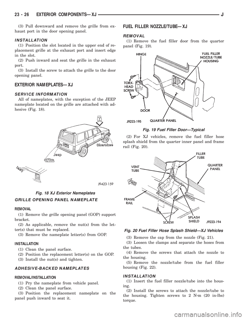
nameplate located on the grille are attached with ad-
hesive (Fig. 18).
GRILLE OPENING PANEL NAMEPLATE
REMOVAL
(1) Remove the grille opening panel (GOP) support
bracket.
(2) As applicable, remove the nut(s) from the let-
ter(s) that must be replaced.
(3) Remove the nameplate letter(s) from GOP.
INSTALLATION
(1) Clean the panel surface.
(2) Position the replacement letter(s) on the GOP.
(3) Install the nut(s) and tighten.
ADHESIVE-BACKED NAMEPLATES
REMOVAL/INSTALLATION
(1) Pry the nameplate from vehicle panel.
(2) Clean the panel surface.
(3) Position the replacement nameplate on the
panel push inward to seat it.
FUEL FILLER NOZZLE/TUBEÐXJ
REMOVAL
(1) Remove the fuel filler door from the quarter
panel (Fig. 19).
(2) For XJ vehicles, remove the fuel filler hose
splash shield from the quarter inner panel and frame
rail (Fig. 20).
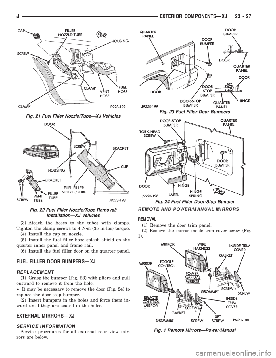
(3) Remove the cap from the nozzle (Fig. 21).
(3) Loosen the clamps and separate the hoses from
the tubes.
(4) Remove the screws that attach the nozzle to
the housing.
(5) Remove the nozzle/tube from the fuel filler
housing (Fig. 22).
INSTALLATION
(1) Insert the fuel filler nozzle/tube into the hous-
ing.
(2) Install the screws to attach the nozzle/tube to
the housing. Tighten screws to 2 Nzm (20 in-lbs)
torque.
Fig. 18 XJ Exterior Nameplates
Fig. 19 Fuel Filler DoorÐTypical
Fig. 20 Fuel Filler Hose Splash ShieldÐXJ Vehicles
23 - 26 EXTERIOR COMPONENTSÐXJJ
Page 1760 of 2198
(3) Attach the hoses to the tubes with clamps.
Tighten the clamp screws to 4 Nzm (35 in-lbs) torque.
(4) Install the cap on nozzle.
(5) Install the fuel filler hose splash shield on the
quarter inner panel and frame rail.
(6) Install the fuel filler door on the quarter panel.
FUEL FILLER DOOR BUMPERSÐXJ
REPLACEMENT
(1) Grasp the bumper (Fig. 23) with pliers and pull
outward to remove it from the hole.
²It may be necessary to remove the door (Fig. 24) to
replace the door-stop bumper.
(2) Insert bumpers in the holes and force them in-
ward until they are seated in the holes.
EXTERNAL MIRRORSÐXJ
SERVICE INFORMATION
Service procedures for all external rear view mir-
rors are below.
REMOTE AND POWER/MANUAL MIRRORS
REMOVAL
(1) Remove the door trim panel.
(2) Remove the mirror inside trim cover screw (Fig.
1).
Fig. 21 Fuel Filler Nozzle/TubeÐXJ Vehicles
Fig. 22 Fuel Filler Nozzle/Tube Removal/
InstallationÐXJ Vehicles
Fig. 23 Fuel Filler Door Bumpers
Fig. 24 Fuel Filler Door-Stop Bumper
Fig. 1 Remote MirrorsÐPower/Manual
JEXTERIOR COMPONENTSÐXJ 23 - 27