1995 JEEP CHEROKEE seat
[x] Cancel search: seatPage 1803 of 2198
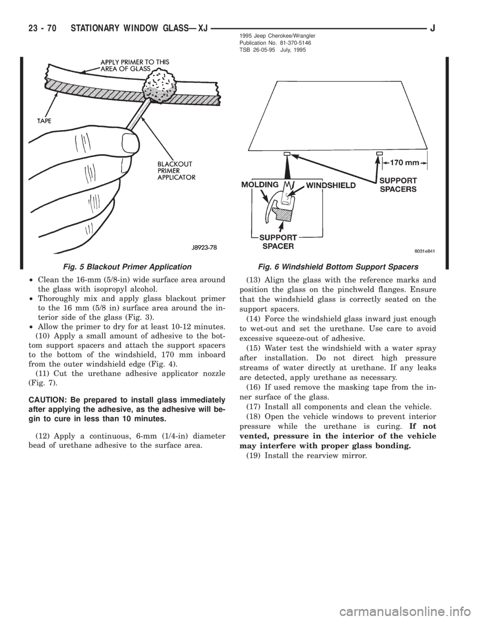
²Clean the 16-mm (5/8-in) wide surface area around
the glass with isopropyl alcohol.
²Thoroughly mix and apply glass blackout primer
to the 16 mm (5/8 in) surface area around the in-
terior side of the glass (Fig. 3).
²Allow the primer to dry for at least 10-12 minutes.
(10) Apply a small amount of adhesive to the bot-
tom support spacers and attach the support spacers
to the bottom of the windshield, 170 mm inboard
from the outer windshield edge (Fig. 4).
(11) Cut the urethane adhesive applicator nozzle
(Fig. 7).
CAUTION: Be prepared to install glass immediately
after applying the adhesive, as the adhesive will be-
gin to cure in less than 10 minutes.
(12) Apply a continuous, 6-mm (1/4-in) diameter
bead of urethane adhesive to the surface area.(13) Align the glass with the reference marks and
position the glass on the pinchweld flanges. Ensure
that the windshield glass is correctly seated on the
support spacers.
(14) Force the windshield glass inward just enough
to wet-out and set the urethane. Use care to avoid
excessive squeeze-out of adhesive.
(15) Water test the windshield with a water spray
after installation. Do not direct high pressure
streams of water directly at urethane. If any leaks
are detected, apply urethane as necessary.
(16) If used remove the masking tape from the in-
ner surface of the glass.
(17) Install all components and clean the vehicle.
(18) Open the vehicle windows to prevent interior
pressure while the urethane is curing.If not
vented, pressure in the interior of the vehicle
may interfere with proper glass bonding.
(19) Install the rearview mirror.
Fig. 6 Windshield Bottom Support SpacersFig. 5 Blackout Primer Application
23 - 70 STATIONARY WINDOW GLASSÐXJJ1995 Jeep Cherokee/Wrangler
Publication No. 81-370-5146
TSB 26-05-95 July, 1995
Page 1813 of 2198
INTERIOR COMPONENTS
INDEX
page page
Assist HandleÐXJ........................ 89
B/C-Pillar and Liftgate Pillar Trim CoversÐXJ.... 88
Bucket Seat Cushion and CoverÐXJ........... 81
Bucket Seat PlatformÐXJ................... 82
Bucket Seatback Cover and FrameÐXJ........ 81
Cargo BarrierÐXJ........................ 101
Cargo LampÐXJ......................... 94
Carpets and Floor MatsÐXJ................. 99
Dome LampÐXJ......................... 93
Front Bucket SeatsÐXJ.................... 81
Front Carpet/MatÐXJ...................... 99
Front Inner Scuff Plate/Cowl Side Trim PanelÐXJ . 86
Front Shoulder Belt/BuckleÐXJ............... 90
Full Floor ConsoleÐXJ..................... 95
HeadlinerÐXJ............................ 92
I/P Ash Receiver Tray LampÐXJ.............. 80
Instrument Cluster BezelÐXJ................ 80
Interior Trim Panels and Scuff PlatesÐXJ....... 84
Jack StorageÐXJ......................... 97
Keyless Entry ReceiverÐXJ................. 93Mini-Console with Floor ShiftÐXJ............. 94
Mini-Floor ConsoleÐXJ..................... 94
Outer Scuff PlatesÐXJ..................... 89
Overhead ConsoleÐXJ..................... 93
Parking Brake Handle CoverÐXJ............. 94
Quarter and Wheelhouse Trim PanelsÐXJ...... 87
Quarter Trim Panel ExtensionÐXJ............. 87
Rear Carpet/MatÐXJ..................... 100
Rear Seat Cushion CoverÐXJ............... 82
Rear Seat CushionÐXJ.................... 82
Rear Seatback CoverÐXJ................... 84
Rear Seatback Latch Striker and BumperÐXJ.... 84
Rear SeatbackÐXJ........................ 83
Rear Shoulder/Lap Belt/BuckleÐXJ............ 91
Sound BarÐXJ........................... 94
Spare Tire/Wheel Holddown and Floor
BracketsÐXJ........................... 98
SunvisorsÐXJ........................... 93
Windshield Side MoldingÐXJ................ 86
INSTRUMENT CLUSTER BEZELÐXJ
REMOVAL
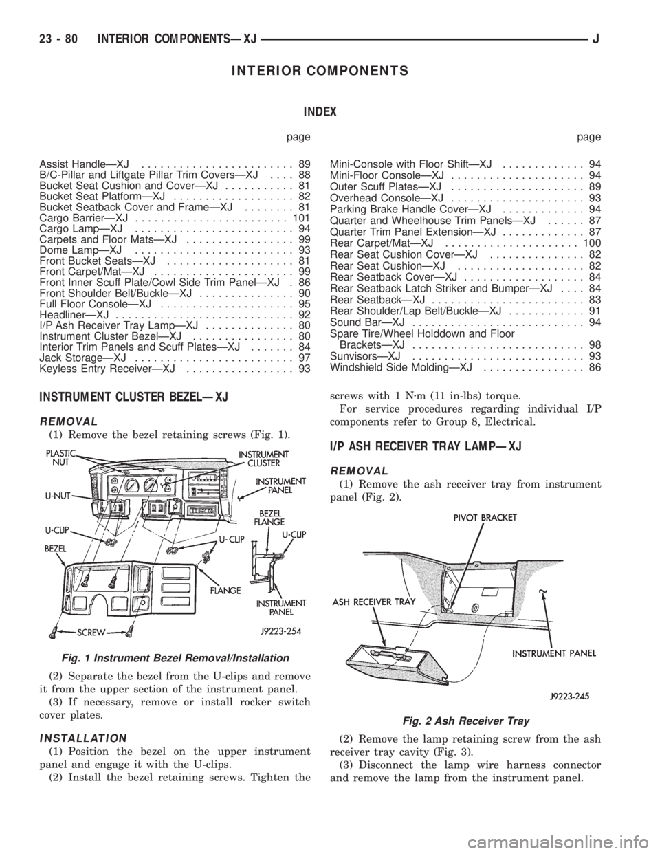
(1) Remove the bezel retaining screws (Fig. 1).
(2) Separate the bezel from the U-clips and remove
it from the upper section of the instrument panel.
(3) If necessary, remove or install rocker switch
cover plates.
INSTALLATION
(1) Position the bezel on the upper instrument
panel and engage it with the U-clips.
(2) Install the bezel retaining screws. Tighten thescrews with 1 Nzm (11 in-lbs) torque.
For service procedures regarding individual I/P
components refer to Group 8, Electrical.
I/P ASH RECEIVER TRAY LAMPÐXJ
REMOVAL
(1) Remove the ash receiver tray from instrument
panel (Fig. 2).
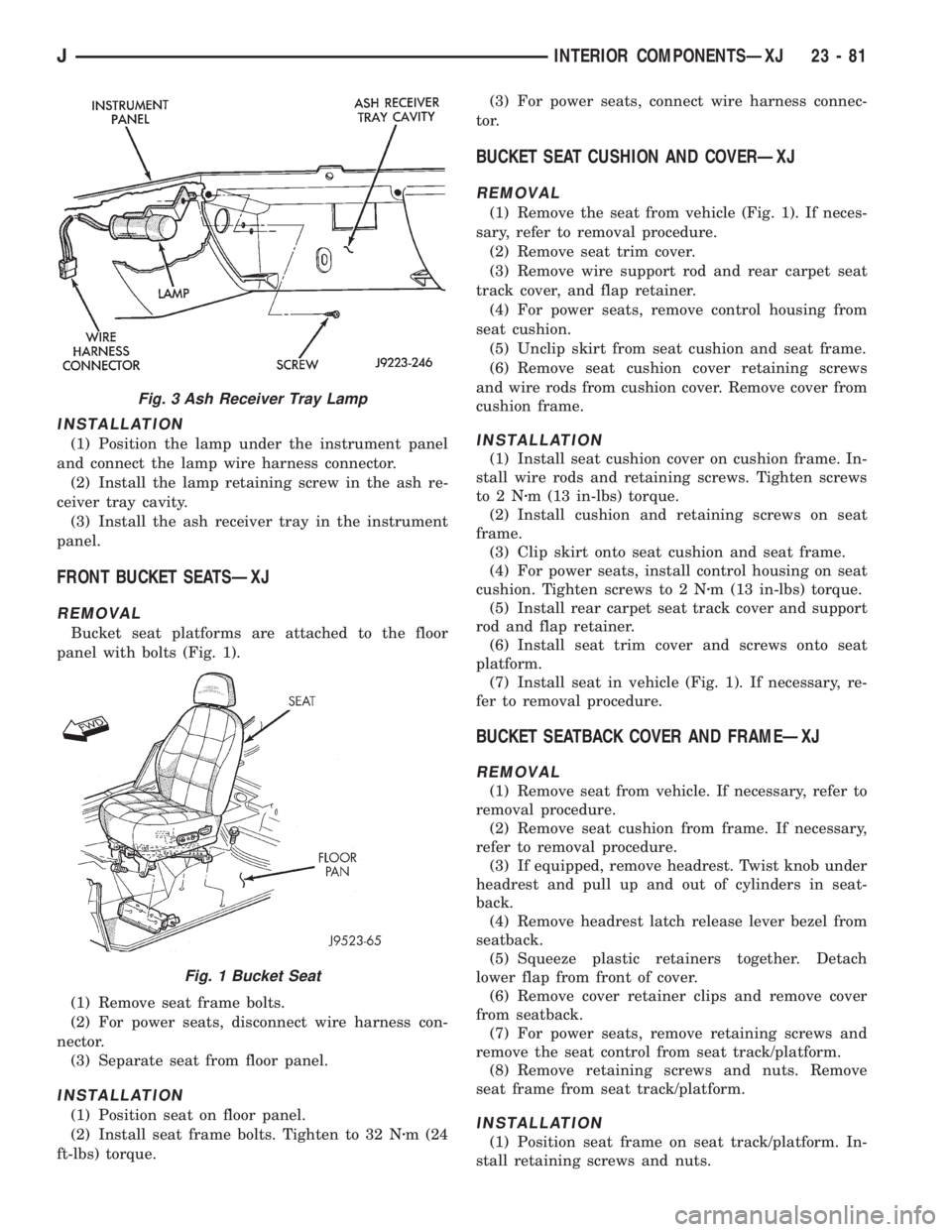
(2) Remove the lamp retaining screw from the ash
receiver tray cavity (Fig. 3).
(3) Disconnect the lamp wire harness connector
and remove the lamp from the instrument panel.
Fig. 1 Instrument Bezel Removal/Installation
Fig. 2 Ash Receiver Tray
23 - 80 INTERIOR COMPONENTSÐXJJ
Page 1814 of 2198
INSTALLATION
(1) Position the lamp under the instrument panel
and connect the lamp wire harness connector.
(2) Install the lamp retaining screw in the ash re-
ceiver tray cavity.
(3) Install the ash receiver tray in the instrument
panel.
FRONT BUCKET SEATSÐXJ
REMOVAL
Bucket seat platforms are attached to the floor
panel with bolts (Fig. 1).
(1) Remove seat frame bolts.
(2) For power seats, disconnect wire harness con-
nector.
(3) Separate seat from floor panel.
INSTALLATION
(1) Position seat on floor panel.
(2) Install seat frame bolts. Tighten to 32 Nzm (24
ft-lbs) torque.(3) For power seats, connect wire harness connec-
tor.
BUCKET SEAT CUSHION AND COVERÐXJ
REMOVAL
(1) Remove the seat from vehicle (Fig. 1). If neces-
sary, refer to removal procedure.
(2) Remove seat trim cover.
(3) Remove wire support rod and rear carpet seat
track cover, and flap retainer.
(4) For power seats, remove control housing from
seat cushion.
(5) Unclip skirt from seat cushion and seat frame.
(6) Remove seat cushion cover retaining screws
and wire rods from cushion cover. Remove cover from
cushion frame.
INSTALLATION
(1) Install seat cushion cover on cushion frame. In-
stall wire rods and retaining screws. Tighten screws
to2Nzm (13 in-lbs) torque.
(2) Install cushion and retaining screws on seat
frame.
(3) Clip skirt onto seat cushion and seat frame.
(4) For power seats, install control housing on seat
cushion. Tighten screws to 2 Nzm (13 in-lbs) torque.
(5) Install rear carpet seat track cover and support
rod and flap retainer.
(6) Install seat trim cover and screws onto seat
platform.
(7) Install seat in vehicle (Fig. 1). If necessary, re-
fer to removal procedure.
BUCKET SEATBACK COVER AND FRAMEÐXJ
REMOVAL
(1) Remove seat from vehicle. If necessary, refer to
removal procedure.
(2) Remove seat cushion from frame. If necessary,
refer to removal procedure.
(3) If equipped, remove headrest. Twist knob under
headrest and pull up and out of cylinders in seat-
back.
(4) Remove headrest latch release lever bezel from
seatback.
(5) Squeeze plastic retainers together. Detach
lower flap from front of cover.
(6) Remove cover retainer clips and remove cover
from seatback.
(7) For power seats, remove retaining screws and
remove the seat control from seat track/platform.
(8) Remove retaining screws and nuts. Remove
seat frame from seat track/platform.
INSTALLATION
(1) Position seat frame on seat track/platform. In-
stall retaining screws and nuts.
Fig. 3 Ash Receiver Tray Lamp
Fig. 1 Bucket Seat
JINTERIOR COMPONENTSÐXJ 23 - 81
Page 1815 of 2198
(2) For power seats, position seat control on seat
track/platform. Install retaining screws. Tighten
screws securely.
(3) Position cover on seatback. Install cover re-
tainer clips.
(4) Attach cover bottom elastic band or attach Vel-
cro flap to front of cover.
(5) Install seatback insert.
(6) Install headrest latch release lever bezel.
(7) Install headrest by pushing it down into seat-
back cylinders.
(8) Install cushion on frame. If necessary, refer to
installation procedure.
(9) Install seat in the vehicle. If necessary, refer to
the installation procedure.
(10) For power seats, test seat operation.
BUCKET SEAT PLATFORMÐXJ
REPLACEMENT
Bucket seat platforms are not repairable. If the
seat platform is damaged, replace platform as a unit.
REAR SEAT CUSHIONÐXJ
REMOVAL
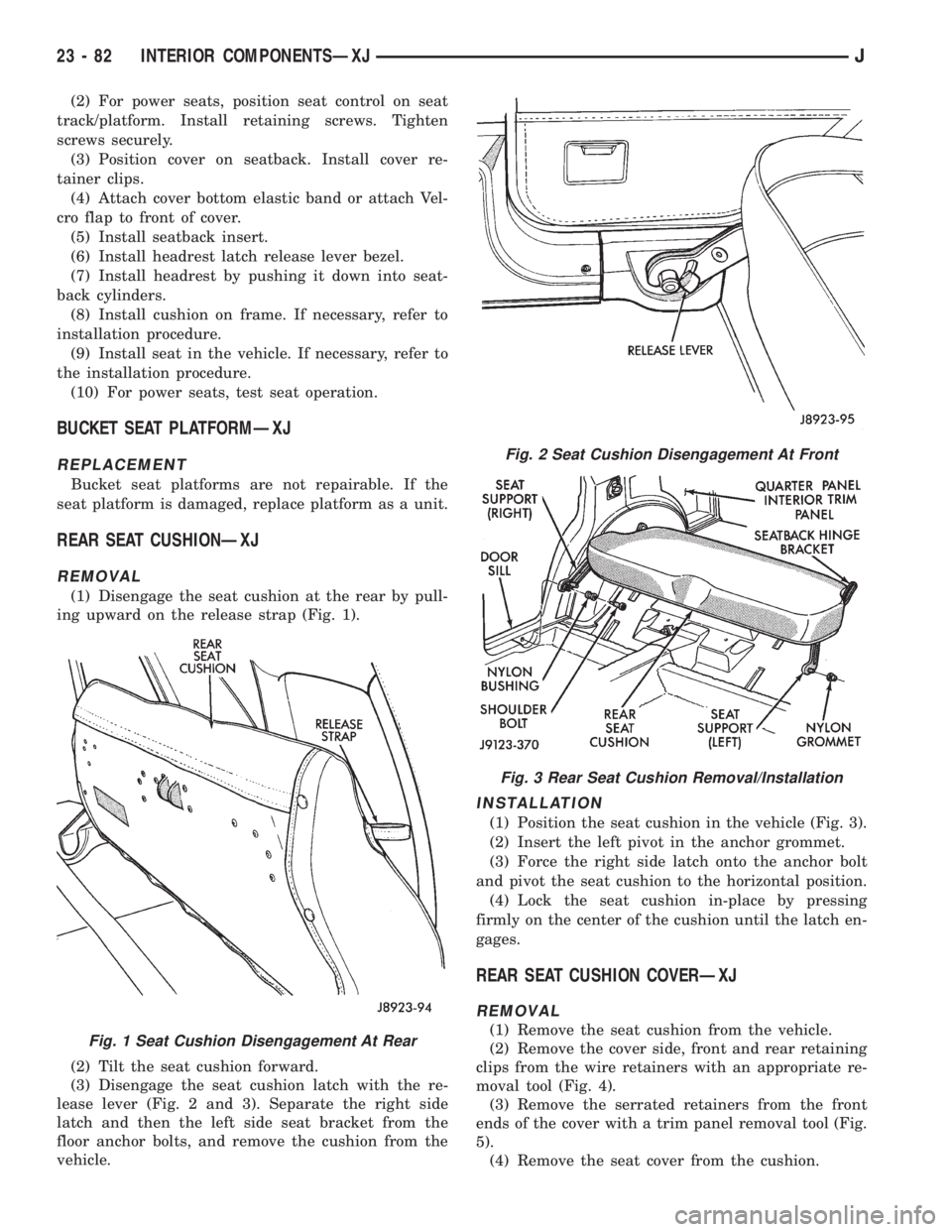
(1) Disengage the seat cushion at the rear by pull-
ing upward on the release strap (Fig. 1).
(2) Tilt the seat cushion forward.
(3) Disengage the seat cushion latch with the re-
lease lever (Fig. 2 and 3). Separate the right side
latch and then the left side seat bracket from the
floor anchor bolts, and remove the cushion from the
vehicle.
INSTALLATION
(1) Position the seat cushion in the vehicle (Fig. 3).
(2) Insert the left pivot in the anchor grommet.
(3) Force the right side latch onto the anchor bolt
and pivot the seat cushion to the horizontal position.
(4) Lock the seat cushion in-place by pressing
firmly on the center of the cushion until the latch en-
gages.
REAR SEAT CUSHION COVERÐXJ
REMOVAL
(1) Remove the seat cushion from the vehicle.
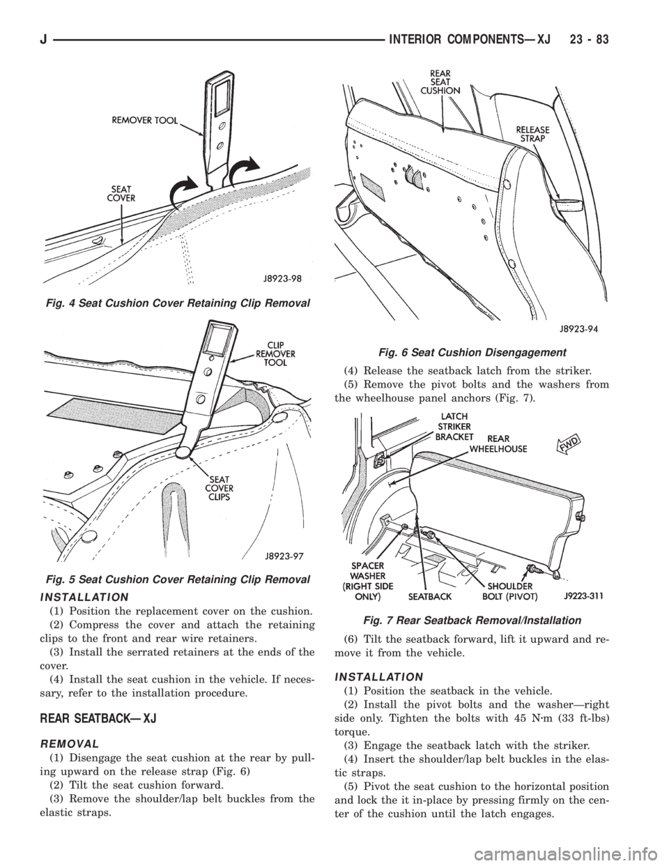
(2) Remove the cover side, front and rear retaining
clips from the wire retainers with an appropriate re-
moval tool (Fig. 4).
(3) Remove the serrated retainers from the front
ends of the cover with a trim panel removal tool (Fig.
5).
(4) Remove the seat cover from the cushion.Fig. 1 Seat Cushion Disengagement At Rear
Fig. 2 Seat Cushion Disengagement At Front
Fig. 3 Rear Seat Cushion Removal/Installation
23 - 82 INTERIOR COMPONENTSÐXJJ
Page 1816 of 2198
INSTALLATION
(1) Position the replacement cover on the cushion.
(2) Compress the cover and attach the retaining
clips to the front and rear wire retainers.
(3) Install the serrated retainers at the ends of the
cover.
(4) Install the seat cushion in the vehicle. If neces-
sary, refer to the installation procedure.
REAR SEATBACKÐXJ
REMOVAL
(1) Disengage the seat cushion at the rear by pull-
ing upward on the release strap (Fig. 6)
(2) Tilt the seat cushion forward.
(3) Remove the shoulder/lap belt buckles from the
elastic straps.(4) Release the seatback latch from the striker.
(5) Remove the pivot bolts and the washers from
the wheelhouse panel anchors (Fig. 7).
(6) Tilt the seatback forward, lift it upward and re-
move it from the vehicle.
INSTALLATION
(1) Position the seatback in the vehicle.
(2) Install the pivot bolts and the washerÐright
side only. Tighten the bolts with 45 Nzm (33 ft-lbs)
torque.
(3) Engage the seatback latch with the striker.
(4) Insert the shoulder/lap belt buckles in the elas-
tic straps.
(5) Pivot the seat cushion to the horizontal position
and lock the it in-place by pressing firmly on the cen-
ter of the cushion until the latch engages.
Fig. 4 Seat Cushion Cover Retaining Clip Removal
Fig. 5 Seat Cushion Cover Retaining Clip Removal
Fig. 6 Seat Cushion Disengagement
Fig. 7 Rear Seatback Removal/Installation
JINTERIOR COMPONENTSÐXJ 23 - 83
Page 1817 of 2198
REAR SEATBACK LATCH STRIKER AND BUMPERÐ
XJ
REMOVAL
(1) Disengage the seat cushion at the rear by pull-
ing upward on the release strap.
(2) Tilt the seat cushion forward.
(3) Release the seatback latch from the striker.
(4) Tilt the seatback forward for access to the
striker bracket.
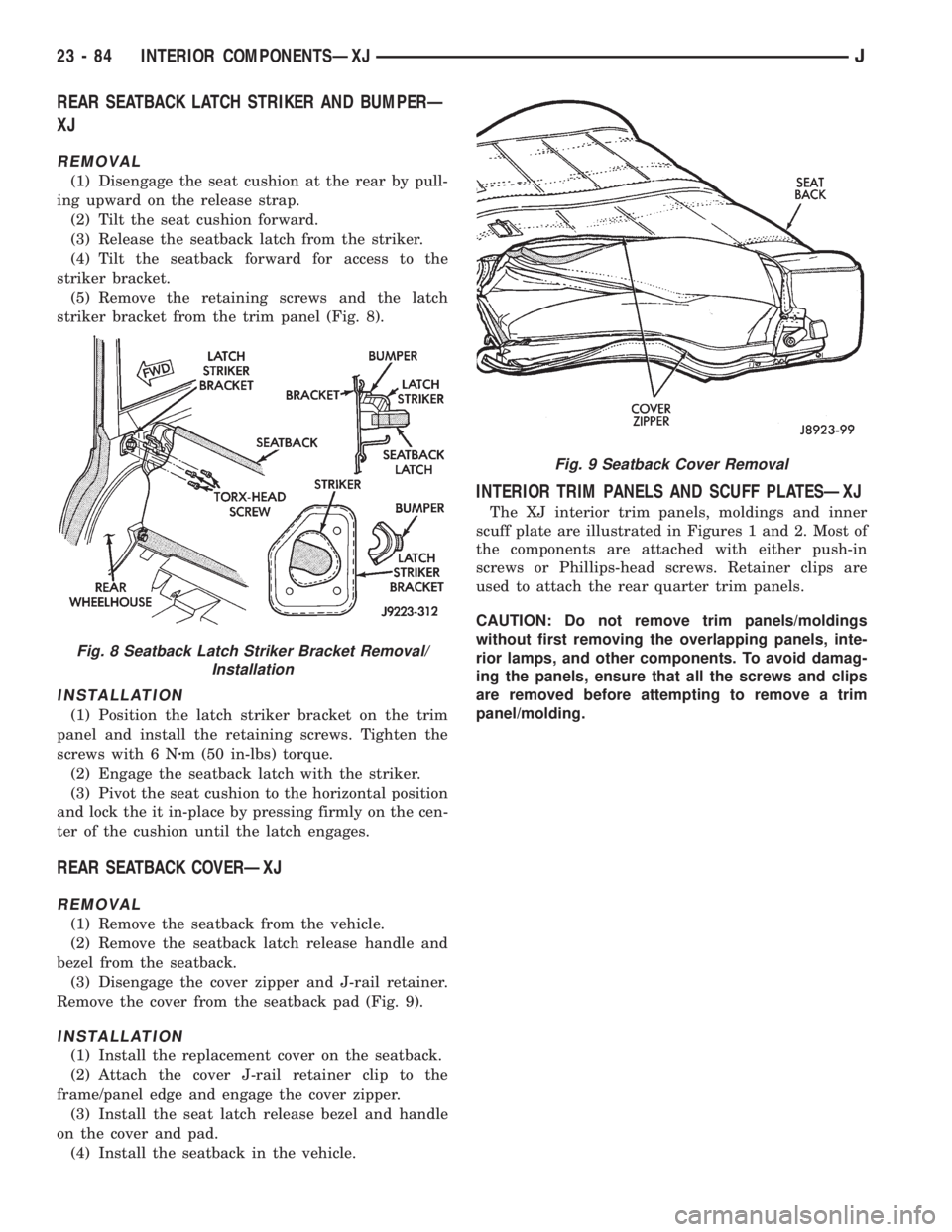
(5) Remove the retaining screws and the latch
striker bracket from the trim panel (Fig. 8).
INSTALLATION
(1) Position the latch striker bracket on the trim
panel and install the retaining screws. Tighten the
screws with 6 Nzm (50 in-lbs) torque.
(2) Engage the seatback latch with the striker.
(3) Pivot the seat cushion to the horizontal position
and lock the it in-place by pressing firmly on the cen-
ter of the cushion until the latch engages.
REAR SEATBACK COVERÐXJ
REMOVAL
(1) Remove the seatback from the vehicle.
(2) Remove the seatback latch release handle and
bezel from the seatback.
(3) Disengage the cover zipper and J-rail retainer.
Remove the cover from the seatback pad (Fig. 9).
INSTALLATION
(1) Install the replacement cover on the seatback.
(2) Attach the cover J-rail retainer clip to the
frame/panel edge and engage the cover zipper.
(3) Install the seat latch release bezel and handle
on the cover and pad.
(4) Install the seatback in the vehicle.
INTERIOR TRIM PANELS AND SCUFF PLATESÐXJ
The XJ interior trim panels, moldings and inner
scuff plate are illustrated in Figures 1 and 2. Most of
the components are attached with either push-in
screws or Phillips-head screws. Retainer clips are
used to attach the rear quarter trim panels.
CAUTION: Do not remove trim panels/moldings
without first removing the overlapping panels, inte-
rior lamps, and other components. To avoid damag-
ing the panels, ensure that all the screws and clips
are removed before attempting to remove a trim
panel/molding.
Fig. 8 Seatback Latch Striker Bracket Removal/
Installation
Fig. 9 Seatback Cover Removal
23 - 84 INTERIOR COMPONENTSÐXJJ
Page 1823 of 2198
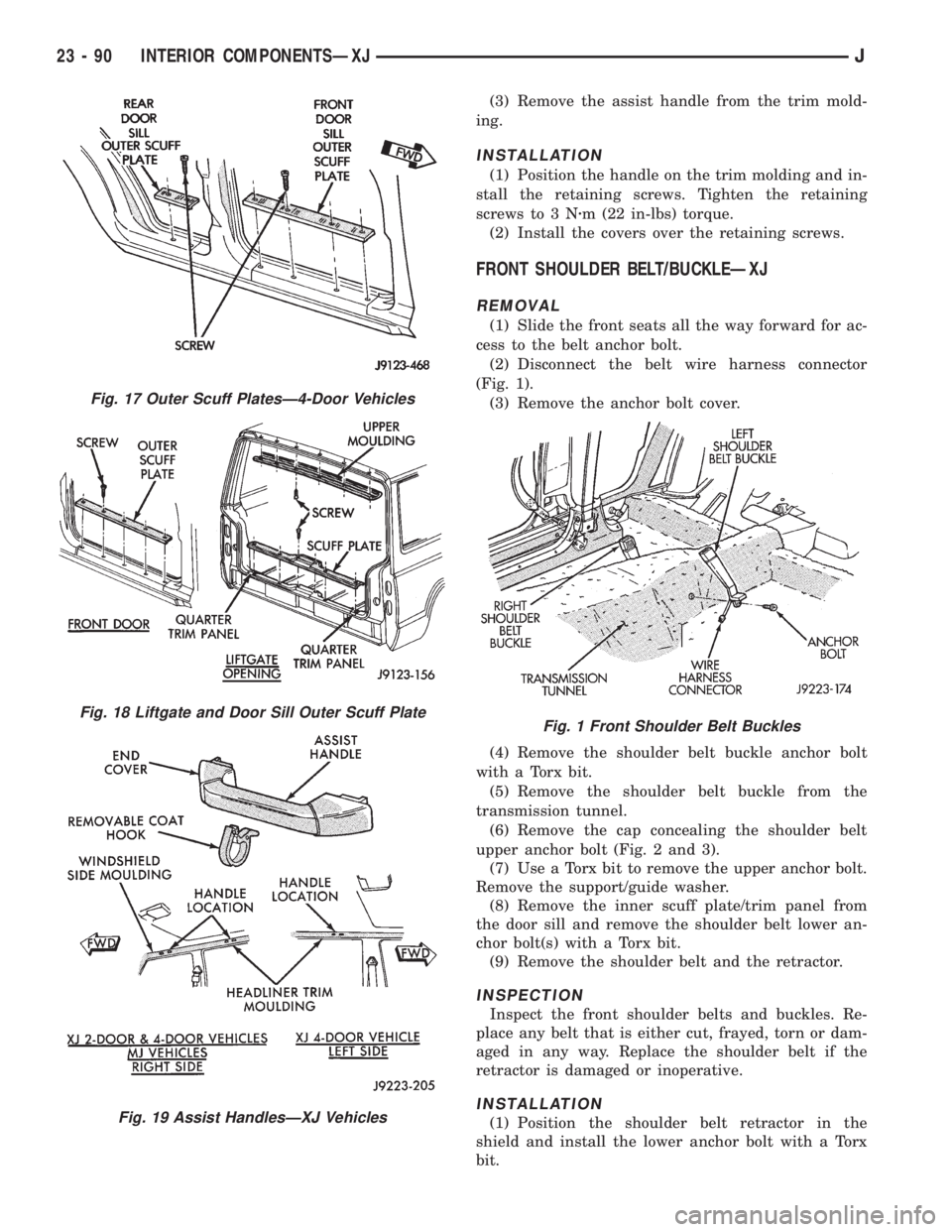
(3) Remove the assist handle from the trim mold-
ing.
INSTALLATION
(1) Position the handle on the trim molding and in-
stall the retaining screws. Tighten the retaining
screws to 3 Nzm (22 in-lbs) torque.
(2) Install the covers over the retaining screws.
FRONT SHOULDER BELT/BUCKLEÐXJ
REMOVAL
(1) Slide the front seats all the way forward for ac-
cess to the belt anchor bolt.
(2) Disconnect the belt wire harness connector
(Fig. 1).
(3) Remove the anchor bolt cover.
(4) Remove the shoulder belt buckle anchor bolt
with a Torx bit.
(5) Remove the shoulder belt buckle from the
transmission tunnel.
(6) Remove the cap concealing the shoulder belt
upper anchor bolt (Fig. 2 and 3).
(7) Use a Torx bit to remove the upper anchor bolt.
Remove the support/guide washer.
(8) Remove the inner scuff plate/trim panel from
the door sill and remove the shoulder belt lower an-
chor bolt(s) with a Torx bit.
(9) Remove the shoulder belt and the retractor.
INSPECTION
Inspect the front shoulder belts and buckles. Re-
place any belt that is either cut, frayed, torn or dam-
aged in any way. Replace the shoulder belt if the
retractor is damaged or inoperative.
INSTALLATION
(1) Position the shoulder belt retractor in the
shield and install the lower anchor bolt with a Torx
bit.
Fig. 17 Outer Scuff PlatesÐ4-Door Vehicles
Fig. 18 Liftgate and Door Sill Outer Scuff Plate
Fig. 19 Assist HandlesÐXJ Vehicles
Fig. 1 Front Shoulder Belt Buckles
23 - 90 INTERIOR COMPONENTSÐXJJ
Page 1824 of 2198
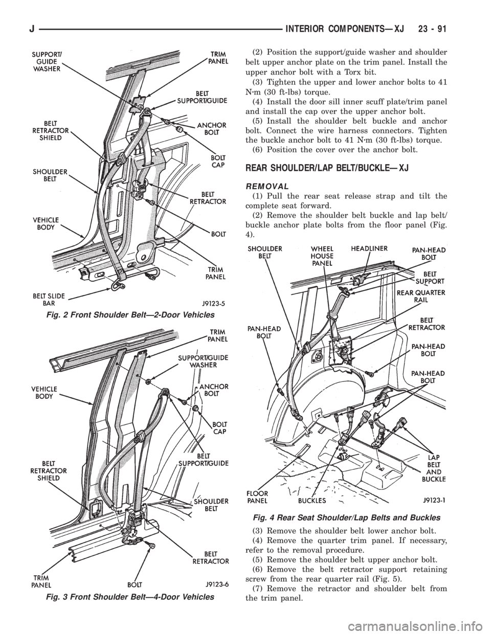
(2) Position the support/guide washer and shoulder
belt upper anchor plate on the trim panel. Install the
upper anchor bolt with a Torx bit.
(3) Tighten the upper and lower anchor bolts to 41
Nzm (30 ft-lbs) torque.
(4) Install the door sill inner scuff plate/trim panel
and install the cap over the upper anchor bolt.
(5) Install the shoulder belt buckle and anchor
bolt. Connect the wire harness connectors. Tighten
the buckle anchor bolt to 41 Nzm (30 ft-lbs) torque.
(6) Position the cover over the anchor bolt.
REAR SHOULDER/LAP BELT/BUCKLEÐXJ
REMOVAL
(1) Pull the rear seat release strap and tilt the
complete seat forward.
(2) Remove the shoulder belt buckle and lap belt/
buckle anchor plate bolts from the floor panel (Fig.
4).
(3) Remove the shoulder belt lower anchor bolt.
(4) Remove the quarter trim panel. If necessary,
refer to the removal procedure.
(5) Remove the shoulder belt upper anchor bolt.
(6) Remove the belt retractor support retaining
screw from the rear quarter rail (Fig. 5).
(7) Remove the retractor and shoulder belt from
the trim panel.
Fig. 2 Front Shoulder BeltÐ2-Door Vehicles
Fig. 3 Front Shoulder BeltÐ4-Door Vehicles
Fig. 4 Rear Seat Shoulder/Lap Belts and Buckles
JINTERIOR COMPONENTSÐXJ 23 - 91