1995 JEEP CHEROKEE wire diagram
[x] Cancel search: wire diagramPage 296 of 2198
BATTERY/STARTER/GENERATOR SERVICE
CONTENTS
page page
BATTERY............................... 1
GENERATOR............................ 6SPECIFICATIONS......................... 8
STARTER AND STARTER RELAY............. 4
GENERAL INFORMATION
Group 8B covers battery, starter and generator ser-
vice procedures. For diagnosis of these components
and their related systems, refer to Group 8A - Bat-tery/Starting/Charging Systems Diagnostics. Refer to
Group 8W - Wiring Diagrams for complete circuit de-
scriptions and diagrams.
BATTERY
GENERAL INFORMATION
This section covers battery service procedures only.
For battery maintenance procedures, refer to Group 0
- Lubrication and Maintenance. While battery charg-
ing can be considered a service or maintenance pro-
cedure, this information is located in Group 8A -
Battery/Starting/Charging Systems Diagnostics. This
was done because the battery must be fully charged
before any diagnosis is performed.
It is important that the battery, starting, and
charging systems be thoroughly tested and inspected
any time a battery needs to be charged or replaced.
The cause of abnormal discharge, over-charging, or
premature failure of the battery must be diagnosed
and corrected before a battery is replaced or returned
to service. Refer to Group 8A - Battery/Starting/
Charging Systems Diagnostics.
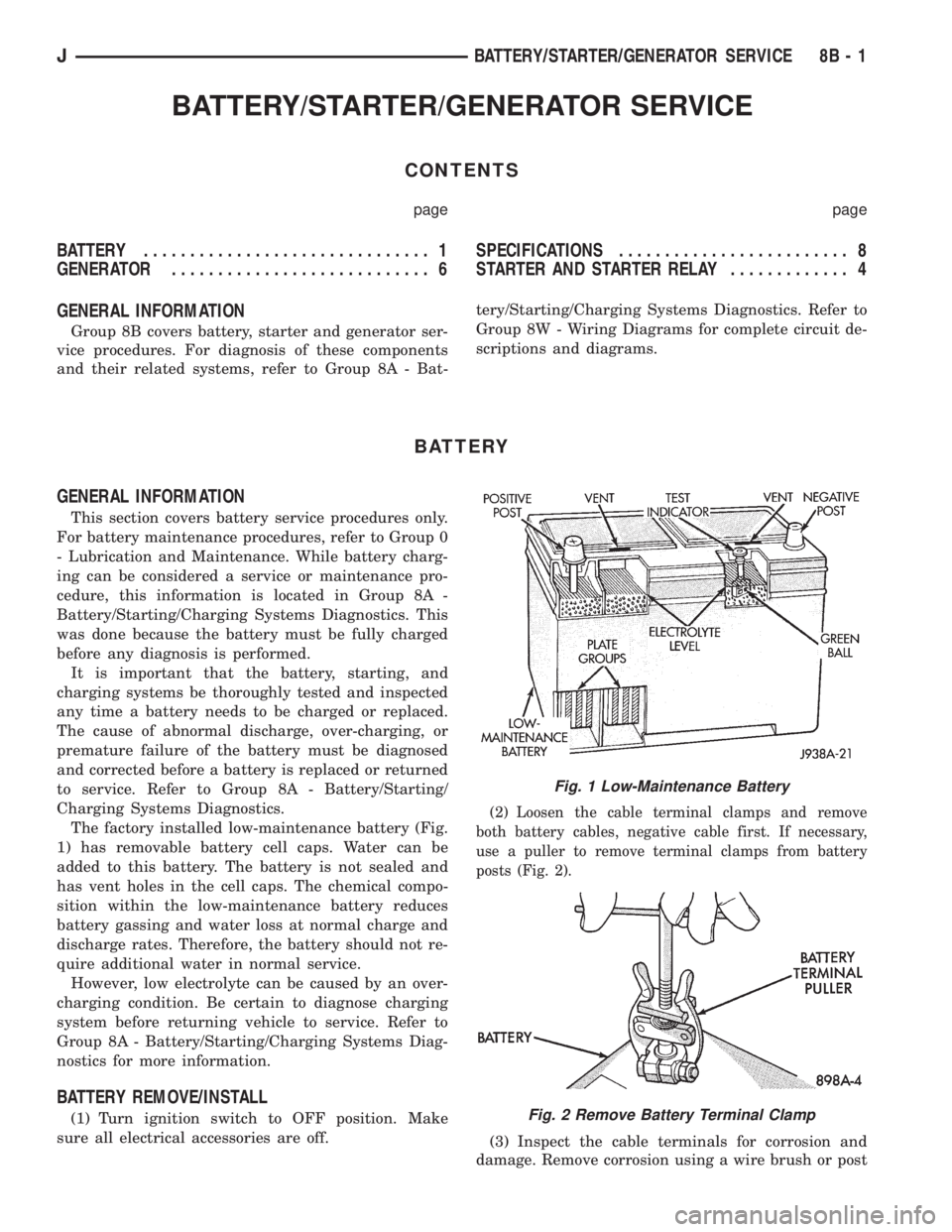
The factory installed low-maintenance battery (Fig.
1) has removable battery cell caps. Water can be
added to this battery. The battery is not sealed and
has vent holes in the cell caps. The chemical compo-
sition within the low-maintenance battery reduces
battery gassing and water loss at normal charge and
discharge rates. Therefore, the battery should not re-
quire additional water in normal service.
However, low electrolyte can be caused by an over-
charging condition. Be certain to diagnose charging
system before returning vehicle to service. Refer to
Group 8A - Battery/Starting/Charging Systems Diag-
nostics for more information.
BATTERY REMOVE/INSTALL
(1) Turn ignition switch to OFF position. Make
sure all electrical accessories are off.
(2) Loosen the cable terminal clamps and remove
both battery cables, negative cable first. If necessary,
use a puller to remove terminal clamps from battery
posts (Fig. 2).
(3) Inspect the cable terminals for corrosion and
damage. Remove corrosion using a wire brush or post
Fig. 1 Low-Maintenance Battery
Fig. 2 Remove Battery Terminal Clamp
JBATTERY/STARTER/GENERATOR SERVICE 8B - 1
Page 317 of 2198

DIAGNOSTICS/SERVICE PROCEDURES
INDEX
page page
Automatic Shutdown (ASD) Relay Test.......... 6
Camshaft Position Sensor Test................ 6
Crankshaft Position Sensor Test............... 7
Distributor Cap............................ 7
Distributor Rotor........................... 8
DRB Scan Tool............................ 8
Engine Coolant Temperature Sensor Test........ 9
General Information........................ 6
Ignition Coil.............................. 9
Ignition Secondary Circuit Diagnosis........... 10Ignition Timing............................ 11
Intake Manifold Air Temperature Sensor Test..... 11
Manifold Absolute Pressure (MAP) Sensor Test . . . 11
On-Board Diagnostics...................... 15
Oxygen (O2S) Sensor Tests................. 15
Powertrain Control Module (PCM)............. 11
Spark Plug Secondary Cables................ 14
Spark Plugs............................. 12
Throttle Position Sensor Test................. 15
GENERAL INFORMATION
This section of the group, Diagnostics/Service Pro-
cedures, will discuss basic ignition system diagnostics
and service adjustments.
For system operation and component identification,
refer to the Component Identification/System Opera-
tion section of this group.
For removal or installation of ignition system com-
ponents, refer to the Component Removal/Installa-
tion section of this group.
For other useful information, refer to the On-Board
Diagnostics section.
For operation of the DRB Scan Tool, refer to the
appropriate Powertrain Diagnostic Procedures ser-
vice manual.
AUTOMATIC SHUTDOWN (ASD) RELAY TEST
To perform a complete test of this relay and its cir-
cuitry, refer to the DRB scan tool. Also refer to the
appropriate Powertrain Diagnostics Procedures man-
ual. To test the relay only, refer to RelaysÐOpera-
tion/Testing in the Group 14, Fuel Systems section.
CAMSHAFT POSITION SENSOR TEST
To perform a complete test of this sensor and its
circuitry, refer to the DRB scan tool. Also refer to the
appropriate Powertrain Diagnostics Procedures man-
ual. To test the sensor only, refer to the following:
The camshaft position sensor is located in the dis-
tributor (Fig. 1).
To perform a complete test of this sensor and its
circuitry, refer to the DRB scan tool. Also refer to the
appropriate Powertrain Diagnostics Procedures man-
ual. To test the sensor only, refer to the following:
For this test, an analog (non-digital) voltme-
ter is needed.Do not remove the distributor connec-
tor from the distributor. Using small paper clips,
insert them into the backside of the distributor wire
harness connector to make contact with the termi-nals. Be sure that the connector is not damaged
when inserting the paper clips. Attach voltmeter
leads to these paper clips.
(1) Connect the positive (+) voltmeter lead into the
sensor output wire. This is at done the distributor
wire harness connector. For wire identification, refer
to Group 8W, Wiring Diagrams.
(2) Connect the negative (-) voltmeter lead into the
ground wire. For wire identification, refer to Group
8W, Wiring Diagrams.
(3) Set the voltmeter to the 15 Volt DC scale.
(4) Remove distributor cap from distributor (two
screws). Rotate (crank) the engine until the distribu-
tor rotor is pointed to approximately the 11 o'clock
position. The movable pulse ring should now be
within the sensor pickup.
(5) Turn ignition key to ON position. The voltmeter
should read approximately 5.0 volts.
(6) If voltage is not present, check the voltmeter
leads for a good connection.
(7) If voltage is still not present, check for voltage
at the supply wire. For wire identification, refer to
Group 8W, Wiring Diagrams.
Fig. 1 Camshaft Position SensorÐTypical
8D - 6 IGNITION SYSTEMSJ
Page 321 of 2198
IGNITION SECONDARY CIRCUIT DIAGNOSIS
CHECKING FOR SPARK
CAUTION: When disconnecting a high voltage cable
from a spark plug or from the distributor cap, twist
the rubber boot slightly (1/2 turn) to break it loose
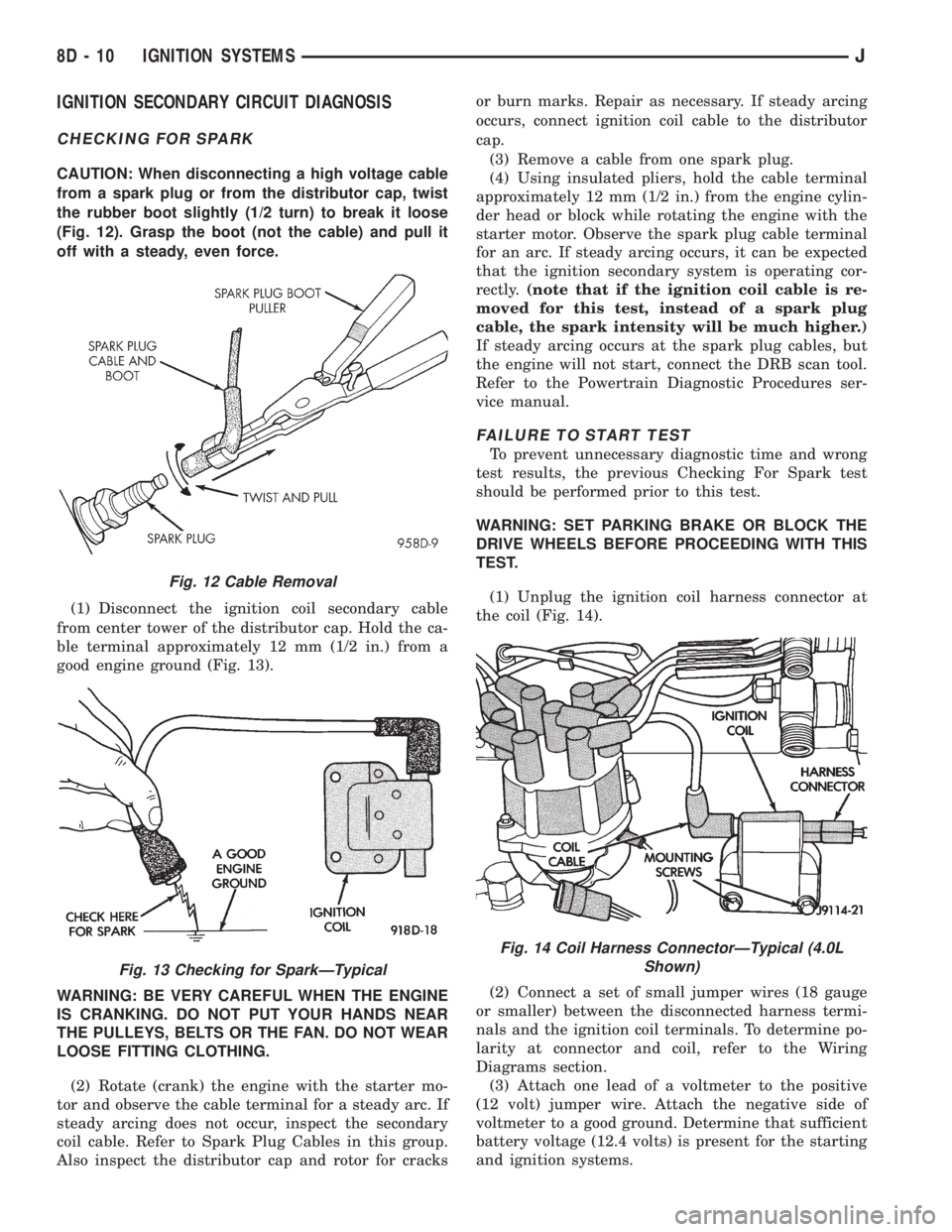
(Fig. 12). Grasp the boot (not the cable) and pull it
off with a steady, even force.
(1) Disconnect the ignition coil secondary cable
from center tower of the distributor cap. Hold the ca-
ble terminal approximately 12 mm (1/2 in.) from a
good engine ground (Fig. 13).
WARNING: BE VERY CAREFUL WHEN THE ENGINE
IS CRANKING. DO NOT PUT YOUR HANDS NEAR
THE PULLEYS, BELTS OR THE FAN. DO NOT WEAR
LOOSE FITTING CLOTHING.
(2) Rotate (crank) the engine with the starter mo-
tor and observe the cable terminal for a steady arc. If
steady arcing does not occur, inspect the secondary
coil cable. Refer to Spark Plug Cables in this group.
Also inspect the distributor cap and rotor for cracksor burn marks. Repair as necessary. If steady arcing
occurs, connect ignition coil cable to the distributor
cap.
(3) Remove a cable from one spark plug.
(4) Using insulated pliers, hold the cable terminal
approximately 12 mm (1/2 in.) from the engine cylin-
der head or block while rotating the engine with the
starter motor. Observe the spark plug cable terminal
for an arc. If steady arcing occurs, it can be expected
that the ignition secondary system is operating cor-
rectly.(note that if the ignition coil cable is re-
moved for this test, instead of a spark plug
cable, the spark intensity will be much higher.)
If steady arcing occurs at the spark plug cables, but
the engine will not start, connect the DRB scan tool.
Refer to the Powertrain Diagnostic Procedures ser-
vice manual.
FAILURE TO START TEST
To prevent unnecessary diagnostic time and wrong
test results, the previous Checking For Spark test
should be performed prior to this test.
WARNING: SET PARKING BRAKE OR BLOCK THE
DRIVE WHEELS BEFORE PROCEEDING WITH THIS
TEST.
(1) Unplug the ignition coil harness connector at
the coil (Fig. 14).
(2) Connect a set of small jumper wires (18 gauge
or smaller) between the disconnected harness termi-
nals and the ignition coil terminals. To determine po-
larity at connector and coil, refer to the Wiring
Diagrams section.
(3) Attach one lead of a voltmeter to the positive
(12 volt) jumper wire. Attach the negative side of
voltmeter to a good ground. Determine that sufficient
battery voltage (12.4 volts) is present for the starting
and ignition systems.
Fig. 12 Cable Removal
Fig. 13 Checking for SparkÐTypical
Fig. 14 Coil Harness ConnectorÐTypical (4.0L
Shown)
8D - 10 IGNITION SYSTEMSJ
Page 425 of 2198
WINDSHIELD WASHER SYSTEM
WITH NON-INTERMITTENT WIPE
(1) Unplug washer pump connector. Measure resis-
tance between terminal B at pump and a clean chas-
sis ground. Meter should read zero ohms. If not OK,
repair open to ground.
(2) Turn ignition switch to ACCESSORY and
washer (multi-function) switch to ON.
(a) Measure voltage at washer pump connector
terminal A. Meter should read battery voltage. If
OK, replace washer pump. If not OK, go to next
step.
(b) Measure voltage at wiper/washer switch con-
nector terminal B. Meter should read battery volt-
age. If OK, repair open to washer pump. If not OK,
replace switch.
WITH INTERMITTENT WIPE
(1) Unplug washer pump connector. Measure resis-
tance between terminal B at pump and a clean chas-
sis ground. Meter should read zero ohms. If not OK,
repair open to ground.
(2) Turn ignition switch to ACCESSORY and
washer (multi-function) switch to ON.
(a) Measure voltage at intermittent wipe module
switch connector terminal B (pink wire). Meter
should read battery voltage. If not OK, replace
wiper switch.
(b) Measure voltage at wipe module motor con-
nector terminal B (brown wire). Meter should read
battery voltage. If not OK, replace module.
(c) Measure voltage at washer pump connector
terminal A at pump. Meter should read battery
voltage. If OK, replace pump. If not OK, repair
open from wipe module.
WINDSHIELD WIPER/WASHER SWITCH
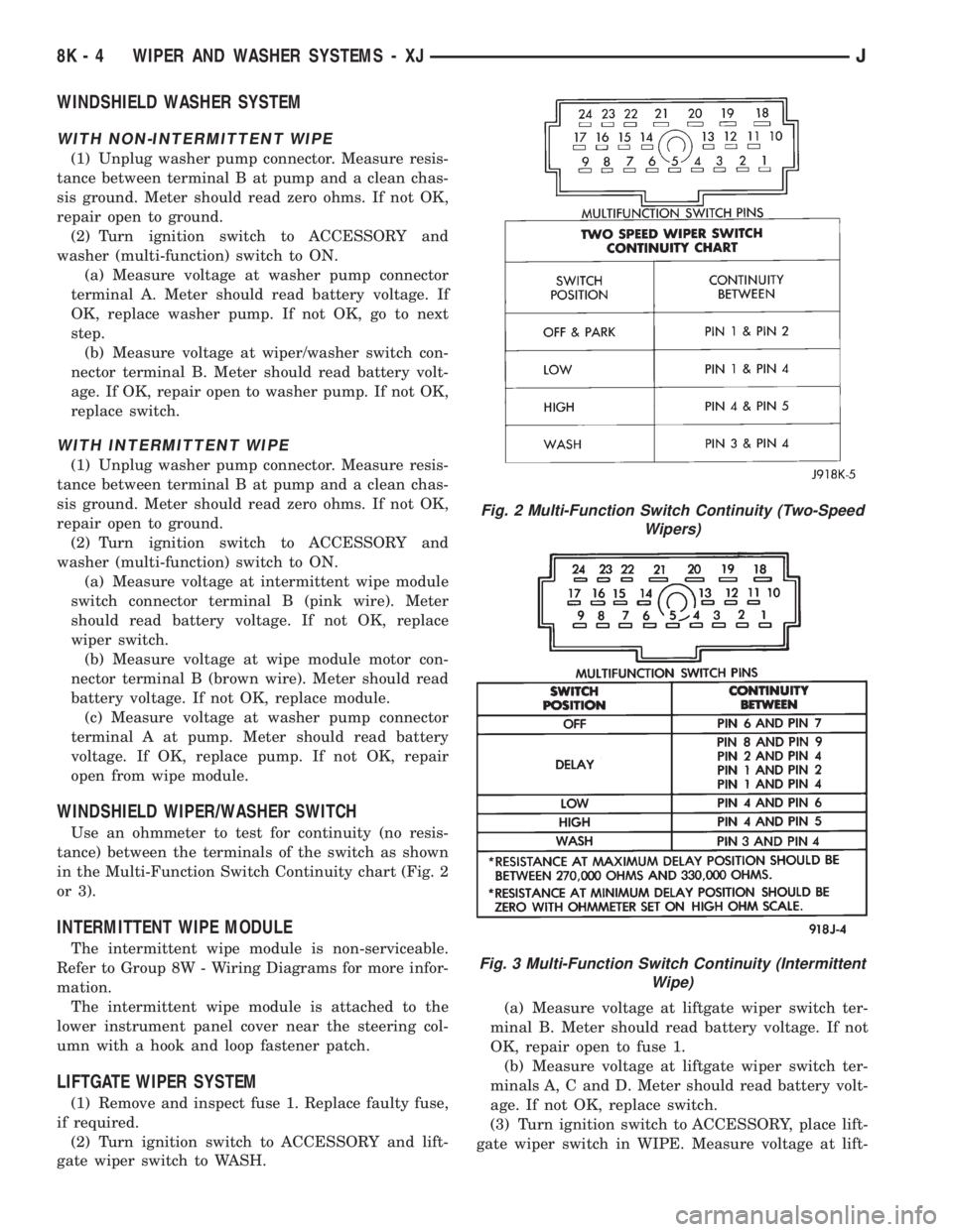
Use an ohmmeter to test for continuity (no resis-
tance) between the terminals of the switch as shown
in the Multi-Function Switch Continuity chart (Fig. 2
or 3).
INTERMITTENT WIPE MODULE
The intermittent wipe module is non-serviceable.
Refer to Group 8W - Wiring Diagrams for more infor-
mation.
The intermittent wipe module is attached to the
lower instrument panel cover near the steering col-
umn with a hook and loop fastener patch.
LIFTGATE WIPER SYSTEM
(1) Remove and inspect fuse 1. Replace faulty fuse,
if required.
(2) Turn ignition switch to ACCESSORY and lift-
gate wiper switch to WASH.(a) Measure voltage at liftgate wiper switch ter-
minal B. Meter should read battery voltage. If not
OK, repair open to fuse 1.
(b) Measure voltage at liftgate wiper switch ter-
minals A, C and D. Meter should read battery volt-
age. If not OK, replace switch.
(3) Turn ignition switch to ACCESSORY, place lift-
gate wiper switch in WIPE. Measure voltage at lift-
Fig. 2 Multi-Function Switch Continuity (Two-Speed
Wipers)
Fig. 3 Multi-Function Switch Continuity (Intermittent
Wipe)
8K - 4 WIPER AND WASHER SYSTEMS - XJJ
Page 437 of 2198
LIFTGATE WIPER/WASHER SYSTEM
(1) Turn ignition switch to ON and liftgate wiper/
washer switch to WASH.
(a) Measure voltage at switch connector terminal
P. Meter should read battery voltage. If not OK,
check fuse 1.
(b) Measure voltage at switch connector terminal
B. Meter should read battery voltage. If not OK, re-
place switch.
(c) Measure voltage at switch connector terminal
A. Meter should read battery voltage. If not OK, re-
place switch.
(2) Unplug liftgate washer pump connector.
(a) With ignition switch in OFF position, mea-
sure resistance at pump connector black wire to
ground. Meter should read zero ohms. If not OK,
repair open to ground.
(b) With ignition switch in ON position, measure
voltage at pump connector brown/white wire,
switch in WASH. Meter should read battery volt-
age. If OK, replace pump. If not OK, check wiring.
(3) Turn ignition switch to ON, unplug liftgate
wiper motor connector and place wiper switch in
WIPE.
(a) Measure resistance at motor connector termi-
nal B to ground. Meter should read zero ohms. If
not OK, repair open to ground.
(b) Measure voltage at motor connector terminal
A. Meter should read battery voltage. If not OK,
check wiring to fuse.
(c) Measure voltage at motor connector terminal
C. Meter should read battery voltage. If OK, re-
place motor. If not OK, repair open to switch.
LIFTGATE WIPER/WASHER SWITCH
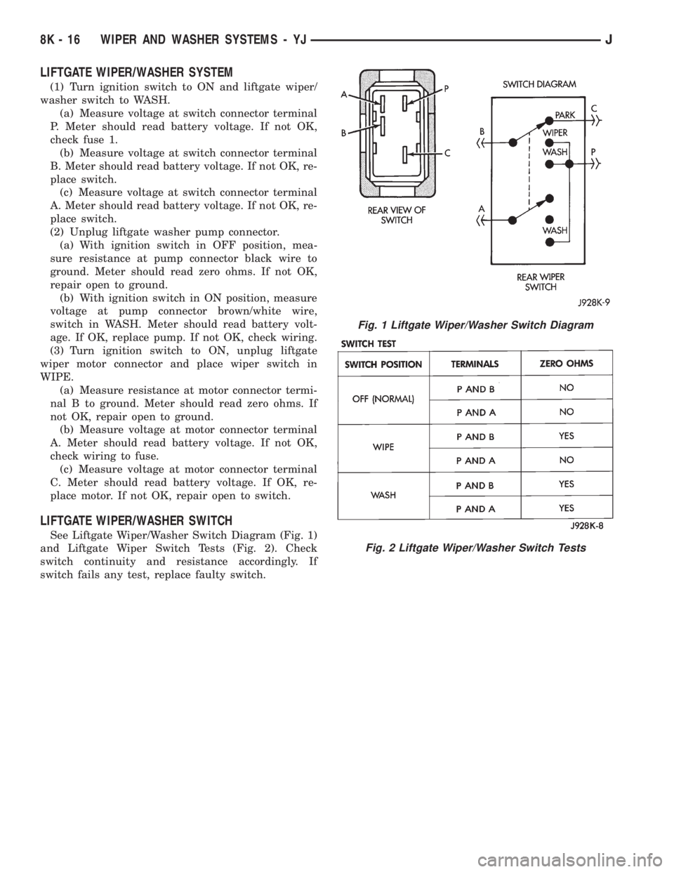
See Liftgate Wiper/Washer Switch Diagram (Fig. 1)
and Liftgate Wiper Switch Tests (Fig. 2). Check
switch continuity and resistance accordingly. If
switch fails any test, replace faulty switch.
Fig. 1 Liftgate Wiper/Washer Switch Diagram
Fig. 2 Liftgate Wiper/Washer Switch Tests
8K - 16 WIPER AND WASHER SYSTEMS - YJJ
Page 448 of 2198
LAMPS
CONTENTS
page page
BULB APPLICATIONÐXJ VEHICLES......... 18
GENERAL INFORMATION.................. 1INTERIOR LAMPS....................... 16
SERVICE PROCEDURES................... 6
GENERAL INFORMATION
Each vehicle is equipped with various lamp assem-
blies. A good ground is necessary for proper lighting
operation. Grounding is provided by the lamp socket
when it comes in contact with the metal body, or
through a separate ground wire.
When changing lamp bulbs check the socket for
corrosion. If corrosion is present, clean it with a wire
brush and coat the inside of the socket lightly with
Mopar Multi-Purpose Grease or equivalent.
DIAGNOSTIC PROCEDURESÐXJ
When a vehicle experiences problems with the
headlamp system, verify the condition of the batteryconnections, charging system, headlamp bulbs, wire
connectors, relay, high beam dimmer switch and
headlamp switch. Refer to Group 8W, Wiring Dia-
grams for component locations and circuit informa-
tion.
Always begin any diagnosis by testing all of the
fuses and circuit breakers in the system. Refer to
Group 8W, Wiring Diagrams.
JLAMPS 8L - 1
Page 466 of 2198
LAMPS
CONTENTS
page page
BULB APPLICATIONÐYJ VEHICLES......... 32
GENERAL INFORMATION................. 19INTERIOR LAMPS....................... 31
SERVICE PROCEDURES.................. 22
GENERAL INFORMATION
Each vehicle is equipped with various lamp assem-
blies. A good ground is necessary for proper lighting
operation. Grounding is provided by the lamp socket
when it comes in contact with the metal body, or
through a separate ground wire.
When changing lamp bulbs check the socket for
corrosion. If corrosion is present, clean it with a wire
brush and coat the inside of the socket lightly with
Mopar Multi-Purpose Grease or equivalent.
DIAGNOSTIC PROCEDURESÐYJ
When a vehicle experiences problems with the
headlamp system, verify the condition of the batteryconnections, charging system, headlamp bulbs, wire
connectors, relay, high beam dimmer switch and
headlamp switch. Refer to Group 8W, Wiring Dia-
grams for component locations and circuit informa-
tion.
Always begin any diagnosis by testing all of the
fuses and circuit breakers in the system. Refer to
Group 8W, Wiring Diagrams.
JLAMPSÐYJ VEHICLES 8L - 19
Page 484 of 2198
REAR WINDOW DEFOGGER
CONTENTS
page page
DIAGNOSIS............................. 1
GENERAL INFORMATION.................. 1SERVICE PROCEDURES................... 3
GENERAL INFORMATION
The electrically-heated rear window defogger is an
available option on XJ (Cherokee), and YJ (Wrangler)
models equipped with the hardtop roof option. Fol-
lowing are general descriptions of the major compo-
nents in the rear window defogger system. Refer to
Group 8W - Wiring Diagrams for complete circuit de-
scriptions and diagrams.
REAR WINDOW GLASS GRID
The heated rear window glass has two electrically-
conductive vertical bus bars and a series of horizon-
tal grid lines made of a silver-ceramic material,
which is baked on and bonded to the inside surface of
the glass. The grid lines and bus bars comprise a
parallel electrical circuit.
When the rear window defogger switch is placed in
the ON position, current is directed to the rear win-
dow grid lines through the bus bars. The grid lines
heat the rear window to clear the surface of fog or
snow. Circuit protection for the heated grid circuit is
provided by fuse 18 (XJ) or fuse 6 (YJ) in the fuse-
block module.
The grid lines and bus bars are highly resistant to
abrasion. However, it is possible for an open to occur
in an individual grid line resulting in no current flow
through the line. The grid lines can be damaged or
scraped off with sharp instruments. Care should be
taken in cleaning the glass or removing foreign ma-
terials, decals or stickers. Normal glass cleaning sol-
vents or hot water used with rags or toweling is
recommended.A repair kit is available to repair the grid lines and
bus bars, or to reinstall the heated glass pigtail
wires.
DEFOGGER SWITCH
The rear window defogger switch is mounted in the
instrument panel left of the steering column for XJ,
or right of the steering column for YJ. The switch cir-
cuit is protected by fuse 8 (XJ) or fuse 9 (YJ) in the
fuseblock module. Actuating the switch energizes the
relay and electronic timer. A light-emitting diode
(LED) in the switch (XJ), or a indicator lamp in the
switch (YJ), illuminates to indicate when the system
is turned on. The defogger switch can not be re-
paired. If faulty, the switch must be replaced.
DEFOGGER RELAY/TIMER
The defogger relay/timer is located in the relay cen-
ter on XJ models, or taped to the instrument panel
wiring harness behind the parking brake pedal in the
left cowl side area on YJ models. When the rear de-
fogger switch is actuated, the rear defogger relay is
energized. This causes current to flow through the
grid circuit for approximately 10 minutes, or until
the rear window defogger switch or ignition switch
are turned off.
DIAGNOSIS
SYSTEM TESTS
Electrically-heated rear window defogger operation
can be confirmed in the following manner:
(1) Turn the ignition switch to the ON position.
(2) Turn rear window defogger control switch ON.
(3) Monitor vehicle voltmeter. With the control
switch ON, a distinct needle deflection should be
noted.(4) The rear window defogger operation can be
checked by feeling the glass. A distinct difference in
temperature between the grid lines and adjacent
clear glass can be detected within 3 to 4 minutes of
operation.
(5) Using a DC voltmeter, contact terminal A (Fig.
1) (passenger side) with the negative lead, and termi-
JREAR WINDOW DEFOGGER 8N - 1