1995 JEEP CHEROKEE seat adjustment
[x] Cancel search: seat adjustmentPage 30 of 2198
hose unless the caliper must also be removed
for maintenance.Support the caliper with a
hanger to prevent brake fluid hose damage.
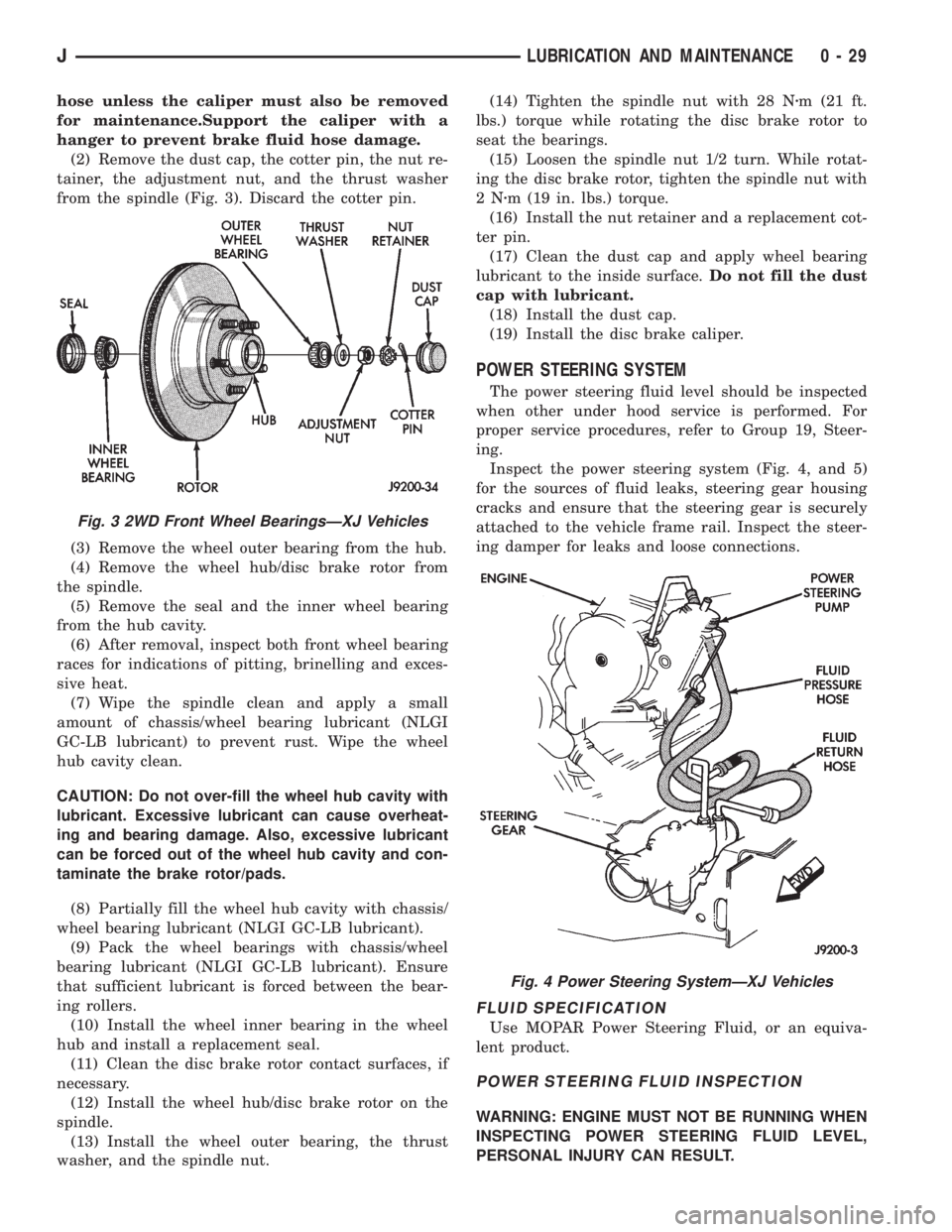
(2) Remove the dust cap, the cotter pin, the nut re-
tainer, the adjustment nut, and the thrust washer
from the spindle (Fig. 3). Discard the cotter pin.
(3) Remove the wheel outer bearing from the hub.
(4) Remove the wheel hub/disc brake rotor from
the spindle.
(5) Remove the seal and the inner wheel bearing
from the hub cavity.
(6) After removal, inspect both front wheel bearing
races for indications of pitting, brinelling and exces-
sive heat.
(7) Wipe the spindle clean and apply a small
amount of chassis/wheel bearing lubricant (NLGI
GC-LB lubricant) to prevent rust. Wipe the wheel
hub cavity clean.
CAUTION: Do not over-fill the wheel hub cavity with
lubricant. Excessive lubricant can cause overheat-
ing and bearing damage. Also, excessive lubricant
can be forced out of the wheel hub cavity and con-
taminate the brake rotor/pads.
(8) Partially fill the wheel hub cavity with chassis/
wheel bearing lubricant (NLGI GC-LB lubricant).
(9) Pack the wheel bearings with chassis/wheel
bearing lubricant (NLGI GC-LB lubricant). Ensure
that sufficient lubricant is forced between the bear-
ing rollers.
(10) Install the wheel inner bearing in the wheel
hub and install a replacement seal.
(11) Clean the disc brake rotor contact surfaces, if
necessary.
(12) Install the wheel hub/disc brake rotor on the
spindle.
(13) Install the wheel outer bearing, the thrust
washer, and the spindle nut.(14) Tighten the spindle nut with 28 Nzm (21 ft.
lbs.) torque while rotating the disc brake rotor to
seat the bearings.
(15) Loosen the spindle nut 1/2 turn. While rotat-
ing the disc brake rotor, tighten the spindle nut with
2Nzm (19 in. lbs.) torque.
(16) Install the nut retainer and a replacement cot-
ter pin.
(17) Clean the dust cap and apply wheel bearing
lubricant to the inside surface.Do not fill the dust
cap with lubricant.
(18) Install the dust cap.
(19) Install the disc brake caliper.
POWER STEERING SYSTEM
The power steering fluid level should be inspected
when other under hood service is performed. For
proper service procedures, refer to Group 19, Steer-
ing.
Inspect the power steering system (Fig. 4, and 5)
for the sources of fluid leaks, steering gear housing
cracks and ensure that the steering gear is securely
attached to the vehicle frame rail. Inspect the steer-
ing damper for leaks and loose connections.
FLUID SPECIFICATION
Use MOPAR Power Steering Fluid, or an equiva-
lent product.
POWER STEERING FLUID INSPECTION
WARNING: ENGINE MUST NOT BE RUNNING WHEN
INSPECTING POWER STEERING FLUID LEVEL,
PERSONAL INJURY CAN RESULT.
Fig. 3 2WD Front Wheel BearingsÐXJ Vehicles
Fig. 4 Power Steering SystemÐXJ Vehicles
JLUBRICATION AND MAINTENANCE 0 - 29
Page 37 of 2198
the opposite wheel. Wheels are attached to a hub/
bearings which bolts to the knuckles. The hub/bear-
ing is not serviceable and is replaced as a unit.
Steering knuckles pivot on replaceable ball studs at-
tached to the axle tube yokes.
The upper and lower suspension arms are different
lengths, with bushings at both ends. They bolt the
axle assembly to the body. The lower arms uses
shims at the body mount to allow for adjustment of
caster and drive shaft pinion angle. The suspension
arm travel is limited through the use of jounce
bumpers in compression and shocks absorbers in re-
bound.
Suspension components which use rubber bushings
should be tightened at vehicle ride height. This will
prevent premature failure of the bushing and main-
tain ride comfort. Bushings must never be lubricated.
The coil springs control ride quality and maintain
proper ride height. The coil springs mount up in the
fender shield which is part of the unitized body
bracket. A rubber isolator is located between the top
of the spring and the frame. The bottom of the spring
seats on a axle pad and is retained with a clip.
The shock absorbers dampen jounce and rebound of
the vehicle over various road conditions. The top of
the shock absorbers are bolted to the body. The bot-
tom of the shocks are bolted to the axle spring
bracket.
The stabilizer bar is used to minimize vehicle body
roll during turns. The spring steel bar helps to con-
trol the vehicle body in relationship to the suspen-
sion. The bar extends across the front underside of
the chassis and connects to the body rails. Links are
connected from the bar to the axle brackets. Stabi-
lizer bar mounts are isolated by rubber bushings.
The track bar is used to minimize front axle side-
to-side movement. The bar is attached to a frame rail
bracket with a ball stud and isolated with a bushing
at the axle bracket.
TUBE AXLE (2WD VEHICLES)
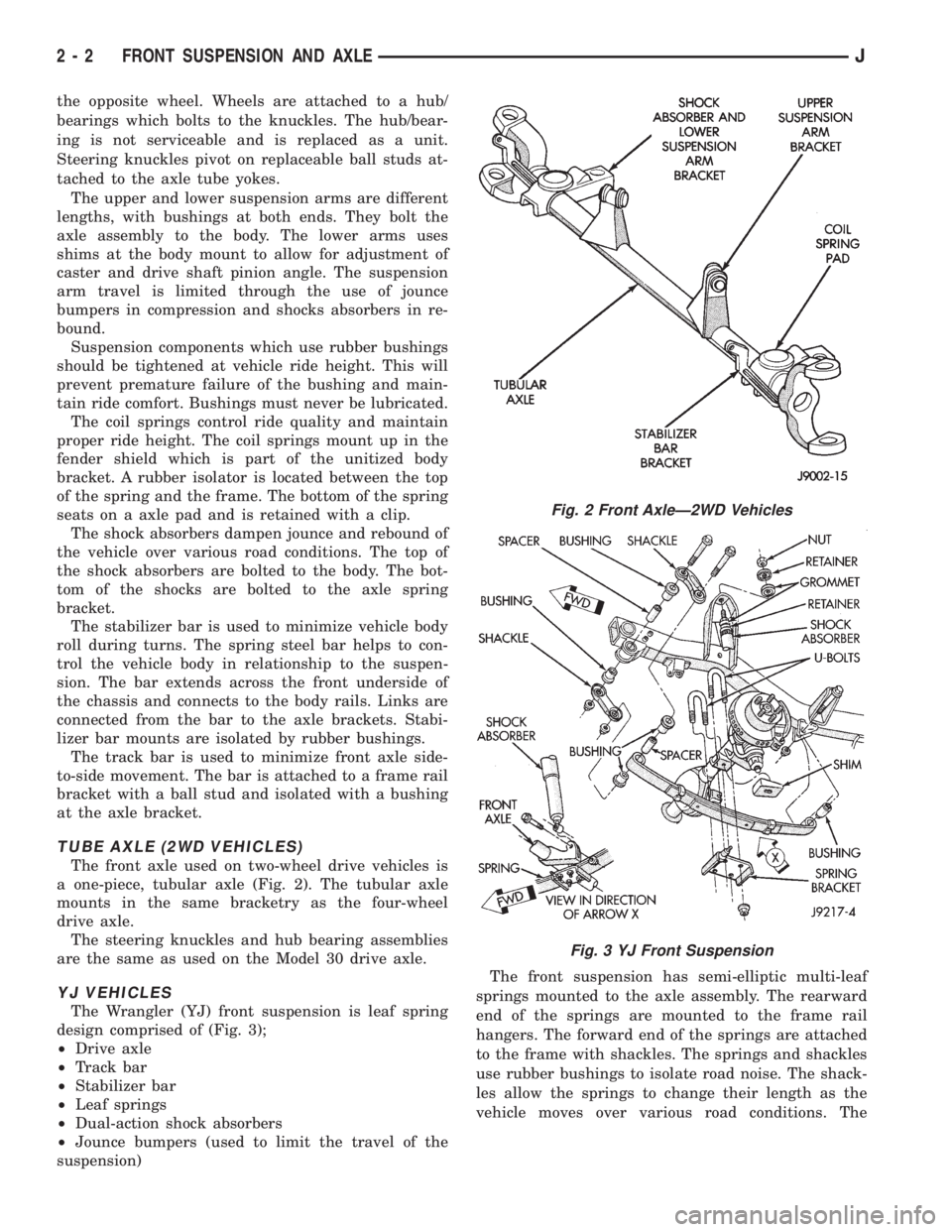
The front axle used on two-wheel drive vehicles is
a one-piece, tubular axle (Fig. 2). The tubular axle
mounts in the same bracketry as the four-wheel
drive axle.
The steering knuckles and hub bearing assemblies
are the same as used on the Model 30 drive axle.
YJ VEHICLES
The Wrangler (YJ) front suspension is leaf spring
design comprised of (Fig. 3);
²Drive axle
²Track bar
²Stabilizer bar
²Leaf springs
²Dual-action shock absorbers
²Jounce bumpers (used to limit the travel of the
suspension)The front suspension has semi-elliptic multi-leaf
springs mounted to the axle assembly. The rearward
end of the springs are mounted to the frame rail
hangers. The forward end of the springs are attached
to the frame with shackles. The springs and shackles
use rubber bushings to isolate road noise. The shack-
les allow the springs to change their length as the
vehicle moves over various road conditions. The
Fig. 2 Front AxleÐ2WD Vehicles
Fig. 3 YJ Front Suspension
2 - 2 FRONT SUSPENSION AND AXLEJ
Page 112 of 2198
BACKLASH AND CONTACT PATTERN ANALYSIS
(1) Rotate assembly several revolutions to seat
bearings. Measure backlash at three equally spaced
locations around the perimeter of the ring gear with
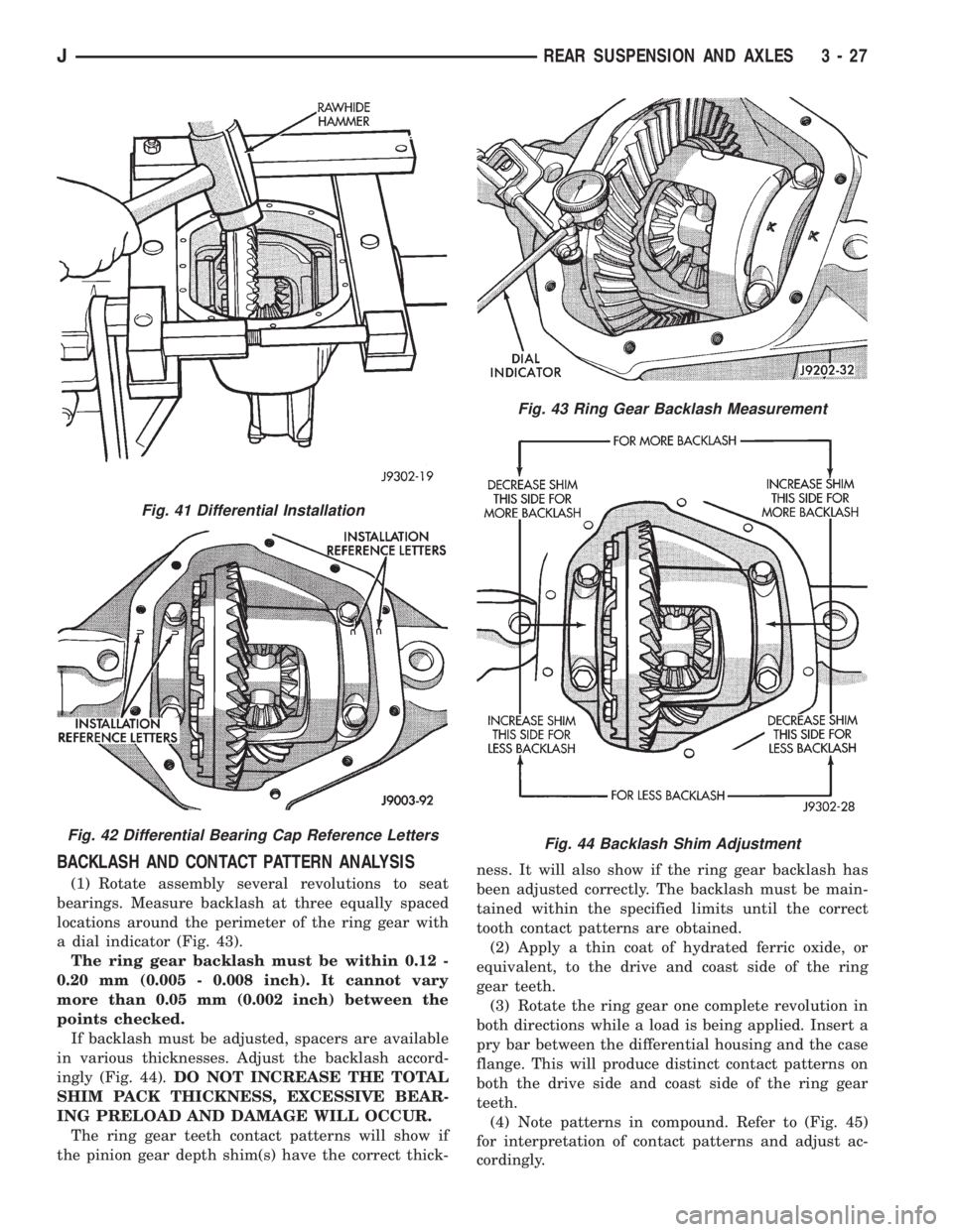
a dial indicator (Fig. 43).
The ring gear backlash must be within 0.12 -
0.20 mm (0.005 - 0.008 inch). It cannot vary
more than 0.05 mm (0.002 inch) between the
points checked.
If backlash must be adjusted, spacers are available
in various thicknesses. Adjust the backlash accord-
ingly (Fig. 44).DO NOT INCREASE THE TOTAL
SHIM PACK THICKNESS, EXCESSIVE BEAR-
ING PRELOAD AND DAMAGE WILL OCCUR.
The ring gear teeth contact patterns will show if
the pinion gear depth shim(s) have the correct thick-ness. It will also show if the ring gear backlash has
been adjusted correctly. The backlash must be main-
tained within the specified limits until the correct
tooth contact patterns are obtained.
(2) Apply a thin coat of hydrated ferric oxide, or
equivalent, to the drive and coast side of the ring
gear teeth.
(3) Rotate the ring gear one complete revolution in
both directions while a load is being applied. Insert a
pry bar between the differential housing and the case
flange. This will produce distinct contact patterns on
both the drive side and coast side of the ring gear
teeth.
(4) Note patterns in compound. Refer to (Fig. 45)
for interpretation of contact patterns and adjust ac-
cordingly.
Fig. 41 Differential Installation
Fig. 42 Differential Bearing Cap Reference Letters
Fig. 43 Ring Gear Backlash Measurement
Fig. 44 Backlash Shim Adjustment
JREAR SUSPENSION AND AXLES 3 - 27
Page 123 of 2198
(6) If removed, heat ring gear with a heat lamp or
by immersing in a hot fluid. The temperature should
not exceed 149ÉC (300ÉF).Do not use a torch to
heat the ring gear.
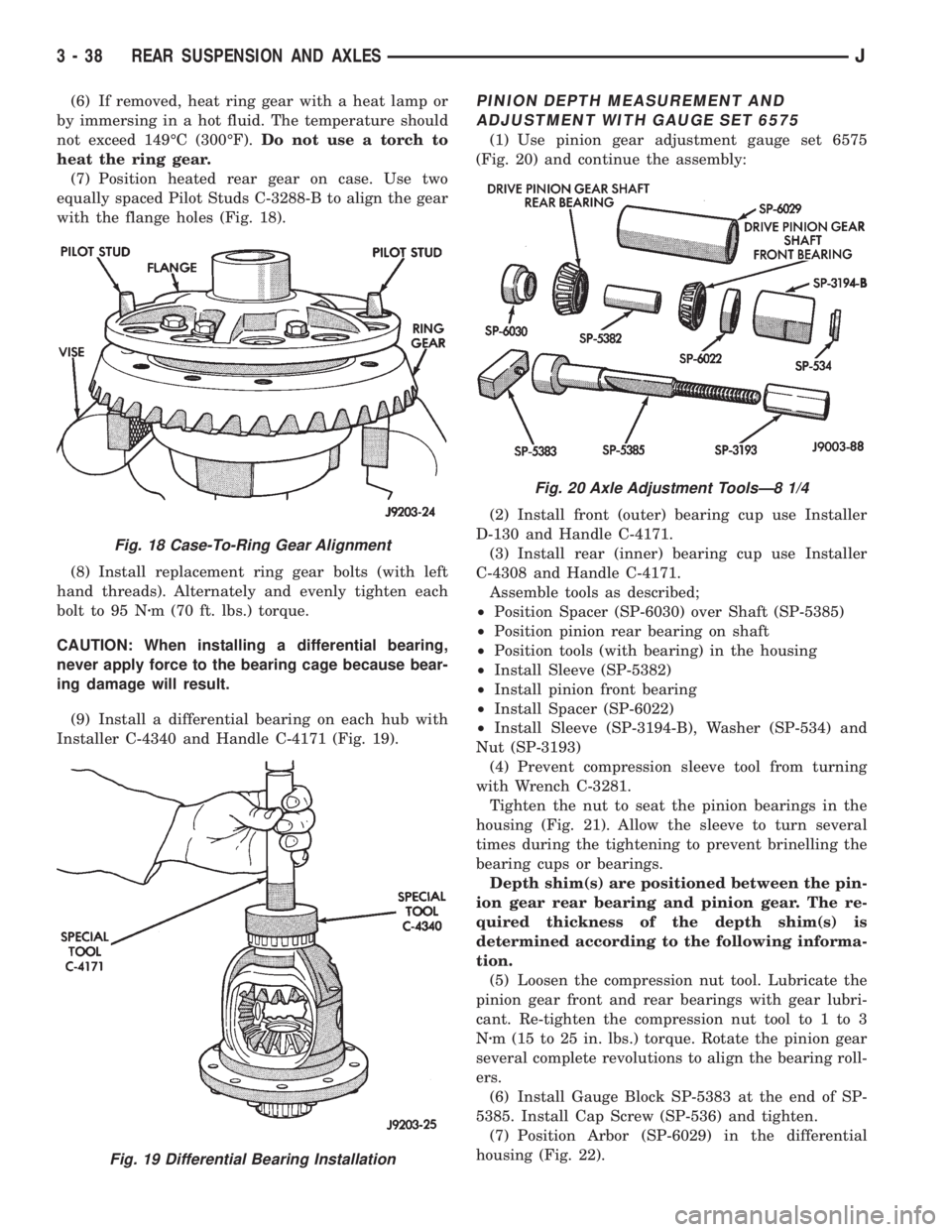
(7) Position heated rear gear on case. Use two
equally spaced Pilot Studs C-3288-B to align the gear
with the flange holes (Fig. 18).
(8) Install replacement ring gear bolts (with left
hand threads). Alternately and evenly tighten each
bolt to 95 Nzm (70 ft. lbs.) torque.
CAUTION: When installing a differential bearing,
never apply force to the bearing cage because bear-
ing damage will result.
(9) Install a differential bearing on each hub with
Installer C-4340 and Handle C-4171 (Fig. 19).PINION DEPTH MEASUREMENT AND
ADJUSTMENT WITH GAUGE SET 6575
(1) Use pinion gear adjustment gauge set 6575
(Fig. 20) and continue the assembly:
(2) Install front (outer) bearing cup use Installer
D-130 and Handle C-4171.
(3) Install rear (inner) bearing cup use Installer
C-4308 and Handle C-4171.
Assemble tools as described;
²Position Spacer (SP-6030) over Shaft (SP-5385)
²Position pinion rear bearing on shaft
²Position tools (with bearing) in the housing
²Install Sleeve (SP-5382)
²Install pinion front bearing
²Install Spacer (SP-6022)
²Install Sleeve (SP-3194-B), Washer (SP-534) and
Nut (SP-3193)
(4) Prevent compression sleeve tool from turning
with Wrench C-3281.
Tighten the nut to seat the pinion bearings in the
housing (Fig. 21). Allow the sleeve to turn several
times during the tightening to prevent brinelling the
bearing cups or bearings.
Depth shim(s) are positioned between the pin-
ion gear rear bearing and pinion gear. The re-
quired thickness of the depth shim(s) is
determined according to the following informa-
tion.
(5) Loosen the compression nut tool. Lubricate the
pinion gear front and rear bearings with gear lubri-
cant. Re-tighten the compression nut tool to 1 to 3
Nzm (15 to 25 in. lbs.) torque. Rotate the pinion gear
several complete revolutions to align the bearing roll-
ers.
(6) Install Gauge Block SP-5383 at the end of SP-
5385. Install Cap Screw (SP-536) and tighten.
(7) Position Arbor (SP-6029) in the differential
housing (Fig. 22).
Fig. 18 Case-To-Ring Gear Alignment
Fig. 19 Differential Bearing Installation
Fig. 20 Axle Adjustment ToolsÐ8 1/4
3 - 38 REAR SUSPENSION AND AXLESJ
Page 126 of 2198
CAUTION: Never loosen pinion gear nut to decrease
pinion gear bearing preload torque and never ex-
ceed specified preload torque. If preload torque is
exceeded a new collapsible spacer must be in-
stalled. The torque sequence will have to be re-
peated.
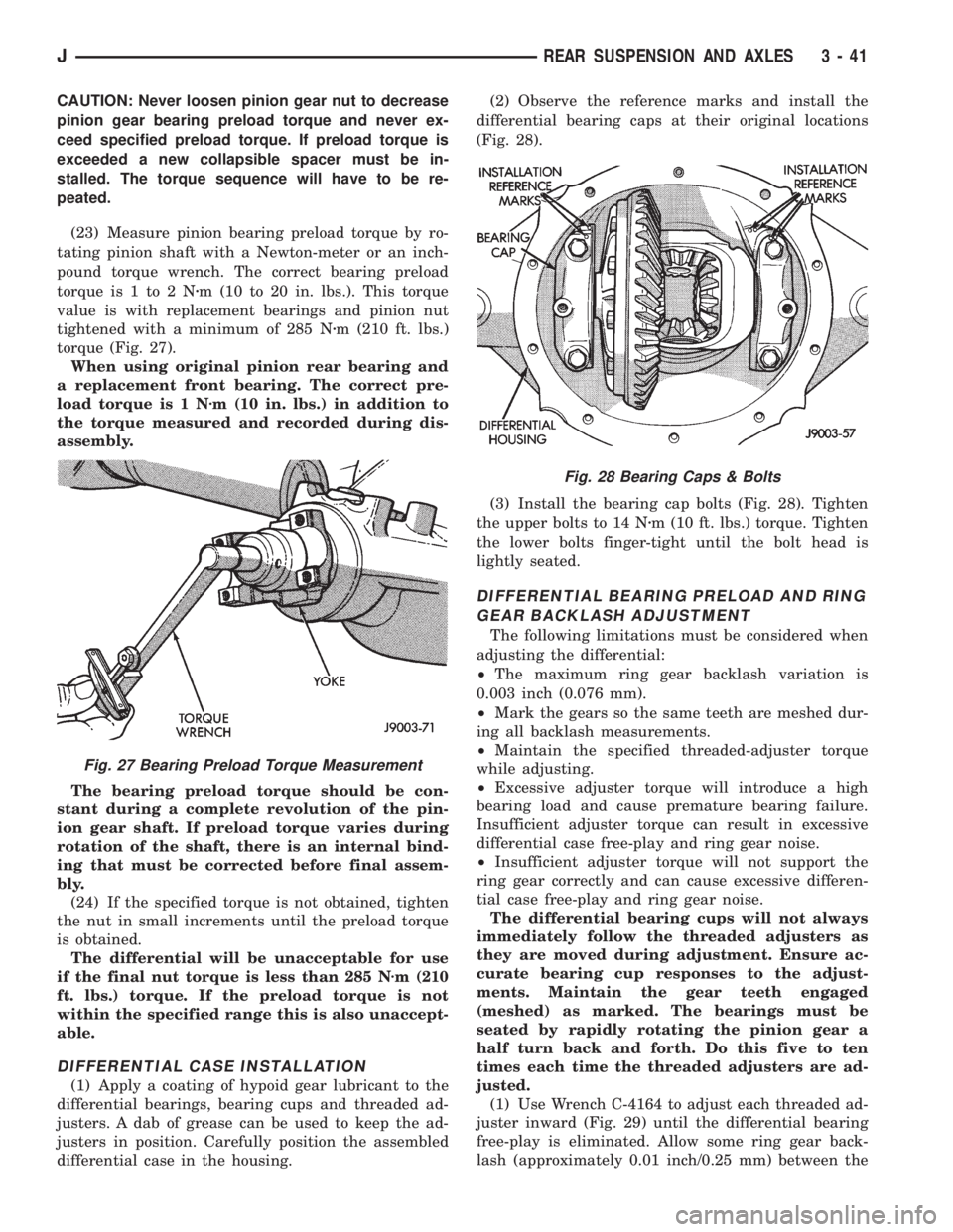
(23) Measure pinion bearing preload torque by ro-
tating pinion shaft with a Newton-meter or an inch-
pound torque wrench. The correct bearing preload
torque is 1 to 2 Nzm (10 to 20 in. lbs.). This torque
value is with replacement bearings and pinion nut
tightened with a minimum of 285 Nzm (210 ft. lbs.)
torque (Fig. 27).
When using original pinion rear bearing and
a replacement front bearing. The correct pre-
load torque is 1 Nzm (10 in. lbs.) in addition to
the torque measured and recorded during dis-
assembly.
The bearing preload torque should be con-
stant during a complete revolution of the pin-
ion gear shaft. If preload torque varies during
rotation of the shaft, there is an internal bind-
ing that must be corrected before final assem-
bly.
(24) If the specified torque is not obtained, tighten
the nut in small increments until the preload torque
is obtained.
The differential will be unacceptable for use
if the final nut torque is less than 285 Nzm (210
ft. lbs.) torque. If the preload torque is not
within the specified range this is also unaccept-
able.
DIFFERENTIAL CASE INSTALLATION
(1) Apply a coating of hypoid gear lubricant to the
differential bearings, bearing cups and threaded ad-
justers. A dab of grease can be used to keep the ad-
justers in position. Carefully position the assembled
differential case in the housing.(2) Observe the reference marks and install the
differential bearing caps at their original locations
(Fig. 28).
(3) Install the bearing cap bolts (Fig. 28). Tighten
the upper bolts to 14 Nzm (10 ft. lbs.) torque. Tighten
the lower bolts finger-tight until the bolt head is
lightly seated.
DIFFERENTIAL BEARING PRELOAD AND RING
GEAR BACKLASH ADJUSTMENT
The following limitations must be considered when
adjusting the differential:
²The maximum ring gear backlash variation is
0.003 inch (0.076 mm).
²Mark the gears so the same teeth are meshed dur-
ing all backlash measurements.
²Maintain the specified threaded-adjuster torque
while adjusting.
²Excessive adjuster torque will introduce a high
bearing load and cause premature bearing failure.
Insufficient adjuster torque can result in excessive
differential case free-play and ring gear noise.
²Insufficient adjuster torque will not support the
ring gear correctly and can cause excessive differen-
tial case free-play and ring gear noise.
The differential bearing cups will not always
immediately follow the threaded adjusters as
they are moved during adjustment. Ensure ac-
curate bearing cup responses to the adjust-
ments. Maintain the gear teeth engaged
(meshed) as marked. The bearings must be
seated by rapidly rotating the pinion gear a
half turn back and forth. Do this five to ten
times each time the threaded adjusters are ad-
justed.
(1) Use Wrench C-4164 to adjust each threaded ad-
juster inward (Fig. 29) until the differential bearing
free-play is eliminated. Allow some ring gear back-
lash (approximately 0.01 inch/0.25 mm) between the
Fig. 27 Bearing Preload Torque Measurement
Fig. 28 Bearing Caps & Bolts
JREAR SUSPENSION AND AXLES 3 - 41
Page 127 of 2198
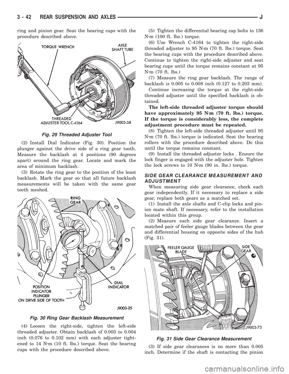
ring and pinion gear. Seat the bearing cups with the
procedure described above.
(2) Install Dial Indicator (Fig. 30). Position the
plunger against the drive side of a ring gear tooth.
Measure the backlash at 4 positions (90 degrees
apart) around the ring gear. Locate and mark the
area of minimum backlash.
(3) Rotate the ring gear to the position of the least
backlash. Mark the gear so that all future backlash
measurements will be taken with the same gear
teeth meshed.
(4) Loosen the right-side, tighten the left-side
threaded adjuster. Obtain backlash of 0.003 to 0.004
inch (0.076 to 0.102 mm) with each adjuster tight-
ened to 14 Nzm (10 ft. lbs.) torque. Seat the bearing
cups with the procedure described above.(5) Tighten the differential bearing cap bolts to 136
Nzm (100 ft. lbs.) torque.
(6) Use Wrench C-4164 to tighten the right-side
threaded adjuster to 95 Nzm (70 ft. lbs.) torque. Seat
the bearing cups with the procedure described above.
Continue to tighten the right-side adjuster and seat
bearing cups until the torque remains constant at 95
Nzm (70 ft. lbs.)
(7) Measure the ring gear backlash. The range of
backlash is 0.005 to 0.008 inch (0.127 to 0.203 mm).
Continue increasing the torque at the right-side
threaded adjuster until the specified backlash is ob-
tained.
The left-side threaded adjuster torque should
have approximately 95 Nzm (70 ft. lbs.) torque.
If the torque is considerably less, the complete
adjustment procedure must be repeated.
(8) Tighten the left-side threaded adjuster until 95
Nzm (70 ft. lbs.) torque is indicated. Seat the bearing
rollers with the procedure described above. Do this
until the torque remains constant.
(9) Install the threaded adjuster locks . Ensure the
lock finger is engaged with the adjuster hole. Tighten
the lock screws to 10 Nzm (90 in. lbs.) torque.
SIDE GEAR CLEARANCE MEASUREMENT AND
ADJUSTMENT
When measuring side gear clearance, check each
gear independently. If it necessary to replace a side
gear, replace both gears as a matched set.
(1) Install the axle shafts and C-clip locks and pin-
ion mate shaft. If necessary, refer to the installation
located within this group.
(2) Measure each side gear clearance. Insert a
matched pair of feeler gauge blades between the gear
and differential housing on opposite sides of the hub
(Fig. 31).
(3) If side gear clearances is no more than 0.005
inch. Determine if the shaft is contacting the pinion
Fig. 29 Threaded Adjuster Tool
Fig. 30 Ring Gear Backlash Measurement
Fig. 31 Side Gear Clearance Measurement
3 - 42 REAR SUSPENSION AND AXLESJ
Page 145 of 2198
produce a condition similar to grab as the tire loses
and recovers traction.
Flat-spotted tires can cause vibration and wheel
tramp and generate shudder during brake operation.
A tire with internal damage such as a severe bruise
or ply separation can cause vibration and pull. The
pull will be magnified when braking.
DIAGNOSING PARKING BRAKE MALFUNCTIONS
Adjustment Mechanism
Parking brake adjustment is controlled by a ca-
ble tensioner mechanism. The cable tensioner,
once adjusted at the factory, will not need further
attention under normal circumstances. There are
only two instances when adjustment is required.
The first is when a new tensioner, or cables have
been installed. And the second, is when the ten-
sioner and cables are disconnected for access to
other brake components.
Parking Brake Switch And Warning Light Illumination
The parking brake switch on the lever, or foot
pedal, is in circuit with the red warning light. The
switch will illuminate the red light only when the
parking brakes are applied. If the light remains on
after parking brake release, the switch or wires are
faulty, or cable tensioner adjustment is incorrect.
If the red light comes on while the vehicle is in mo-
tion and brake pedal height decreases, a fault has oc-
curred in the front or rear brake hydraulic system.
Parking Brake problem Causes
In most cases, the actual cause of an improperly
functioning parking brake (too loose/too tight/wont
hold), can be traced to a drum brake component.
The leading cause of improper parking brake
operation, is excessive clearance between the
brakeshoes and the drum surface. Excessive
clearance is a result of: lining and/or drum
wear; oversize drums; or inoperative shoe ad-
juster components.
Excessive parking brake lever travel (sometimes de-
scribed as a loose lever or too loose condition), is the re-
sult of worn brakeshoes/drums, improper brakeshoe
adjustment, or incorrectly assembled brake parts.
A ``too loose'' condition can also be caused by inop-
erative brakeshoe adjusters. If the adjusters are mis-
assembled, they will not function. In addition, since
the adjuster mechanism only works during reverse
stops, it is important that complete stops be made.
The adjuster mechanism does not operate when roll-
ing stops are made in reverse. The vehicle must be
brought to a complete halt before the adjuster lever
will turn the adjuster screw.
A condition where the parking brakes do not hold, will
most probably be due to a wheel brake component.
Items to look for when diagnosing a parking brake
problem, are:
²rear brakeshoe wear or adjuster problem
²rear brake drum wear
²brake drums machined beyond allowable diameter
(oversize)
²parking brake front cable not secured to lever
²parking brake rear cable seized
²parking brake strut reversed
²parking brake strut not seated in both shoes
²parking brake lever not seated in secondary shoe
²parking brake lever or brakeshoe bind on support
plate
²brakeshoes reversed
²adjuster screws seized
²adjuster screws reversed
²holddown or return springs misassembled or lack
tension
²wheel cylinder pistons seized
Brake drums that are machined oversize are diffi-
cult to identify without inspection. If oversize drums
are suspected, diameter of the braking surface will
have to be checked with an accurate drum gauge.
Oversize drums will cause low brake pedal and lack
of parking brake holding ability.
Improper parking brake strut and lever installation
will result in unsatisfactory parking brake operation.
Intermixing the adjuster screws will cause drag, bind
and pull along with poor parking brake operation.
Parking brake adjustment and parts replacement pro-
cedures are described in the Parking Brake section.
MASTER CYLINDER/POWER BOOSTER TEST
(1) Start engine and check booster vacuum hose
connections. Hissing noise indicates vacuum leak.
Correct any vacuum leak before proceeding.
(2) Stop engine and shift transmission into Neu-
tral.
(3) Pump brake pedal until all vacuum reserve in
booster is depleted.
(4) Press and hold brake pedal under light foot
pressure.
(a) If pedal holds firm, proceed to step (5).
(b) If pedal does not hold firm and falls away,
master cylinder is faulty due to internal leakage.
Overhaul or replace cylinder.
(5) Start engine and note pedal action.
(a) If pedal falls away slightly under light foot
pressure then holds firm, proceed to step (6).
(b) If no pedal action is discernible, or hard pedal
is noted, power booster or vacuum check valve is
faulty. Install known good check valve and repeat
steps (2) through (5).
(6) Rebuild booster vacuum reserve as follows: Re-
lease brake pedal. Increase engine speed to 1500
rpm, close throttle and immediately turn off ignition.
5 - 8 SERVICE BRAKE DIAGNOSISJ
Page 169 of 2198
BRAKELIGHT SWITCH REMOVAL
The brakelight switch is mounted in the pedal sup-
port bracket and is operated by the pedal. The switch
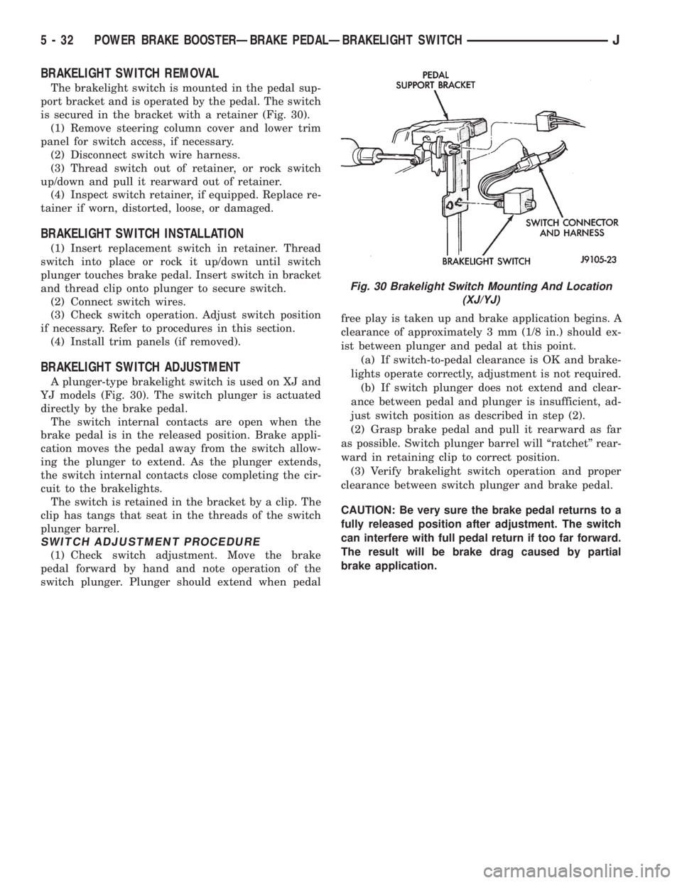
is secured in the bracket with a retainer (Fig. 30).
(1) Remove steering column cover and lower trim
panel for switch access, if necessary.
(2) Disconnect switch wire harness.
(3) Thread switch out of retainer, or rock switch
up/down and pull it rearward out of retainer.
(4) Inspect switch retainer, if equipped. Replace re-
tainer if worn, distorted, loose, or damaged.
BRAKELIGHT SWITCH INSTALLATION
(1) Insert replacement switch in retainer. Thread
switch into place or rock it up/down until switch
plunger touches brake pedal. Insert switch in bracket
and thread clip onto plunger to secure switch.
(2) Connect switch wires.
(3) Check switch operation. Adjust switch position
if necessary. Refer to procedures in this section.
(4) Install trim panels (if removed).
BRAKELIGHT SWITCH ADJUSTMENT
A plunger-type brakelight switch is used on XJ and
YJ models (Fig. 30). The switch plunger is actuated
directly by the brake pedal.
The switch internal contacts are open when the
brake pedal is in the released position. Brake appli-
cation moves the pedal away from the switch allow-
ing the plunger to extend. As the plunger extends,
the switch internal contacts close completing the cir-
cuit to the brakelights.
The switch is retained in the bracket by a clip. The
clip has tangs that seat in the threads of the switch
plunger barrel.
SWITCH ADJUSTMENT PROCEDURE
(1) Check switch adjustment. Move the brake
pedal forward by hand and note operation of the
switch plunger. Plunger should extend when pedalfree play is taken up and brake application begins. A
clearance of approximately 3 mm (1/8 in.) should ex-
ist between plunger and pedal at this point.
(a) If switch-to-pedal clearance is OK and brake-
lights operate correctly, adjustment is not required.
(b) If switch plunger does not extend and clear-
ance between pedal and plunger is insufficient, ad-
just switch position as described in step (2).
(2) Grasp brake pedal and pull it rearward as far
as possible. Switch plunger barrel will ``ratchet'' rear-
ward in retaining clip to correct position.
(3) Verify brakelight switch operation and proper
clearance between switch plunger and brake pedal.
CAUTION: Be very sure the brake pedal returns to a
fully released position after adjustment. The switch
can interfere with full pedal return if too far forward.
The result will be brake drag caused by partial
brake application.
Fig. 30 Brakelight Switch Mounting And Location
(XJ/YJ)
5 - 32 POWER BRAKE BOOSTERÐBRAKE PEDALÐBRAKELIGHT SWITCHJ