1995 JEEP CHEROKEE seat adjustment
[x] Cancel search: seat adjustmentPage 1559 of 2198
AW-4 IN-VEHICLE SERVICE
INDEX
page page
Accumulator Pistons and Springs............. 189
Adapter Housing Seal Replacement........... 191
Checking Fluid Level and Condition........... 182
Manual Valve Shaft Seal Replacement......... 187
Park Interlock Cable Adjustment............. 195
Park Rod and Pawl Service................. 190
Park/Neutral Position Switch................ 183
Refilling After Overhaul or Fluid/Filter Change . . . 182
Second Coast Brake Servo................. 190
Shift Cable Adjustment.................... 195
Speed Sensor........................... 192Speed Sensor RotorÐSpeedometer Drive Gear . . 193
Throttle Position Sensor (TPS) Service........ 193
Transmission Control Module (TCM) Service.... 183
Transmission Cooler Line Fittings............ 197
Transmission Cooler Service................ 196
Transmission Throttle Cable Adjustment........ 194
Transmission Throttle Cable Replacement...... 193
Transmission Valve Body Installation.......... 187
Transmission Valve Body Removal........... 186
Transmission Valve Body Solenoids........... 184
CHECKING FLUID LEVEL AND CONDITION
Recommended fluid for AW-4 transmissions is Mo-
par Dexron IIE/Mercon.
Mopar Dexron II can also be used but only when
Mercon fluid is not available.
CHECKING FLUID LEVEL
(1) Be sure transmission fluid is at normal operat-
ing temperature. Normal operating temperature is
reached after approximately 15 miles (25 km) of op-
eration.
(2) Position vehicle on level surface. This is impor-
tant for an accurate fluid level check.
(3) Shift transmission through all gear ranges and
back to Park.
(4) Apply parking brakes.
(5) Verify that transmission is in Park.
(6) Wipe off dipstick handle to prevent dirt from
entering fill tube. Then remove dipstick and check
fluid level and condition.
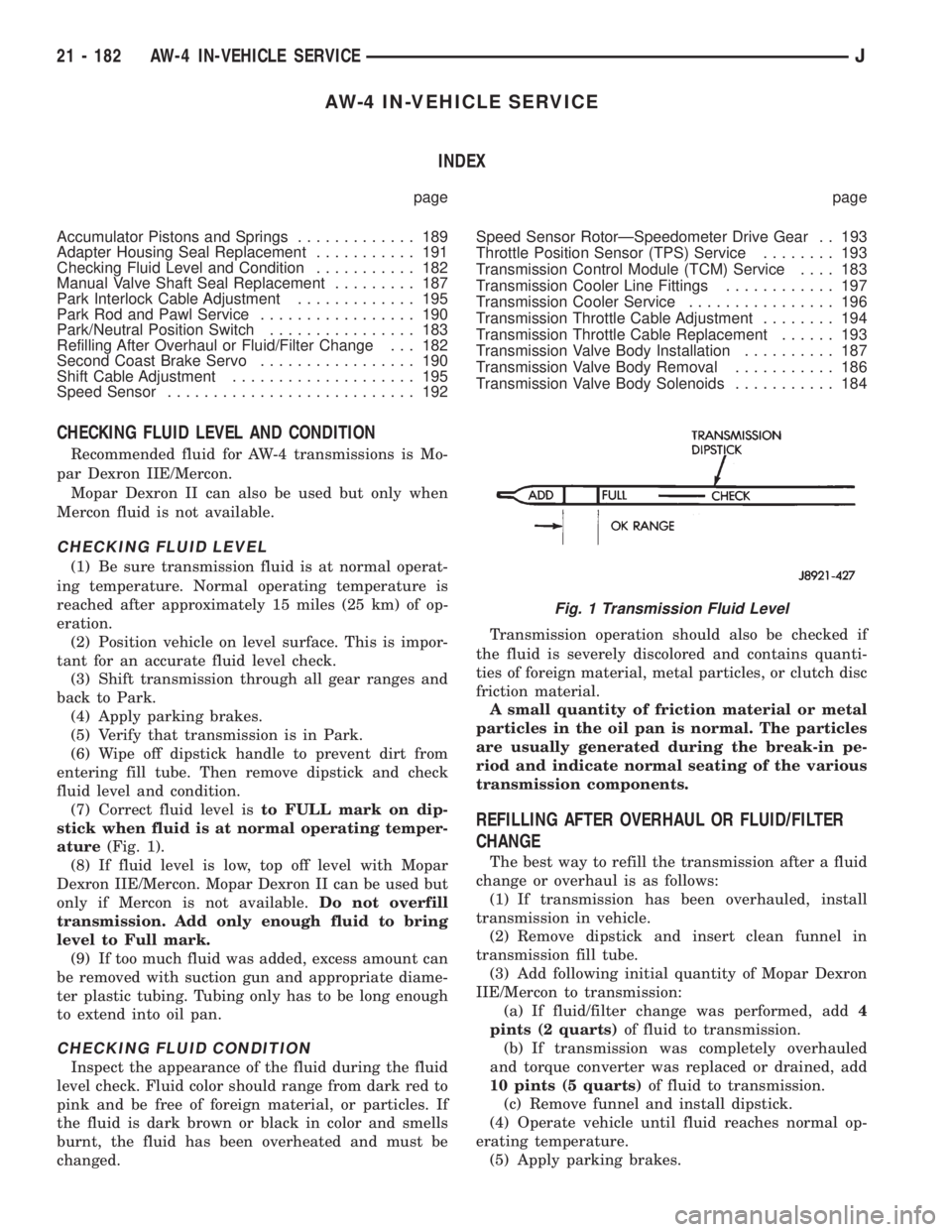
(7) Correct fluid level isto FULL mark on dip-
stick when fluid is at normal operating temper-
ature(Fig. 1).
(8) If fluid level is low, top off level with Mopar
Dexron IIE/Mercon. Mopar Dexron II can be used but
only if Mercon is not available.Do not overfill
transmission. Add only enough fluid to bring
level to Full mark.
(9) If too much fluid was added, excess amount can
be removed with suction gun and appropriate diame-
ter plastic tubing. Tubing only has to be long enough
to extend into oil pan.
CHECKING FLUID CONDITION
Inspect the appearance of the fluid during the fluid
level check. Fluid color should range from dark red to
pink and be free of foreign material, or particles. If
the fluid is dark brown or black in color and smells
burnt, the fluid has been overheated and must be
changed.Transmission operation should also be checked if
the fluid is severely discolored and contains quanti-
ties of foreign material, metal particles, or clutch disc
friction material.
A small quantity of friction material or metal
particles in the oil pan is normal. The particles
are usually generated during the break-in pe-
riod and indicate normal seating of the various
transmission components.
REFILLING AFTER OVERHAUL OR FLUID/FILTER
CHANGE
The best way to refill the transmission after a fluid
change or overhaul is as follows:
(1) If transmission has been overhauled, install
transmission in vehicle.
(2) Remove dipstick and insert clean funnel in
transmission fill tube.
(3) Add following initial quantity of Mopar Dexron
IIE/Mercon to transmission:
(a) If fluid/filter change was performed, add4
pints (2 quarts)of fluid to transmission.
(b) If transmission was completely overhauled
and torque converter was replaced or drained, add
10 pints (5 quarts)of fluid to transmission.
(c) Remove funnel and install dipstick.
(4) Operate vehicle until fluid reaches normal op-
erating temperature.
(5) Apply parking brakes.
Fig. 1 Transmission Fluid Level
21 - 182 AW-4 IN-VEHICLE SERVICEJ
Page 1560 of 2198
(6) Let engine run at normal curb idle speed, apply
service brakes. Then shift transmission through all
gear ranges and back to PARK (leave engine run-
ning).
(7) Remove dipstick and check fluid level. Add only
enough fluid to bring level to Full mark on dipstick.
Do not overfill.If too much fluid is added, excess
amount can be removed with suction gun and
plastic tubing. Tubing only has to be long
enough to extend into oil pan.
(8) When fluid level is correct, shut engine off, re-
lease park brake, remove funnel, and reseat dipstick
in fill tube.
TRANSMISSION CONTROL MODULE (TCM)
SERVICE
Use the DRB scan tool to diagnose transmission
control module function whenever a fault is sus-
pected. Replace the module only when the scan tool
indicates the module is actually faulty.
TRANSMISSION CONTROL MODULE
REPLACEMENT
The transmission control module is mounted under
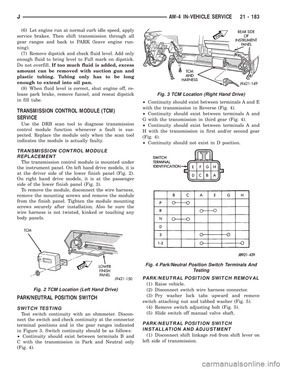
the instrument panel. On left hand drive models, it is
at the driver side of the lower finish panel (Fig. 2).
On right hand drive models, it is at the passenger
side of the lower finish panel (Fig. 3).
To remove the module, disconnect the wire harness,
remove the mounting screws and remove the module
from the finish panel. Tighten the module mounting
screws securely after installation. Also be sure the
wire harness is not twisted, kinked or touching any
body panels.
PARK/NEUTRAL POSITION SWITCH
SWITCH TESTING
Test switch continuity with an ohmmeter. Discon-
nect the switch and check continuity at the connector
terminal positions and in the gear ranges indicated
in Figure 3. Switch continuity should be as follows:
²Continuity should exist between terminals B and
C with the transmission in Park and Neutral only
(Fig. 4).²Continuity should exist between terminals A and E
with the transmission in Reverse (Fig. 4).
²Continuity should exist between terminals A and
G with the transmission in third gear (Fig. 4).
²Continuity should exist between terminals A and
H with the transmission in first and/or second gear
(Fig. 4).
²Continuity should not exist in D position.
PARK/NEUTRAL POSITION SWITCH REMOVAL
(1) Raise vehicle.
(2) Disconnect switch wire harness connector.
(3) Pry washer lock tabs upward and remove
switch attaching nut and tabbed washer (Fig. 5).
(4) Remove switch adjusting bolt (Fig. 5).
(5) Slide switch off manual valve shaft.
PARK/NEUTRAL POSITION SWITCH
INSTALLATION AND ADJUSTMENT
(1) Disconnect shift linkage rod from shift lever on
left side of transmission.
Fig. 2 TCM Location (Left Hand Drive)
Fig. 3 TCM Location (Right Hand Drive)
Fig. 4 Park/Neutral Position Switch Terminals And
Testing
JAW-4 IN-VEHICLE SERVICE 21 - 183
Page 1684 of 2198
NP242 TRANSFER CASE
INDEX
page page
General Information....................... 307
Operating Ranges........................ 307
Overhaul Cleaning and Inspection............ 318
Recommended Lubricant/Capacity/Fill Level..... 307
Shift Lever Installation (XJ)................. 309
Shift Lever Removal (XJ)................... 309
Shift Linkage Adjustment................... 309
Shift Mechanism......................... 307Speedometer Service..................... 309
Transfer Case Assembly................... 319
Transfer Case Changes.................... 307
Transfer Case Disassembly and Overhaul...... 310
Transfer Case Identification................. 307
Transfer Case Installation.................. 309
Transfer Case Removal.................... 309
GENERAL INFORMATION
The NP242 is a full and part-time transfer case
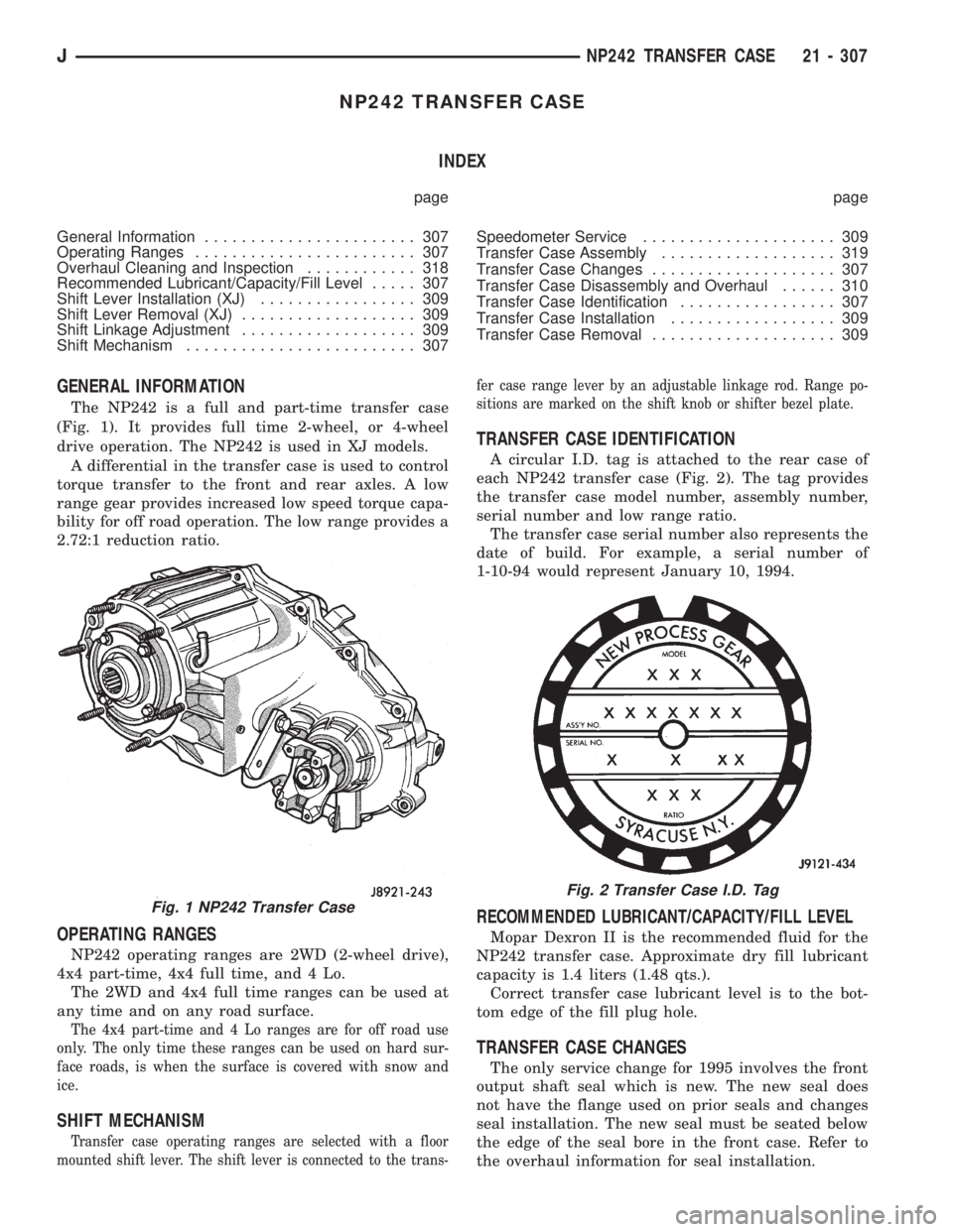
(Fig. 1). It provides full time 2-wheel, or 4-wheel
drive operation. The NP242 is used in XJ models.
A differential in the transfer case is used to control
torque transfer to the front and rear axles. A low
range gear provides increased low speed torque capa-
bility for off road operation. The low range provides a
2.72:1 reduction ratio.
OPERATING RANGES
NP242 operating ranges are 2WD (2-wheel drive),
4x4 part-time, 4x4 full time, and 4 Lo.
The 2WD and 4x4 full time ranges can be used at
any time and on any road surface.
The 4x4 part-time and 4 Lo ranges are for off road use
only. The only time these ranges can be used on hard sur-
face roads, is when the surface is covered with snow and
ice.
SHIFT MECHANISM
Transfer case operating ranges are selected with a floor
mounted shift lever. The shift lever is connected to the trans-fer case range lever by an adjustable linkage rod. Range po-
sitions are marked on the shift knob or shifter bezel plate.
TRANSFER CASE IDENTIFICATION
A circular I.D. tag is attached to the rear case of
each NP242 transfer case (Fig. 2). The tag provides
the transfer case model number, assembly number,
serial number and low range ratio.
The transfer case serial number also represents the
date of build. For example, a serial number of
1-10-94 would represent January 10, 1994.
RECOMMENDED LUBRICANT/CAPACITY/FILL LEVEL
Mopar Dexron II is the recommended fluid for the
NP242 transfer case. Approximate dry fill lubricant
capacity is 1.4 liters (1.48 qts.).
Correct transfer case lubricant level is to the bot-
tom edge of the fill plug hole.
TRANSFER CASE CHANGES
The only service change for 1995 involves the front
output shaft seal which is new. The new seal does
not have the flange used on prior seals and changes
seal installation. The new seal must be seated below
the edge of the seal bore in the front case. Refer to
the overhaul information for seal installation.
Fig. 1 NP242 Transfer Case
Fig. 2 Transfer Case I.D. Tag
JNP242 TRANSFER CASE 21 - 307
Page 1731 of 2198
VEHICLE VIBRATION
Vehicle vibration can be caused by:
²Tire/wheel unbalance or excessive runout
²Defective tires with extreme tread wear
²Nylon overlay flat spots (performance tires only)
²Incorrect wheel bearing adjustment (if applicable)
²Loose or worn suspension/steering components
²Certain tire tread patterns
²Incorrect drive shaft angles or excessive drive
shaft/yoke runout
²Defective or worn U-joints
²Excessive brake rotor or drum runout
²Loose engine or transmission supports/mounts
²And by engine operated accessories
Refer to the appropriate Groups in this man-
ual for additional information.
VIBRATION TYPES
There are two types of vehicle vibration:
²Mechanical
²Audible.
Mechanical vehicle vibration can be felt through
the seats, floor pan and/or steering wheel.
Audible vehicle vibration is heard above normal
background noise. The sound can be a droning or
drumming noise.
Vibrations are sensitive to change in engine torque,
vehicle speed or engine speed.
ENGINE TORQUE SENSITIVE VIBRATION
This vibration can be increased or decreased by:
²Accelerating
²Decelerating
²Coasting
²Maintaining a constant vehicle speed
VEHICLE SPEED SENSITIVE VIBRATION
This vibration condition always occurs at the same
vehicle speed regardless of the engine torque or en-
gine speed.
ENGINE SPEED (RPM) SENSITIVE VIBRATION
This vibration occurs at varying engine speeds. It
can be isolated by increasing or decreasing the en-
gine speed with the transmission in NEUTRAL posi-
tion.
VIBRATION DIAGNOSIS
A vibration diagnosis should always begin with a
10 mile (16 km) trip (to warm the vehicle and tires).
Then a road test to identify the vibration. Corrective
action should not be attempted until the vibration
type has been identified via a road test.
During the road test, drive the vehicle on a smooth
surface. If vibration exists, note and record the fol-
lowing information:²Identify the vehicle speed range when the vibra-
tion occurs
²Identify the type of vibration
²Identify the vibration sensitivity
²Determine if the vibration is affected by changes
in vehicle speed, engine speed and engine torque.
When the vibration has been identified, refer to the
Vibration Diagnosis chart for causes. Consider cor-
recting only those causes coded in the chart that are
related to the vibration condition.
Refer to the following cause codes and descriptions
for explanations when referring to the chart.
TRRÐTire and Wheel Radial Runout:Vehicle
speed sensitive, mechanical vibration. The runout
will not cause vibration below 20 mph (32 km/h).
WHÐWheel Hop:Vehicle speed sensitive, me-
chanical vibration. The wheel hop generates rapid
up-down movement in the steering wheel. The vibra-
tion is most noticeable in the 20 - 40 mph (32 - 64
km/h) range. The wheel hop will not cause vibration
below 20 mph (32 km/h). Wheel hop is caused by a
tire/wheel that has a radial runout of more than
0.045 of-an-inch (1.14 mm). If wheel runout is accept-
able and combined runout cannot be reduced by re-
positioning the tire on wheel, replace tire.
TBÐTire/Wheel Balance:Vehicle speed sensitive,
mechanical vibration. Static tire/wheel unbalance
will not cause vibration below 30 mph (46 km/h). Dy-
namic tire/wheel unbalance will not cause vibration
below 40 mph (64 km/h).
TLRÐTire/Wheel Lateral runout:Vehicle speed
sensitive, mechanical vibration. The runout will not
cause vibration below 50 - 55 mph (80 - 88 km/h). Ex-
cessive lateral runout will also cause front-end
shimmy.
TWÐTire Wear:Vehicle speed sensitive, audible
vibration. Abnormal tire wear causes small vibration
in the 30 - 55 mph (88 km/h) range. This will pro-
duce a whine noise at high speed. The whine will
change to a growl noise when the speed is reduced.
WÐTire Waddle:Vehicle speed sensitive, mechan-
ical vibration. Irregular tire uniformity can cause
side-to-side motion during speeds up to 15 mph (24
km/h). If the motion is excessive, identify the defec-
tive tire and replace it.
UAJÐUniversal Joint (Drive Shaft) Angles:
Torque/vehicle speed sensitive, mechanical/audible vi-
bration. Incorrect drive shaft angles cause mechani-
cal vibration below 20 mph (32 km/h) and in the 70
mph (112 km/h) range. The incorrect angles can also
produce an audible vibration in the 20 - 50 mph (32 -
80 km/h) range. Caster adjustment could be required
to correct the angles.
UJÐUniversal Joints:Engine torque/vehicle
speed sensitive, mechanical/audible vibration. If the
22 - 10 WHEELS AND TIRESJ
Page 1770 of 2198
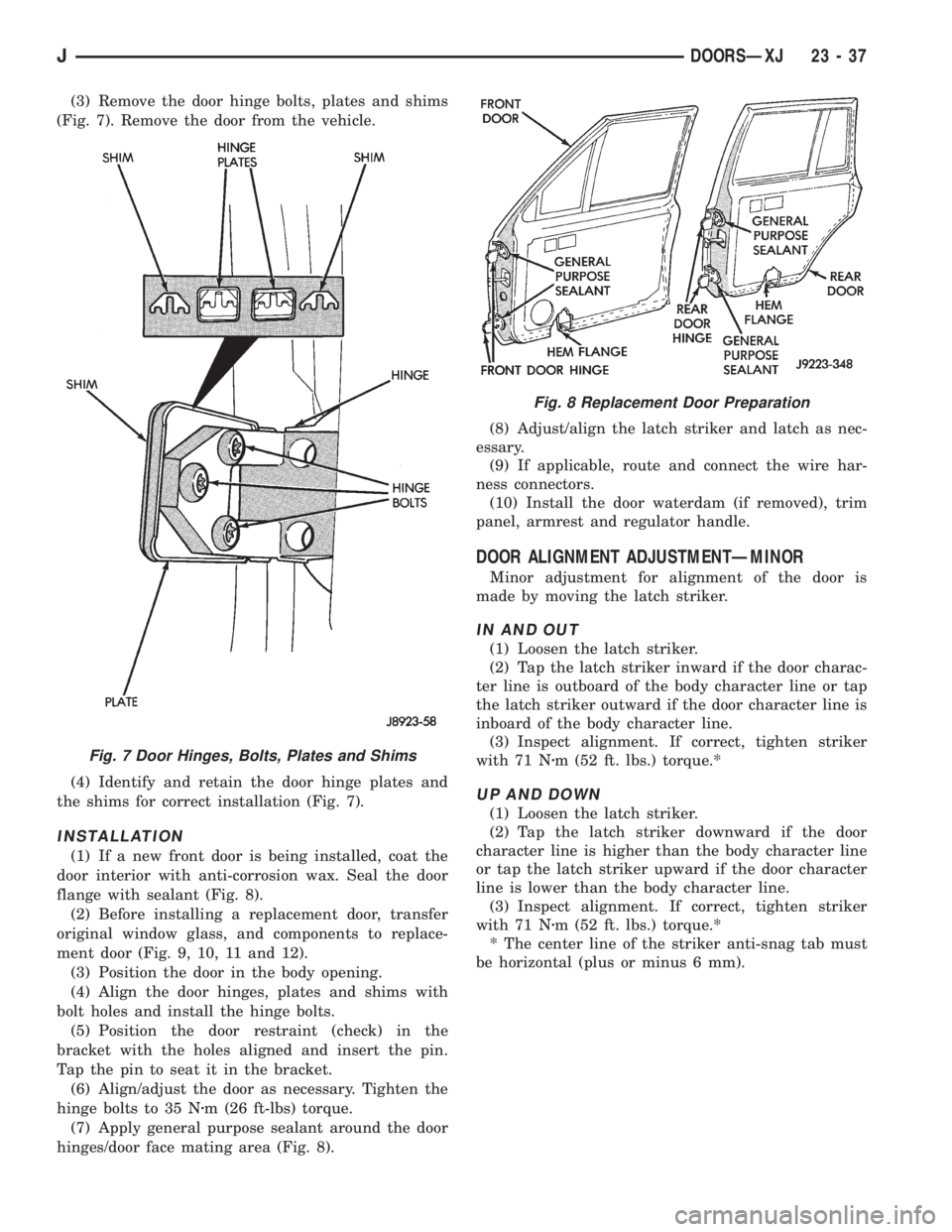
(3) Remove the door hinge bolts, plates and shims
(Fig. 7). Remove the door from the vehicle.
(4) Identify and retain the door hinge plates and
the shims for correct installation (Fig. 7).
INSTALLATION
(1) If a new front door is being installed, coat the
door interior with anti-corrosion wax. Seal the door
flange with sealant (Fig. 8).
(2) Before installing a replacement door, transfer
original window glass, and components to replace-
ment door (Fig. 9, 10, 11 and 12).
(3) Position the door in the body opening.
(4) Align the door hinges, plates and shims with
bolt holes and install the hinge bolts.
(5) Position the door restraint (check) in the
bracket with the holes aligned and insert the pin.
Tap the pin to seat it in the bracket.
(6) Align/adjust the door as necessary. Tighten the
hinge bolts to 35 Nzm (26 ft-lbs) torque.
(7) Apply general purpose sealant around the door
hinges/door face mating area (Fig. 8).(8) Adjust/align the latch striker and latch as nec-
essary.
(9) If applicable, route and connect the wire har-
ness connectors.
(10) Install the door waterdam (if removed), trim
panel, armrest and regulator handle.
DOOR ALIGNMENT ADJUSTMENTÐMINOR
Minor adjustment for alignment of the door is
made by moving the latch striker.
IN AND OUT
(1) Loosen the latch striker.
(2) Tap the latch striker inward if the door charac-
ter line is outboard of the body character line or tap
the latch striker outward if the door character line is
inboard of the body character line.
(3) Inspect alignment. If correct, tighten striker
with 71 Nzm (52 ft. lbs.) torque.*
UP AND DOWN
(1) Loosen the latch striker.
(2) Tap the latch striker downward if the door
character line is higher than the body character line
or tap the latch striker upward if the door character
line is lower than the body character line.
(3) Inspect alignment. If correct, tighten striker
with 71 Nzm (52 ft. lbs.) torque.*
* The center line of the striker anti-snag tab must
be horizontal (plus or minus 6 mm).
Fig. 7 Door Hinges, Bolts, Plates and Shims
Fig. 8 Replacement Door Preparation
JDOORSÐXJ 23 - 37
Page 1797 of 2198
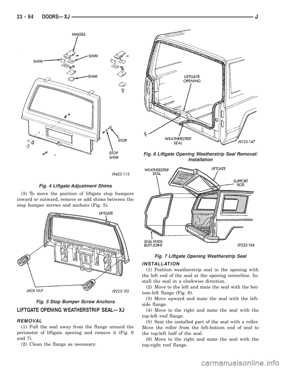
(3) To move the position of liftgate stop bumpers
inward or outward, remove or add shims between the
stop bumper screws and anchors (Fig. 5).
LIFTGATE OPENING WEATHERSTRIP SEALÐXJ
REMOVAL
(1) Pull the seal away from the flange around the
perimeter of liftgate opening and remove it (Fig. 6
and 7).
(2) Clean the flange as necessary.
INSTALLATION
(1) Position weatherstrip seal in the opening with
the left end of the seal at the opening centerline. In-
stall the seal in a clockwise direction.
(2) Move to the left and mate the seal with the bot-
tom-left flange (Fig. 6).
(3) Move upward and mate the seal with the left-
side flange.
(4) Move to the right and mate the seal with the
top-left roof flange.
(5) Seat the installed part of the seal with a roller.
Move the roller from the left-bottom end of seal to
the top-left half of the seal.
(6) Move to the right and mate the seal with the
top-right roof flange.
Fig. 4 Liftgate Adjustment Shims
Fig. 5 Stop Bumper Screw Anchors
Fig. 6 Liftgate Opening Weatherstrip Seal Removal/
Installation
Fig. 7 Liftgate Opening Weatherstrip Seal
23 - 64 DOORSÐXJJ
Page 1854 of 2198
(3) Position the replacement nameplate on the
panel and apply inward force to seat it.
FUEL FILLER PROTECTOR/NOZZLEÐYJ
REMOVAL
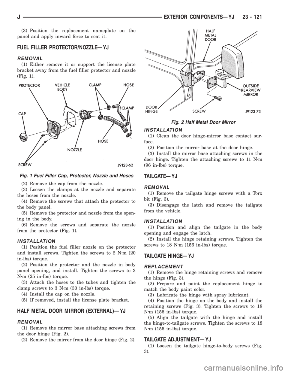
(1) Either remove it or support the license plate
bracket away from the fuel filler protector and nozzle
(Fig. 1).
(2) Remove the cap from the nozzle.
(3) Loosen the clamps at the nozzle and separate
the hoses from the nozzle.
(4) Remove the screws that attach the protector to
the body panel.
(5) Remove the protector and nozzle from the open-
ing in the body.
(6) Remove the screws and separate the nozzle
from the protector (Fig. 1).
INSTALLATION
(1) Position the fuel filler nozzle on the protector
and install screws. Tighten the screws to 2 Nzm (20
in-lbs) torque.
(2) Position the protector and the nozzle in body
panel opening, and install. Tighten the screws to 3
Nzm (25 in-lbs) torque.
(3) Attach the hoses to the tubes and tighten the
clamp screws to 3 Nzm (30 in-lbs) torque.
(4) Install the cap on the nozzle.
(5) If removed, install the license plate bracket.
HALF METAL DOOR MIRROR (EXTERNAL)ÐYJ
REMOVAL
(1) Remove the mirror base attaching screws from
the door hinge (Fig. 2).
(2) Remove the mirror from the door hinge (Fig. 2).
INSTALLATION
(1) Clean the door hinge-mirror base contact sur-
face.
(2) Position the mirror base at the door hinge.
(3) Install the mirror base attaching screws in the
door hinge. Tighten the attaching screws to 11 Nzm
(96 in-lbs) torque.
TAILGATEÐYJ
REMOVAL
(1) Remove the tailgate hinge screws with a Torx
bit (Fig. 3).
(3) Disengage the latch and remove the tailgate
from the vehicle.
INSTALLATION
(1) Position and align the tailgate in the body
opening and engage the latch.
(2) Install the hinge retaining screws. Tighten the
screws to 18 Nzm (156 in-lbs) torque.
TAILGATE HINGEÐYJ
REPLACEMENT
(1) Remove the hinge retaining screws and remove
the hinge (Fig. 3).
(2) Prepare and paint the replacement hinge to
match the body paint color.
(3) Lubricate the hinge with spray lubricant.
(4) Position the hinge on the body and install the
retaining screws (Fig. 3). Tighten the screws to 18
Nzm (156 in-lbs) torque.
(5) Align the tailgate with the hinge and install
the hinge-to-tailgate screws. Tighten the screws to 18
Nzm (156 in-lbs) torque.
TAILGATE ADJUSTMENTÐYJ
(1) Loosen the tailgate hinge-to-body screws (Fig.
3).
Fig. 1 Fuel Filler Cap, Protector, Nozzle and Hoses
Fig. 2 Half Metal Door Mirror
JEXTERIOR COMPONENTSÐYJ 23 - 121
Page 1886 of 2198
REMOVAL
(1) Remove the hinge-to-glove box housing retain-
ing screws.
(2) Remove the door and the hinge from the glove
box housing.
(3) If necessary, remove the retaining screws and
the hinge from the glove box door.
INSTALLATION
(1) If removed, install the hinge on the glove box
door with screws. Tighten the screws securely.
(2) Position the glove box door and hinge on the
glove box housing.
(3) Install the hinge-to-glove box housing screws
and adjust the door for proper fit within the opening.
Tighten the screws securely.
DOOR LATCH STRIKER ADJUSTMENT
The glove box door lock cylinder latch striker is at-
tached to the glove box housing opening with screws.
The striker can be moved in or out for adjustment.
SEATSÐYJ
Bucket-type front seats are standard on YJ vehi-
cles. The rear passenger seat is a forward pivoting/
folding, bench-type seat.
BUCKET SEATSÐYJ
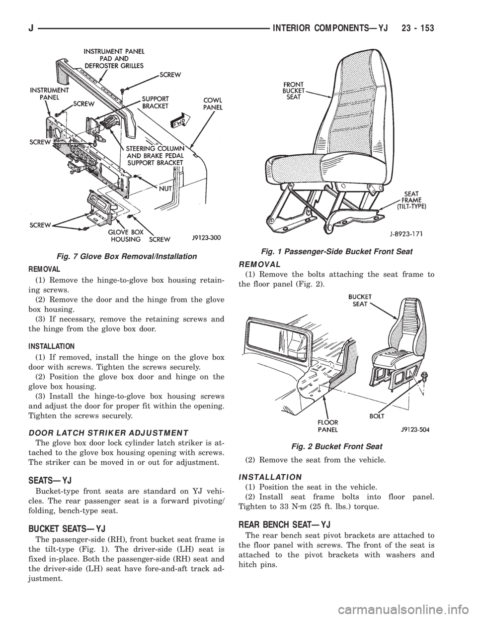
The passenger-side (RH), front bucket seat frame is
the tilt-type (Fig. 1). The driver-side (LH) seat is
fixed in-place. Both the passenger-side (RH) seat and
the driver-side (LH) seat have fore-and-aft track ad-
justment.
REMOVAL
(1) Remove the bolts attaching the seat frame to
the floor panel (Fig. 2).
(2) Remove the seat from the vehicle.
INSTALLATION
(1) Position the seat in the vehicle.
(2) Install seat frame bolts into floor panel.
Tighten to 33 Nzm (25 ft. lbs.) torque.
REAR BENCH SEATÐYJ
The rear bench seat pivot brackets are attached to
the floor panel with screws. The front of the seat is
attached to the pivot brackets with washers and
hitch pins.
Fig. 7 Glove Box Removal/InstallationFig. 1 Passenger-Side Bucket Front Seat
Fig. 2 Bucket Front Seat
JINTERIOR COMPONENTSÐYJ 23 - 153