1995 JEEP CHEROKEE instrument panel
[x] Cancel search: instrument panelPage 2 of 2198
LUBRICATION AND MAINTENANCE
CONTENTS
page page
CHASSIS AND BODY COMPONENTS........ 28
DRIVETRAIN........................... 22
ENGINE MAINTENANCE................... 15GENERAL INFORMATION.................. 1
JUMP STARTING, TOWING AND HOISTING.... 9
MAINTENANCE SCHEDULES................ 4
GENERAL INFORMATION
INDEX
page page
Classification of Lubricants................... 2
Components Requiring No Lubrication........... 2
Fluid Capacities........................... 3
Fuel Requirements......................... 1International Symbols....................... 1
Introduction.............................. 1
Lubrication and Replacement Parts
Recommendation......................... 2
INTRODUCTION
Lubrication and maintenance is divided into re-
quired and recommended service tasks. The required
service tasks must be completed to verify the emis-
sion controls function correctly. The recommended
service tasks should be completed to maintain safety
and durability.
This information will assist the service personnel
in providing maximum protection for each owner's
vehicle.
Conditions can vary with individual driving habits.
It is necessary to schedule maintenance as a time in-
terval as well as a distance interval.
It is the owner's responsibility to determine the ap-
plicable driving condition. Also to have the vehicle
serviced according to the maintenance schedule, and
to pay for the necessary parts and labor.
Additional maintenance and lubrication informa-
tion is listed in the Owner's Manual.
INTERNATIONAL SYMBOLS
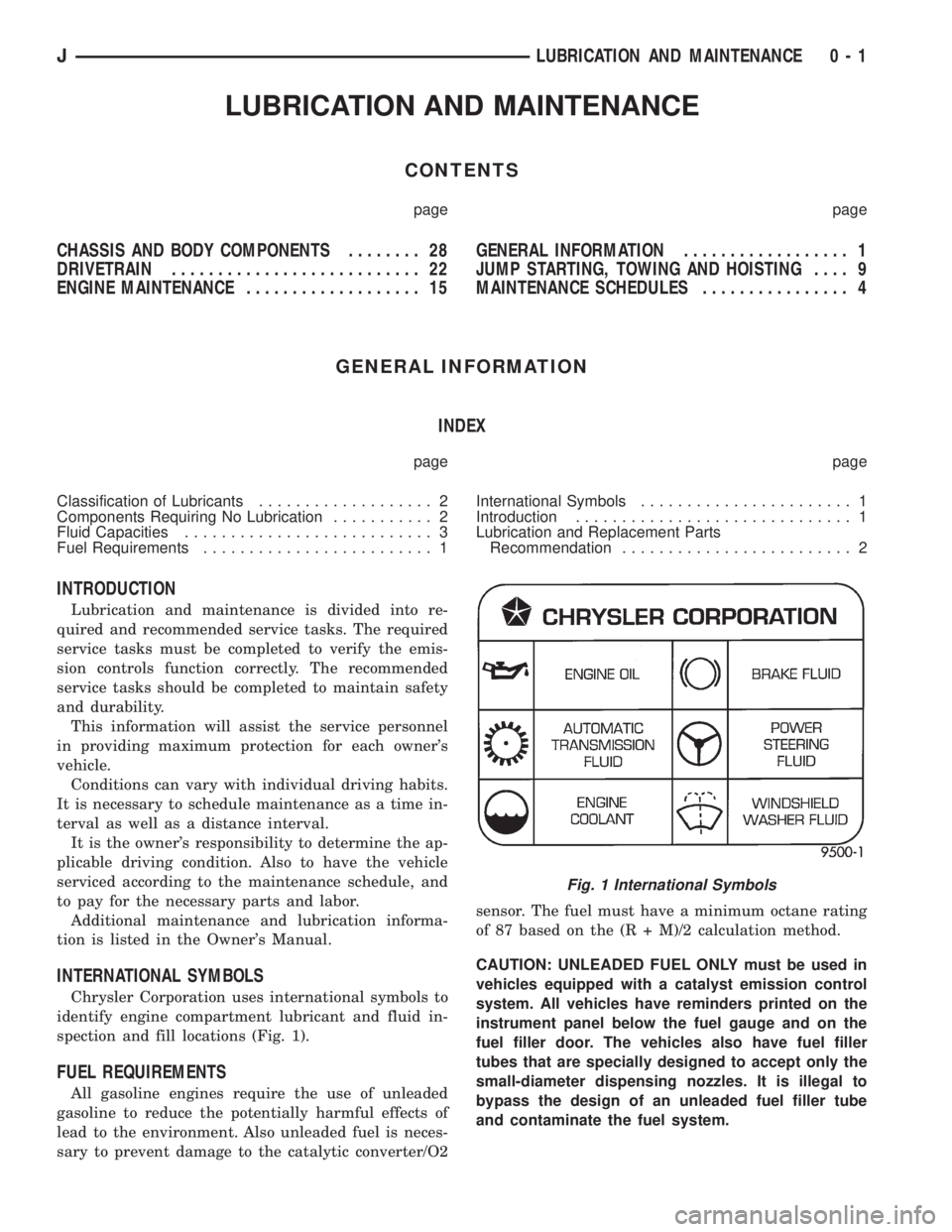
Chrysler Corporation uses international symbols to
identify engine compartment lubricant and fluid in-
spection and fill locations (Fig. 1).
FUEL REQUIREMENTS
All gasoline engines require the use of unleaded
gasoline to reduce the potentially harmful effects of
lead to the environment. Also unleaded fuel is neces-
sary to prevent damage to the catalytic converter/O2sensor. The fuel must have a minimum octane rating
of 87 based on the (R + M)/2 calculation method.
CAUTION: UNLEADED FUEL ONLY must be used in
vehicles equipped with a catalyst emission control
system. All vehicles have reminders printed on the
instrument panel below the fuel gauge and on the
fuel filler door. The vehicles also have fuel filler
tubes that are specially designed to accept only the
small-diameter dispensing nozzles. It is illegal to
bypass the design of an unleaded fuel filler tube
and contaminate the fuel system.
Fig. 1 International Symbols
JLUBRICATION AND MAINTENANCE 0 - 1
Page 34 of 2198

(5) Extra close attention should also be given to
the hood latch components to ensure proper function-
ing.
HEADLAMPS
MAINTENANCE SCHEDULE
Every six months check the headlamp beams to en-
sure that the headlamp beams are correctly posi-
tioned.
AIM ADJUSTMENT
Refer to Group 8L, Lamps for headlamp aim ad-
justment procedures.
SPEEDOMETER CABLE
SERVICE INFORMATION
Speedometer cable lubrication is not necessary. For
service information involving noisy cables, refer to
Group 8E, Instrument Panel and Gauges.
BODY LUBRICANT SPECIFICATIONS
Fig. 11 Hood Hinge LubricationÐXJ Vehicles
JLUBRICATION AND MAINTENANCE 0 - 33
Page 138 of 2198
BRAKES
CONTENTS
page page
ABS BRAKE DIAGNOSIS................... 3
ABS OPERATION AND SERVICE............ 33
BRAKE FLUIDÐBRAKE BLEEDINGÐ
BRAKELINES AND HOSES............... 10
DISC BRAKES.......................... 45
DRUM BRAKES......................... 55
GENERAL INFORMATION.................. 1MASTER CYLINDERÐCOMBINATION VALVE . . 15
PARKING BRAKES....................... 60
POWER BRAKE BOOSTERÐBRAKE PEDALÐ
BRAKELIGHT SWITCH.................. 22
SERVICE BRAKE DIAGNOSIS............... 4
SPECIFICATIONS........................ 70
GENERAL INFORMATION
INDEX
page page
Antilock Brakes (ABS)....................... 1
Brake Components......................... 1
Brake Fluid/Lubricants/Cleaning Solvents......... 2
Brake Safety Precautions.................... 2Brake Warning Lights....................... 1
Brakelining Material........................ 1
Jeep Body Code Letters..................... 2
BRAKE COMPONENTS
Power assist front disc and rear drum brakes are
standard on Cherokee/Wrangler models. Disc brake
components consist of single piston calipers and ven-
tilated rotors. Rear drum brakes are dual shoe units
with cast brake drums.
The parking brake mechanism is lever and cable
operated. The cables are attached to levers on the
rear drum brake secondary shoes. The parking
brakes are operated by a foot pedal on YJ models and
a hand lever on XJ models.
A 205 mm dual diaphragm vacuum power brake
booster is used for all applications. Two master cylin-
ders are used; 4-cylinder YJ models have a one-piece
master cylinder. All other models have a two-piece
master cylinder with plastic reservoir.
All models are equipped with a combination valve.
The valve contains a pressure differential valve and
switch and a fixed rate rear proportioning valve.
BRAKELINING MATERIAL
Factory brakelining on all models consists of an or-
ganic base material combined with metallic particles.
The lining does not contain asbestos.
BRAKE WARNING LIGHTS
Cherokee/Wrangler models are equipped with one
or two brake warning lights. A red warning light is
standard on all models. An amber light is added on
models with ABS brakes. Both lights are located in
the instrument panel.
The red light is in circuit with the pressure differ-
ential switch (in the combination valve), and with the
parking brake switch. The light alerts the driver
when the parking brakes are applied, or when a
pressure differential exists between the front and
rear hydraulic systems. The light also illuminates for
a few seconds at start up as part of a bulb check.
The ABS warning light is amber in color and is lo-
cated in the same side of the instrument cluster as
the red warning light. The amber light only illumi-
nates when an ABS circuit fault occurs.
ANTILOCK BRAKES (ABS)
An antilock brake system (ABS) is available on
Cherokee/Wrangler models as an option. The system
is an electronically operated, all-wheel brake control
system. The ABS system is designed to prevent
wheel lockup during periods of high wheel slip brak-
ing. Refer to the antilock brake section for operation
and service information.
JBRAKES 5 - 1
Page 140 of 2198
ABS BRAKE DIAGNOSIS
INDEX
page page
ABS Diagnostic Connector................... 3
ABS Warning Light Display................... 3
Antilock ECU and Hcu Diagnosis............... 3
DRB Scan Tool............................ 3General Information........................ 3
Normal Operating Conditions.................. 3
Wheel/Tire Size and Input Signals.............. 3
GENERAL INFORMATION
The DRB scan tool is required for ABS diagnosis.
The scan tool is used to identify ABS circuit faults.
Once a faulty circuit has been identified, refer to
the appropriate chassis/body diagnostic manual for
individual component testing.
ABS WARNING LIGHT DISPLAY
The amber antilock light illuminates at startup as
part of the system self check feature. The light illu-
minates for 2-3 seconds then goes off as part of the
normal check routine.
An ABS circuit fault is indicated when the amber
light remains on after startup, or illuminates during
vehicle operation.
Verify that a fault is actually related to the ABS
system before making repairs. For example, if the
red warning illuminates but the ABS light does not,
the problem is related to a service brake component
and not the ABS system. Or, if neither light illumi-
nates but a brake problem is noted, again, the prob-
lem is with a service brake component and not with
the ABS system.
ABS DIAGNOSTIC CONNECTOR
The ABS diagnostic connector is inside the vehicle.
The connector is the access point for the DRB scan tool.
On XJ models, the connector is located under the
instrument panel to the right of the steering column.
On some models, the connecter may be tucked under
the carpeting on the transmission tunnel. The con-
necter is a black, 6-way type.
On YJ models, the connector is under the instru-
ment panel by the the driver side kick panel. The
connecter is a black, 6 or 8-way type.
The DRB scan tool kit contains adapter cords for
both types of connecter. Use the appropriate cord for
test hookup.
DRB SCAN TOOL
ABS diagnosis is performed with the DRB scan tool.
Refer to the DRB scan tool manual for test hookup and
procedures. Diagnosis information is provided in the ap-
propriate chassis/body diagnostic manual.
WHEEL/TIRE SIZE AND INPUT SIGNALS
Antilock system operation is dependant on accurate
signals from the wheel speed sensors. Ideally, the ve-
hicle wheels and tires should all be the same size
and type. However, the Jeep ABS system is designed
to operate with a compact spare tire installed.
NORMAL OPERATING CONDITIONS
Sound Levels
The hydraulic control unit pump and solenoid valves
may produce some sound as they cycle on and off. This
is a normal condition and should not be mistaken for
faulty operation. Under most conditions, pump and so-
lenoid valve operating sounds will not be audible.
Vehicle Response In Antilock Mode
During antilock braking, the hydraulic control unit
solenoid valves cycle rapidly in response to antilock
electronic control unit signals.
The driver will experience a pulsing sensation
within the vehicle as the solenoids decrease, hold, or
increase pressure as needed. Brake pedal pulsing will
also be noted and is anormal condition.
Steering Response
A modest amount of steering input is required dur-
ing extremely high deceleration braking, or when
braking on differing traction surfaces. An example of
differing traction surfaces would be when the left
side wheels are on ice and the right side wheels are
on dry pavement.
Owner Induced Faults
Driving away with the parking brakes still applied
will cause warning light illumination. Pumping the
brake pedal will also generate a system fault and in-
terfere with ABS system operation.
ANTILOCK ECU AND HCU DIAGNOSIS
An ECU or HCU fault can only be determined
through testing with the DRB scan tool. Do not re-
place either component unless a fault is actually in-
dicated.
JABS BRAKE DIAGNOSIS 5 - 3
Page 148 of 2198
bubbles that are distributed throughout the hydrau-
lic system. This will make extra bleeding operations
necessary.
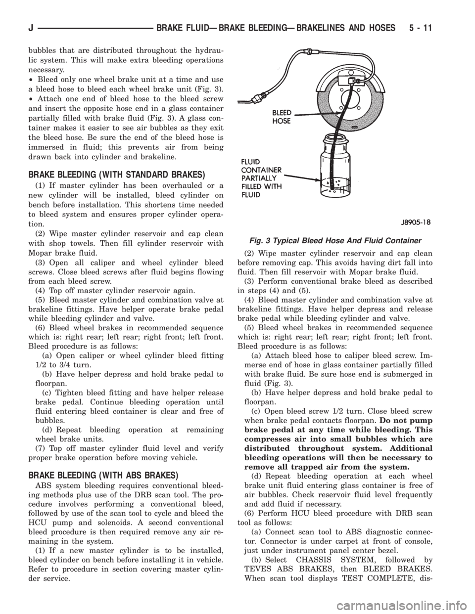
²Bleed only one wheel brake unit at a time and use
a bleed hose to bleed each wheel brake unit (Fig. 3).
²Attach one end of bleed hose to the bleed screw
and insert the opposite hose end in a glass container
partially filled with brake fluid (Fig. 3). A glass con-
tainer makes it easier to see air bubbles as they exit
the bleed hose. Be sure the end of the bleed hose is
immersed in fluid; this prevents air from being
drawn back into cylinder and brakeline.
BRAKE BLEEDING (WITH STANDARD BRAKES)
(1) If master cylinder has been overhauled or a
new cylinder will be installed, bleed cylinder on
bench before installation. This shortens time needed
to bleed system and ensures proper cylinder opera-
tion.
(2) Wipe master cylinder reservoir and cap clean
with shop towels. Then fill cylinder reservoir with
Mopar brake fluid.
(3) Open all caliper and wheel cylinder bleed
screws. Close bleed screws after fluid begins flowing
from each bleed screw.
(4) Top off master cylinder reservoir again.
(5) Bleed master cylinder and combination valve at
brakeline fittings. Have helper operate brake pedal
while bleeding cylinder and valve.
(6) Bleed wheel brakes in recommended sequence
which is: right rear; left rear; right front; left front.
Bleed procedure is as follows:
(a) Open caliper or wheel cylinder bleed fitting
1/2 to 3/4 turn.
(b) Have helper depress and hold brake pedal to
floorpan.
(c) Tighten bleed fitting and have helper release
brake pedal. Continue bleeding operation until
fluid entering bleed container is clear and free of
bubbles.
(d) Repeat bleeding operation at remaining
wheel brake units.
(7) Top off master cylinder fluid level and verify
proper brake operation before moving vehicle.
BRAKE BLEEDING (WITH ABS BRAKES)
ABS system bleeding requires conventional bleed-
ing methods plus use of the DRB scan tool. The pro-
cedure involves performing a conventional bleed,
followed by use of the scan tool to cycle and bleed the
HCU pump and solenoids. A second conventional
bleed procedure is then required remove any air re-
maining in the system.
(1) If a new master cylinder is to be installed,
bleed cylinder on bench before installing it in vehicle.
Refer to procedure in section covering master cylin-
der service.(2) Wipe master cylinder reservoir and cap clean
before removing cap. This avoids having dirt fall into
fluid. Then fill reservoir with Mopar brake fluid.
(3) Perform conventional brake bleed as described
in steps (4) and (5).
(4) Bleed master cylinder and combination valve at
brakeline fittings. Have helper depress and release
brake pedal while bleeding cylinder and valve.
(5) Bleed wheel brakes in recommended sequence
which is: right rear; left rear; right front; left front.
Bleed procedure is as follows:
(a) Attach bleed hose to caliper bleed screw. Im-
merse end of hose in glass container partially filled
with brake fluid. Be sure hose end is submerged in
fluid (Fig. 3).
(b) Have helper depress and hold brake pedal to
floorpan.
(c) Open bleed screw 1/2 turn. Close bleed screw
when brake pedal contacts floorpan.Do not pump
brake pedal at any time while bleeding. This
compresses air into small bubbles which are
distributed throughout system. Additional
bleeding operations will then be necessary to
remove all trapped air from the system.
(d) Repeat bleeding operation at each wheel
brake unit fluid entering glass container is free of
air bubbles. Check reservoir fluid level frequently
and add fluid if necessary.
(6) Perform HCU bleed procedure with DRB scan
tool as follows:
(a) Connect scan tool to ABS diagnostic connec-
tor. Connector is under carpet at front of console,
just under instrument panel center bezel.
(b) Select CHASSIS SYSTEM, followed by
TEVES ABS BRAKES, then BLEED BRAKES.
When scan tool displays TEST COMPLETE, dis-
Fig. 3 Typical Bleed Hose And Fluid Container
JBRAKE FLUIDÐBRAKE BLEEDINGÐBRAKELINES AND HOSES 5 - 11
Page 159 of 2198
POWER BRAKE BOOSTERÐBRAKE PEDALÐBRAKELIGHT SWITCH
INDEX
page page
Brake Pedal Installation..................... 31
Brake Pedal Removal...................... 31
Brakelight Switch Adjustment................. 32
Brakelight Switch Installation................. 32
Brakelight Switch Removal.................. 32
General Information....................... 22
Power Brake Booster Installation (XJ with ABS) . . . 27
Power Brake Booster Installation (XJ Without ABS).. 30
Power Brake Booster Installation (YJ).......... 30
Power Brake Booster Operation.............. 23
Power Brake Booster Removal (XJ with ABS).... 24
Power Brake Booster Removal (XJ Without ABS) . . 29
Power Brake Booster Removal (YJ)............ 30
GENERAL INFORMATION
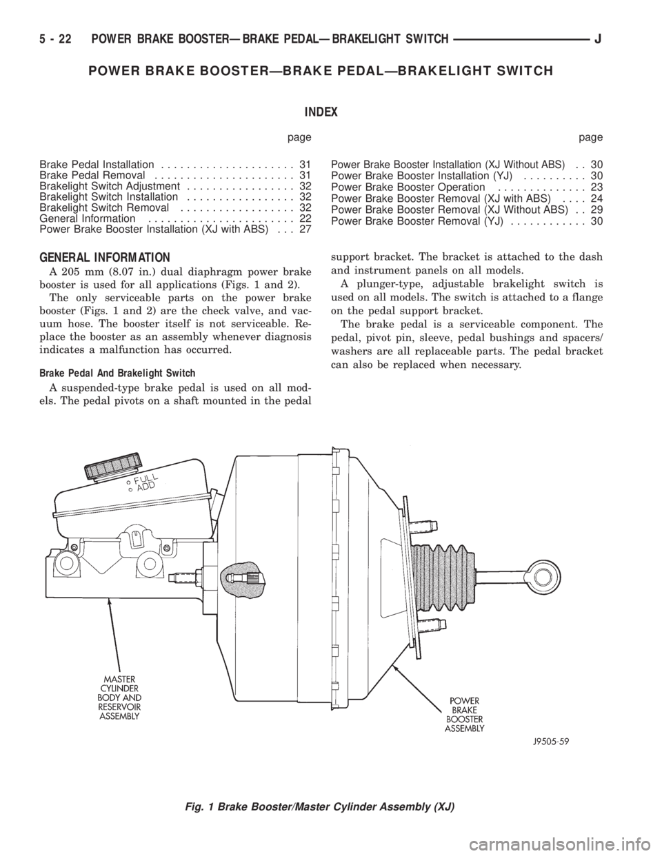
A 205 mm (8.07 in.) dual diaphragm power brake
booster is used for all applications (Figs. 1 and 2).
The only serviceable parts on the power brake
booster (Figs. 1 and 2) are the check valve, and vac-
uum hose. The booster itself is not serviceable. Re-
place the booster as an assembly whenever diagnosis
indicates a malfunction has occurred.
Brake Pedal And Brakelight Switch
A suspended-type brake pedal is used on all mod-
els. The pedal pivots on a shaft mounted in the pedalsupport bracket. The bracket is attached to the dash
and instrument panels on all models.
A plunger-type, adjustable brakelight switch is
used on all models. The switch is attached to a flange
on the pedal support bracket.
The brake pedal is a serviceable component. The
pedal, pivot pin, sleeve, pedal bushings and spacers/
washers are all replaceable parts. The pedal bracket
can also be replaced when necessary.
Fig. 1 Brake Booster/Master Cylinder Assembly (XJ)
5 - 22 POWER BRAKE BOOSTERÐBRAKE PEDALÐBRAKELIGHT SWITCHJ
Page 166 of 2198
(16) Install combination valve as follows:
(a) Work combination valve and brakelines into
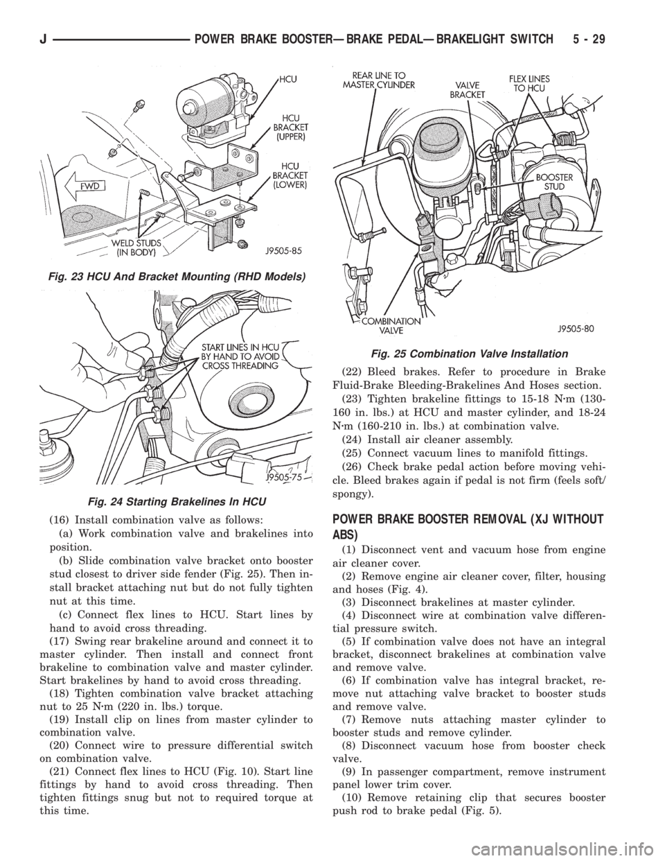
position.
(b) Slide combination valve bracket onto booster
stud closest to driver side fender (Fig. 25). Then in-
stall bracket attaching nut but do not fully tighten
nut at this time.
(c) Connect flex lines to HCU. Start lines by
hand to avoid cross threading.
(17) Swing rear brakeline around and connect it to
master cylinder. Then install and connect front
brakeline to combination valve and master cylinder.
Start brakelines by hand to avoid cross threading.
(18) Tighten combination valve bracket attaching
nut to 25 Nzm (220 in. lbs.) torque.
(19) Install clip on lines from master cylinder to
combination valve.
(20) Connect wire to pressure differential switch
on combination valve.
(21) Connect flex lines to HCU (Fig. 10). Start line
fittings by hand to avoid cross threading. Then
tighten fittings snug but not to required torque at
this time.(22) Bleed brakes. Refer to procedure in Brake
Fluid-Brake Bleeding-Brakelines And Hoses section.
(23) Tighten brakeline fittings to 15-18 Nzm (130-
160 in. lbs.) at HCU and master cylinder, and 18-24
Nzm (160-210 in. lbs.) at combination valve.
(24) Install air cleaner assembly.
(25) Connect vacuum lines to manifold fittings.
(26) Check brake pedal action before moving vehi-
cle. Bleed brakes again if pedal is not firm (feels soft/
spongy).POWER BRAKE BOOSTER REMOVAL (XJ WITHOUT
ABS)
(1) Disconnect vent and vacuum hose from engine
air cleaner cover.
(2) Remove engine air cleaner cover, filter, housing
and hoses (Fig. 4).
(3) Disconnect brakelines at master cylinder.
(4) Disconnect wire at combination valve differen-
tial pressure switch.
(5) If combination valve does not have an integral
bracket, disconnect brakelines at combination valve
and remove valve.
(6) If combination valve has integral bracket, re-
move nut attaching valve bracket to booster studs
and remove valve.
(7) Remove nuts attaching master cylinder to
booster studs and remove cylinder.
(8) Disconnect vacuum hose from booster check
valve.
(9) In passenger compartment, remove instrument
panel lower trim cover.
(10) Remove retaining clip that secures booster
push rod to brake pedal (Fig. 5).
Fig. 23 HCU And Bracket Mounting (RHD Models)
Fig. 24 Starting Brakelines In HCU
Fig. 25 Combination Valve Installation
JPOWER BRAKE BOOSTERÐBRAKE PEDALÐBRAKELIGHT SWITCH 5 - 29
Page 167 of 2198
(11) Remove nuts attaching booster to passenger
compartment side of dash panel.
(12) In engine compartment, slide booster studs
out of dash panel, tilt booster upward, and remove
booster from engine compartment.
(13) Remove dash seal from booster.
(14) If booster is only being removed for access to
other components, cover booster front opening with
clean shop towel.
POWER BRAKE BOOSTER INSTALLATION (XJ
WITHOUT ABS)
(1) If original booster is being installed, test check
valve with vacuum tool before booster installation.
Replace check valve if it will not hold vacuum.
(2) Install dash seal on booster.
(3) Align and position booster on dash panel (Fig.
17).
(4) In passenger compartment, install nuts that at-
tach booster to dash panel. Tighten nuts just enough
to hold booster in place.
(5) Slide booster push rod onto brake pedal. Then
secure push rod to pedal pin with retaining clip.
(6) Tighten booster attaching nuts to 41 Nzm (30 ft.
lbs.) on XJ and 34 Nzm (25 ft. lbs.) on YJ.
(7) Install instrument panel lower trim cover.
(8) If original master cylinder is being installed,
check condition of seal at rear of master cylinder
(Fig. 18). Clean and reposition seal if dislodged. Re-
place seal if cut, or torn.
(9) Clean cylinder mounting surface of brake
booster. Use shop towel wetted with brake cleaner for
this purpose. Dirt, grease, or similar materials will
prevent proper cylinder seating and could result in
vacuum leak.
(10) Align and install master cylinder on booster
studs. Tighten cylinder attaching nuts to 13-25 Nzm
(115-220 in. lbs.) torque.
(11) Connect vacuum hose to booster check valve.
(12) Connect and secure brakelines to combination
valve and master cylinder. Start all brakeline fittings
by hand to avoid cross threading.
(13) If combination valve has integral bracket, po-
sition bracket on booster studs. Then install and
tighten bracket attaching nuts to 13-25 Nzm (115-220
in. lbs.) torque.
(14) Connect wire to combination valve switch.
(15) Top off master cylinder fluid level.
(16) Bleed brakes. Refer to procedures in section
on brake bleeding.
(17) Install engine air cleaner and hoses.
(18) Verify proper brake operation before moving
vehicle.
POWER BRAKE BOOSTER REMOVAL (YJ)
(1) Disconnect brakelines at master cylinder. Then
loosen lines at combination valve and move lines
away from cylinder.
(2) Remove nuts master cylinder to booster studs.
(3) If combination valve has integral bracket, slide
bracket off studs and move valve aside.
(4) Remove master cylinder. Slide cylinder off
studs and remove it from engine compartment.
(5) Working under instrument panel, remove re-
tainer clip that secures booster push rod to brake
pedal.
(6) Disconnect vacuum hose at booster check valve.
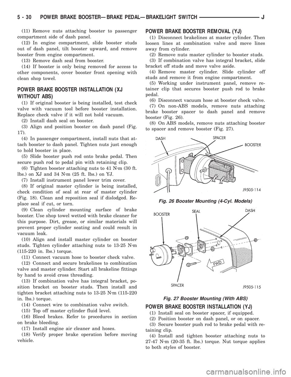
(7) On non-ABS models, remove nuts attaching
brake booster spacer to dash panel and remove
booster (Fig. 26).
(8) On ABS models, remove nuts attaching booster
to spacer and remove booster (Fig. 27).
POWER BRAKE BOOSTER INSTALLATION (YJ)
(1) Install seal on booster spacer, if equipped.
(2) Position booster on dash panel, or on spacer.
(3) Secure booster push rod to brake pedal with re-
taining clip.
(4) Install and tighten booster attaching nuts to
27-47 Nzm (20-35 ft. lbs.) torque. Nut torque applies
to both styles of booster.
Fig. 26 Booster Mounting (4-Cyl. Models)
Fig. 27 Booster Mounting (With ABS)
5 - 30 POWER BRAKE BOOSTERÐBRAKE PEDALÐBRAKELIGHT SWITCHJ