1995 JEEP CHEROKEE seat adjustment
[x] Cancel search: seat adjustmentPage 175 of 2198
air gap should be 0.40 to 1.3 mm (0.0157 to 0.051
in.). If gap is incorrect, the sensor is either loose, or
damaged.
A rear sensor air gap adjustment is only needed
when reinstalling an original sensor. Replacement
sensors have an air gap spacer attached to the sensor
pickup face. The spacer establishes correct air gap
when pressed against the tone ring during installa-
tion. As the tone ring rotates, it peels the spacer off
the sensor to create the required air gap. Rear sensor
air gap is 0.92-1.45 mm (0.036-0.057 in.).
Sensor air gap measurement, or adjustment proce-
dures are provided in this section. Refer to the front,
or rear sensor removal and installation procedures as
required.
FRONT WHEEL SENSOR REMOVAL
(1) Raise vehicle and turn wheel outward for easier
access to sensor.
(2) Remove sensor wire from mounting brackets.
(3) Clean sensor and surrounding area with shop
towel before removal.
(4) Remove bolt attaching sensor to steering
knuckle and remove sensor.
(5) remove sensor wire from brackets on body and
steering knuckle.
(6) Unseat sensor wire grommet in wheel house
panel.
(7) In engine compartment, disconnect sensor wire
connector at harness plug. Then remove sensor and
wire.
FRONT WHEEL SENSOR INSTALLATION
(1) Iforiginalsensor will be installed, wipe all
traces of old spacer material off sensor pickup face.
Use a dry shop towel for this purpose.
(2) Apply Mopar Lock N' Seal or Loctite 242 to bolt
that secures sensor in steering knuckle. Use new
sensor bolt if original bolt is worn or damaged.
(3) Position sensor on steering knuckle. Seat sen-
sor locating tab in hole in knuckle and install sensor
attaching bolt finger tight.
(4) Tighten sensor attaching bolt to 14 Nzm (11 ft.
lbs.) torque.
(5) If original sensor has been installed, check sen-
sor air gap. Air gap should be 0.40 to 1.3 mm (0.0157
to 0.051 in.). If gap is incorrect, sensor is either loose,
or damaged.
(6) Secure sensor wire to steering knuckle and
body brackets.
(7) Route sensor wire forward and behind shock
absorber. Then attach sensor wire to spring seat
bracket with grommets on sensor wire.
(8) Route sensor wire to outer sill bracket. Remove
all twists or kinks from wire.
(9) Attach sensor wire to sill bracket with grom-
met. Be sure wire is free of twists and kinks.(10) Verify sensor wire routing. Wire should loop
forward and above sill bracket. Loose end of wire
should be below sill bracket and towards brake hose.
(11) Seat sensor wire grommet in body panel and
clip wire to brake line at grommet location.
(12) Connect sensor wire to harness in engine com-
partment.
REAR WHEEL SENSOR REMOVAL
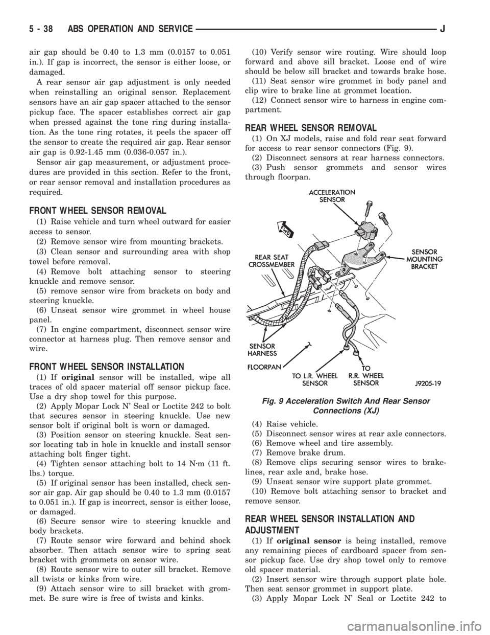
(1) On XJ models, raise and fold rear seat forward
for access to rear sensor connectors (Fig. 9).
(2) Disconnect sensors at rear harness connectors.
(3) Push sensor grommets and sensor wires
through floorpan.
(4) Raise vehicle.
(5) Disconnect sensor wires at rear axle connectors.
(6) Remove wheel and tire assembly.
(7) Remove brake drum.
(8) Remove clips securing sensor wires to brake-
lines, rear axle and, brake hose.
(9) Unseat sensor wire support plate grommet.
(10) Remove bolt attaching sensor to bracket and
remove sensor.
REAR WHEEL SENSOR INSTALLATION AND
ADJUSTMENT
(1) Iforiginal sensoris being installed, remove
any remaining pieces of cardboard spacer from sen-
sor pickup face. Use dry shop towel only to remove
old spacer material.
(2) Insert sensor wire through support plate hole.
Then seat sensor grommet in support plate.
(3) Apply Mopar Lock N' Seal or Loctite 242 to
Fig. 9 Acceleration Switch And Rear Sensor
Connections (XJ)
5 - 38 ABS OPERATION AND SERVICEJ
Page 188 of 2198
CALIPER INSTALLATION
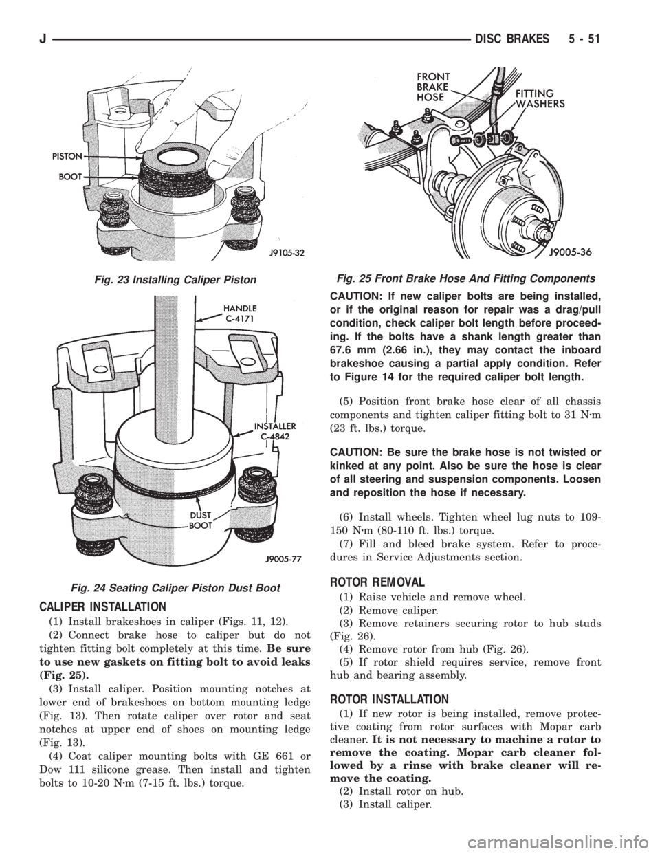
(1) Install brakeshoes in caliper (Figs. 11, 12).
(2) Connect brake hose to caliper but do not
tighten fitting bolt completely at this time.Be sure
to use new gaskets on fitting bolt to avoid leaks
(Fig. 25).
(3) Install caliper. Position mounting notches at
lower end of brakeshoes on bottom mounting ledge
(Fig. 13). Then rotate caliper over rotor and seat
notches at upper end of shoes on mounting ledge
(Fig. 13).
(4) Coat caliper mounting bolts with GE 661 or
Dow 111 silicone grease. Then install and tighten
bolts to 10-20 Nzm (7-15 ft. lbs.) torque.CAUTION: If new caliper bolts are being installed,
or if the original reason for repair was a drag/pull
condition, check caliper bolt length before proceed-
ing. If the bolts have a shank length greater than
67.6 mm (2.66 in.), they may contact the inboard
brakeshoe causing a partial apply condition. Refer
to Figure 14 for the required caliper bolt length.
(5) Position front brake hose clear of all chassis
components and tighten caliper fitting bolt to 31 Nzm
(23 ft. lbs.) torque.
CAUTION: Be sure the brake hose is not twisted or
kinked at any point. Also be sure the hose is clear
of all steering and suspension components. Loosen
and reposition the hose if necessary.
(6) Install wheels. Tighten wheel lug nuts to 109-
150 Nzm (80-110 ft. lbs.) torque.
(7) Fill and bleed brake system. Refer to proce-
dures in Service Adjustments section.
ROTOR REMOVAL
(1) Raise vehicle and remove wheel.
(2) Remove caliper.
(3) Remove retainers securing rotor to hub studs
(Fig. 26).
(4) Remove rotor from hub (Fig. 26).
(5) If rotor shield requires service, remove front
hub and bearing assembly.
ROTOR INSTALLATION
(1) If new rotor is being installed, remove protec-
tive coating from rotor surfaces with Mopar carb
cleaner.It is not necessary to machine a rotor to
remove the coating. Mopar carb cleaner fol-
lowed by a rinse with brake cleaner will re-
move the coating.
(2) Install rotor on hub.
(3) Install caliper.
Fig. 23 Installing Caliper Piston
Fig. 24 Seating Caliper Piston Dust Boot
Fig. 25 Front Brake Hose And Fitting Components
JDISC BRAKES 5 - 51
Page 203 of 2198
PARKING BRAKE CABLE TENSIONER
REPLACEMENT (XJ)
(1) Raise vehicle.
(2) Remove adjuster nut from tensioner rod. Secure
equalizer and cables to nearby chassis component
with wire.
(3) Remove nuts attaching lever assembly to sup-
port plate and floorpan.
(4) Lower vehicle.
(5) Remove console components and lever assembly
cover.
(6) Remove lever and tensioner assembly.
(7) Move cover and boot for access to tensioner re-
taining pin.
(8) Remove E-clip and pin that attach tensioner to
lever arm (Fig. 4).
(9) Remove tensioner from cover.
(10) Transfer boot to new tensioner if necessary.
(11) Attach tensioner to lever arm with pin and E-
clip.
(12) Verify that E-clip is fully engaged in pin (Fig.
4).
(13) Align cover and seal on lever flange.
(14) Verify that tensioner boot is seated in cover
(Fig. 6).
(15) Install assembled lever and tensioner in floor-
pan.
(16) Install necessary console components.
(17) Adjust parking brakes as described in this sec-
tion.
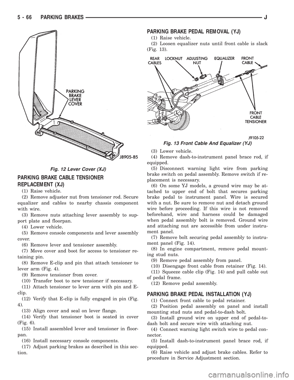
PARKING BRAKE PEDAL REMOVAL (YJ)
(1) Raise vehicle.
(2) Loosen equalizer nuts until front cable is slack
(Fig. 13).
(3) Lower vehicle.
(4) Remove dash-to-instrument panel brace rod, if
equipped.
(5) Disconnect warning light wire from parking
brake switch on pedal assembly. Remove switch if re-
placement is necessary.
(6) On some YJ models, a ground wire may be at-
tached to upper end of bolt that secures parking
brake pedal to instrument panel. Wire is secured
with a nut. Be sure to remove nut and detach ground
wire before proceeding. If this wire is not removed
beforehand, wire and harness could be damaged
when pedal assembly bolt is removed. Ground wire
and attaching nut are accessible from under instru-
ment panel.
(7) Remove bolt securing pedal assembly to instru-
ment panel (Fig. 14).
(8) In engine compartment, remove pedal mount-
ing stud nuts.
(9) Remove pedal assembly from panel.
(10) Disengage front cable from retainer (Fig. 14).
(11) Squeeze cable clip (Fig. 14) and pull cable out
of pedal frame.
(12) Remove pedal assembly.
PARKING BRAKE PEDAL INSTALLATION (YJ)
(1) Connect front cable to pedal retainer.
(2) Position pedal assembly on panel and install
mounting stud nuts and pedal-to-dash bolt.
(3) Install ground wire on upper end of pedal-to-
dash bolt and secure wire with attaching nut.
(4) Connect warning light switch wire to pedal con-
nector.
(5) Install dash-to-instrument panel brace rod, if
equipped.
(6) Raise vehicle and adjust brake cables. Refer to
procedure in Service Adjustment section.
Fig. 12 Lever Cover (XJ)
Fig. 13 Front Cable And Equalizer (YJ)
5 - 66 PARKING BRAKESJ
Page 204 of 2198
PARKING BRAKE REAR CABLE REPLACEMENT (XJ)
(1) Raise vehicle and loosen equalizer nuts until
rear cables are slack.
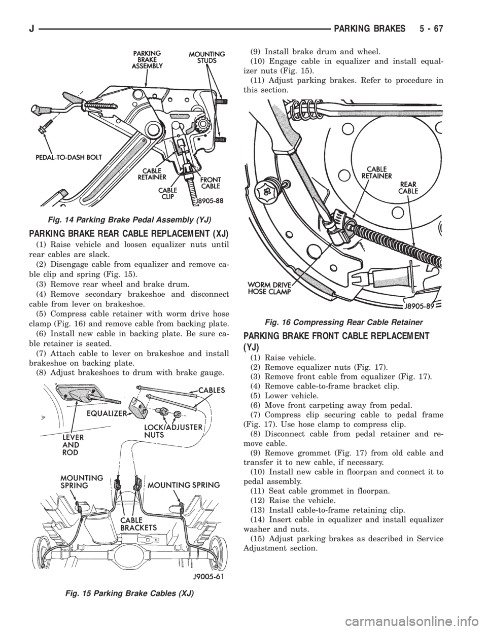
(2) Disengage cable from equalizer and remove ca-
ble clip and spring (Fig. 15).
(3) Remove rear wheel and brake drum.
(4) Remove secondary brakeshoe and disconnect
cable from lever on brakeshoe.
(5) Compress cable retainer with worm drive hose
clamp (Fig. 16) and remove cable from backing plate.
(6) Install new cable in backing plate. Be sure ca-
ble retainer is seated.
(7) Attach cable to lever on brakeshoe and install
brakeshoe on backing plate.
(8) Adjust brakeshoes to drum with brake gauge.(9) Install brake drum and wheel.
(10) Engage cable in equalizer and install equal-
izer nuts (Fig. 15).
(11) Adjust parking brakes. Refer to procedure in
this section.
PARKING BRAKE FRONT CABLE REPLACEMENT
(YJ)
(1) Raise vehicle.
(2) Remove equalizer nuts (Fig. 17).
(3) Remove front cable from equalizer (Fig. 17).
(4) Remove cable-to-frame bracket clip.
(5) Lower vehicle.
(6) Move front carpeting away from pedal.
(7) Compress clip securing cable to pedal frame
(Fig. 17). Use hose clamp to compress clip.
(8) Disconnect cable from pedal retainer and re-
move cable.
(9) Remove grommet (Fig. 17) from old cable and
transfer it to new cable, if necessary.
(10) Install new cable in floorpan and connect it to
pedal assembly.
(11) Seat cable grommet in floorpan.
(12) Raise the vehicle.
(13) Install cable-to-frame retaining clip.
(14) Insert cable in equalizer and install equalizer
washer and nuts.
(15) Adjust parking brakes as described in Service
Adjustment section.
Fig. 14 Parking Brake Pedal Assembly (YJ)
Fig. 15 Parking Brake Cables (XJ)
Fig. 16 Compressing Rear Cable Retainer
JPARKING BRAKES 5 - 67
Page 972 of 2198
POWER MIRRORS
INDEX
page page
Diagram Index............................ 1
Heater Elements........................... 1Power Mirrors............................. 1
POWER MIRRORS
Four switches operates the left and right power
mirrors. One switch selects right or left mirror. Each
mirror has two motors; a LEFT/RIGHT motor and a
UP/DOWN motor. The motors switch polarity to al-
low mirror adjustment.
Circuit A7 from fuse 13 in the Power Distribution
Center (PDC) supplies battery voltage to fuse 8 in
the fuse block. Fuse 8 supplies voltage to circuit P60.
Circuit P60 powers the power mirror switch. Circuit
Z1 connects to the power mirror switch and supplies
ground for the power mirror system.
RIGHT POWER MIRROR OPERATION
In the right position, the power mirror switch sup-
plies power to the right mirror LEFT/RIGHT motor
on circuit P79 when a rightward adjustment is made.
Circuit P77 provides the ground path the for right-
ward adjustments.
When the operator makes leftward adjustment, po-
larity reverses. For leftward adjustments, the switch
supplies battery voltage to the right mirror LEFT/
RIGHT motor on circuit P77. Circuit P79 supplies
ground for leftward adjustments.
During upward adjustments, the switch supplies
voltage to the right mirror UP/DOWN motor on cir-
cuit P79. Circuit P80 supplies ground during upward
adjustments.
For downward adjustments, the polarity is re-
versed, the switch powers the right mirror UP/
DOWN motor on circuit P80. Circuit P79 supplies the
ground path.
LEFT POWER MIRROR OPERATION
In the left position, the power mirror switch sup-
plies power to the left mirror LEFT/RIGHT motor on
circuit P79 when a rightward adjustment is made.
Circuit P81 provides the ground path the for right-
ward adjustments.
When the operator makes leftward adjustment, po-
larity reverses. For leftward adjustments, the switch
supplies battery voltage the left mirror LEFT/RIGHT
motor on circuit P81. Circuit P79 supplies ground for
leftward adjustments.
During upward adjustments, the switch supplies
voltage to the left mirror UP/DOWN motor on circuit
P79. Circuit P78 supplies ground during upward ad-
justments.For downward adjustments, the polarity is re-
versed, the switch powers the left mirror UP/DOWN
motor on circuit P78. Circuit P79 supplies the ground
path.
HELPFUL INFORMATION
²Check fuse 3 in the PDC and fuse 8 in the fuse
block in the PDC
HEATER ELEMENTS
The heated rear window relay powers the heater
elements in power mirrors. When the relay energizes,
it supplies power to the heater elements on circuit
C15. Circuit Z1 provides ground for the power mirror
heater elements.
HELPFUL INFORMATION
²Circuit F82 from fuse 2 in the fuse block powers
circuit C15 when the heated rear window relay ener-
gizes.
²Circuit A4 from fuse 7 in the Power Distribution
Center (PDC) supplies battery voltage to the fuse
block for fuse 2 and circuit F85.
²Check fuse 2 in the fuse block.
²Check fuse 7 in the PDC.
DIAGRAM INDEX
Component Page
Fuse 1 (Fuse Block).......................8W-63-2
Fuse 3 (PDC)...........................8W-63-2
Power Seat............................8W-63-2
Power Seat Switch.......................8W-63-2
Fuse 2 (Fuse Block).......................8W-62-3
Fuse 3 (PDC)...........................8W-62-2
Fuse 7 (Fuse Block).......................8W-62-2
Fuse 7 (PDC)...........................8W-62-3
Fuse 8 (Fuse Block).......................8W-62-2
Fuse 16 (PDC)..........................8W-62-2
Heated Rear Window Relay..................8W-62-3
Power Mirrors..........................8W-62-2
Power Mirror Heater Elements................8W-62-3
Power Mirror Switch......................8W-62-2
J8W-62 POWER MIRRORSÐXJ-RHD 8W - 62 - 1
Page 1093 of 2198
minutes). The use of a locating dowel is recom-
mended during assembly to prevent smearing the
material off location.
Mopar Gasket Maker should be applied sparingly
to one gasket surface. The sealant diameter should
be 1.00 mm (0.04 inch) or less. Be certain the mate-
rial surrounds each mounting hole. Excess material
can easily be wiped off. Components should be
torqued in place within 15 minutes. The use of a lo-
cating dowel is recommended during assembly to pre-
vent smearing the material off location.
ENGINE PERFORMANCE
To provide best vehicle performance and lowest ve-
hicle emissions, it is most important that the tune-up
be done accurately. Use the specifications listed on
the Vehicle Emission Control Information label found
on the engine compartment hood.
(1) Test battery specific gravity. Add water, if nec-
essary. Clean and tighten battery connections.
(2) Test cranking amperage draw (refer to Group
8B, Battery/Starter Service for the proper proce-
dures).
(3) Tighten the intake manifold bolts (refer to
Group 11, Exhaust System and Intake Manifold for
the proper specifications).
(4) Perform cylinder compression test:
(a) Check engine oil level and add oil, if neces-
sary.
(b) Drive the vehicle until engine reaches normal
operating temperature.
(c) Select a route free from traffic and other
forms of congestion, observe all traffic laws and
briskly accelerate through the gears several times.
The higher engine speed may help clean out valve
seat deposits which can prevent accurate compres-
sion readings.
CAUTION: DO NOT overspeed the engine.
(d) Remove all spark plugs from engine. As spark
plugs are being removed, check electrodes for ab-
normal firing indicatorsÐfouled, hot, oily, etc.
Record cylinder number of spark plug for future
reference.
(e) Disconnect coil wire from distributor and se-
cure to good ground to prevent a spark from start-
ing a fire.
(f) Be sure throttle blades are fully open during
the compression check.
(g) Insert compression gage adaptor into the
No.1 spark plug hole. Crank engine until maximum
pressure is reached on gauge. Record this pressure
as No.1 cylinder pressure.
(h) Repeat Step 4g for all remaining cylinders.
(i) Compression should not be less than 689 kPa
(100 psi) and not vary more than 172 kPa (25 psi)
from cylinder to cylinder.(j) If cylinder(s) have abnormally low compres-
sion pressures, repeat steps 4a through 4h.
(k) If the same cylinder(s) repeat an abnormally
low reading, it could indicate the existence of a
problem in the cylinder.
The recommended compression pressures are
to be used only as a guide to diagnosing engine
problems. An engine should NOT be disassem-
bled to determine the cause of low compression
unless some malfunction is present.
(5) Clean or replace spark plugs as necessary. Ad-
just gap (refer to Group 8D, Ignition System for gap
adjustment and torque).
(6) Test resistance of spark plug cables (refer to
Group 8D, Ignition System).
(7) Inspect the primary wire. Test coil output volt-
age, primary and secondary resistance. Replace parts
as necessary (refer to Group 8D, Ignition System and
make necessary adjustment).
(8) Perform a combustion analysis.
(9) Test fuel pump for pressure (refer to Group 14,
Fuel System for the proper specifications).
(10) Inspect air filter element (refer to Group 0,
Lubrication and Maintenance for the proper proce-
dure).
(11) Inspect crankcase ventilation system (refer to
Group 0, Lubrication and Maintenance for the proper
procedure).
(12) For emission controls refer to Group 25, Emis-
sion Controls System for service procedures.
(13) Inspect and adjust accessory belt drives (refer
to Group 7, Cooling System for the proper adjust-
ments).
(14) Road test vehicle as a final test.
HONING CYLINDER BORES
Before honing, stuff plenty of clean shop towels un-
der the bores and over the crankshaft to keep abra-
sive materials from entering the crankshaft area.
(1) Used carefully, the Cylinder Bore Sizing Hone
C-823 equipped with 220 grit stones, is the best tool
for this job. In addition to deglazing, it will reduce
taper and out-of-round as well as removing light
scuffing, scoring or scratches. Usually a few strokes
will clean up a bore and maintain the required lim-
its.
CAUTION: DO NOT use rigid type hones to remove
cylinder wall glaze.
(2) Deglazing of the cylinder walls may be done if
the cylinder bore is straight and round. Use a cylin-
der surfacing hone, Honing Tool C-3501, equipped
with 280 grit stones (C-3501-3810). 20-60 strokes, de-
pending on the bore condition, will be sufficient to
provide a satisfactory surface. Using honing oil
C-3501-3880 or a light honing oil available from ma-
jor oil distributors.
9 - 2 ENGINESJ
Page 1327 of 2198
PITMAN SHAFT AND SIDE COVER REPLACEMENT
REMOVE
(1) Remove steering gear from vehicle. Refer to
Power Steering Gear Replacement in this section.
(2) Remove pitman arm from steering gear. Refer
to Pitman Arm Removal in the Steering Linkage sec-
tion.
(3) Rotate stub shaft back and forth to drain power
steering fluid.
DISASSEMBLE
²Clean exposed end of pitman shaft and housing.
²Clean pitman shaft spline with a wire brush.
(1) Remove preload adjuster nut.
(2) Rotate stub shaft with socket to center gear.
Remove side cover bolts.
(3) Remove side cover, gasket and pitman shaft as
an assembly.
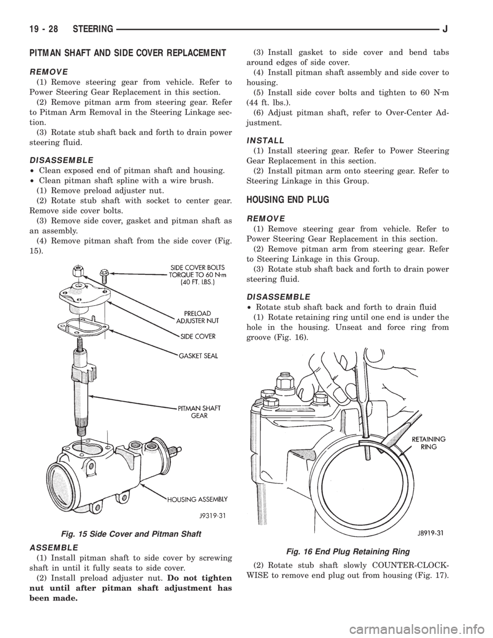
(4) Remove pitman shaft from the side cover (Fig.
15).
ASSEMBLE
(1) Install pitman shaft to side cover by screwing
shaft in until it fully seats to side cover.
(2) Install preload adjuster nut.Do not tighten
nut until after pitman shaft adjustment has
been made.(3) Install gasket to side cover and bend tabs
around edges of side cover.
(4) Install pitman shaft assembly and side cover to
housing.
(5) Install side cover bolts and tighten to 60 Nzm
(44 ft. lbs.).
(6) Adjust pitman shaft, refer to Over-Center Ad-
justment.
INSTALL
(1) Install steering gear. Refer to Power Steering
Gear Replacement in this section.
(2) Install pitman arm onto steering gear. Refer to
Steering Linkage in this Group.
HOUSING END PLUG
REMOVE
(1) Remove steering gear from vehicle. Refer to
Power Steering Gear Replacement in this section.
(2) Remove pitman arm from steering gear. Refer
to Steering Linkage in this Group.
(3) Rotate stub shaft back and forth to drain power
steering fluid.
DISASSEMBLE
²Rotate stub shaft back and forth to drain fluid
(1) Rotate retaining ring until one end is under the
hole in the housing. Unseat and force ring from
groove (Fig. 16).
(2) Rotate stub shaft slowly COUNTER-CLOCK-
WISE to remove end plug out from housing (Fig. 17).
Fig. 15 Side Cover and Pitman Shaft
Fig. 16 End Plug Retaining Ring
19 - 28 STEERINGJ
Page 1328 of 2198
CAUTION: Do not turn stub shaft any farther than
necessary. The recirculating balls will drop out of
the rack piston circuit and fall inside the rack pis-
ton chamber.
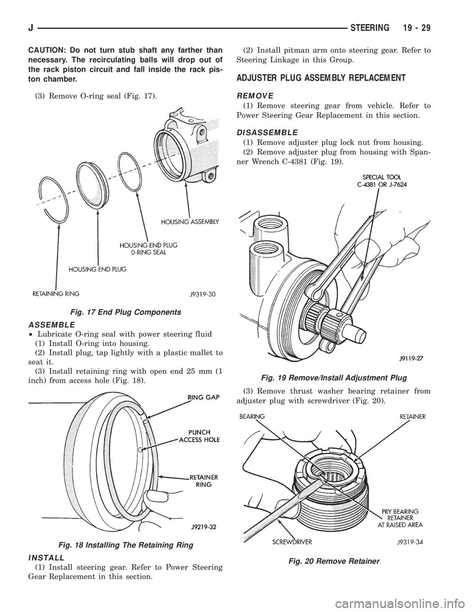
(3) Remove O-ring seal (Fig. 17).
ASSEMBLE
²Lubricate O-ring seal with power steering fluid
(1) Install O-ring into housing.
(2) Install plug, tap lightly with a plastic mallet to
seat it.
(3) Install retaining ring with open end 25 mm (1
inch) from access hole (Fig. 18).
INSTALL
(1) Install steering gear. Refer to Power Steering
Gear Replacement in this section.(2) Install pitman arm onto steering gear. Refer to
Steering Linkage in this Group.
ADJUSTER PLUG ASSEMBLY REPLACEMENT
REMOVE
(1) Remove steering gear from vehicle. Refer to
Power Steering Gear Replacement in this section.
DISASSEMBLE
(1) Remove adjuster plug lock nut from housing.
(2) Remove adjuster plug from housing with Span-
ner Wrench C-4381 (Fig. 19).
(3) Remove thrust washer bearing retainer from
adjuster plug with screwdriver (Fig. 20).
Fig. 17 End Plug Components
Fig. 18 Installing The Retaining Ring
Fig. 19 Remove/Install Adjustment Plug
Fig. 20 Remove Retainer
JSTEERING 19 - 29