1995 JEEP CHEROKEE suspension
[x] Cancel search: suspensionPage 3 of 2198
CLASSIFICATION OF LUBRICANTS
Lubricating fluids and chassis lubricants are clas-
sified according to standards recommended by the:
²Society of Automotive Engineers (SAE)
²American Petroleum Institute (API)
²National Lubricating Grease Institute (NLGI)
ENGINE OIL
API CERTIFICATION MARK
For maximum engine protection during all driving
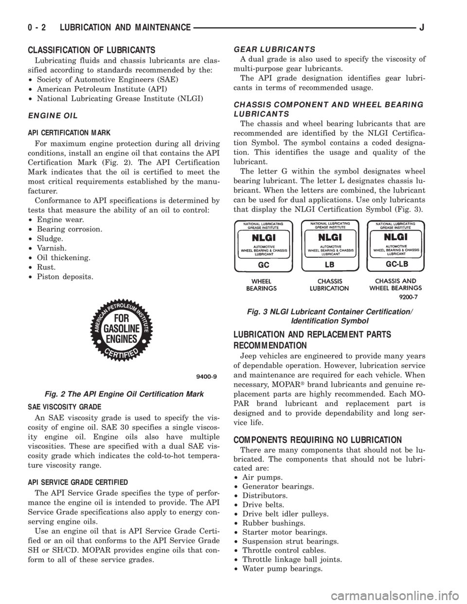
conditions, install an engine oil that contains the API
Certification Mark (Fig. 2). The API Certification
Mark indicates that the oil is certified to meet the
most critical requirements established by the manu-
facturer.
Conformance to API specifications is determined by
tests that measure the ability of an oil to control:
²Engine wear.
²Bearing corrosion.
²Sludge.
²Varnish.
²Oil thickening.
²Rust.
²Piston deposits.
SAE VISCOSITY GRADE
An SAE viscosity grade is used to specify the vis-
cosity of engine oil. SAE 30 specifies a single viscos-
ity engine oil. Engine oils also have multiple
viscosities. These are specified with a dual SAE vis-
cosity grade which indicates the cold-to-hot tempera-
ture viscosity range.
API SERVICE GRADE CERTIFIED
The API Service Grade specifies the type of perfor-
mance the engine oil is intended to provide. The API
Service Grade specifications also apply to energy con-
serving engine oils.
Use an engine oil that is API Service Grade Certi-
fied or an oil that conforms to the API Service Grade
SH or SH/CD. MOPAR provides engine oils that con-
form to all of these service grades.
GEAR LUBRICANTS
A dual grade is also used to specify the viscosity of
multi-purpose gear lubricants.
The API grade designation identifies gear lubri-
cants in terms of recommended usage.
CHASSIS COMPONENT AND WHEEL BEARING
LUBRICANTS
The chassis and wheel bearing lubricants that are
recommended are identified by the NLGI Certifica-
tion Symbol. The symbol contains a coded designa-
tion. This identifies the usage and quality of the
lubricant.
The letter G within the symbol designates wheel
bearing lubricant. The letter L designates chassis lu-
bricant. When the letters are combined, the lubricant
can be used for dual applications. Use only lubricants
that display the NLGI Certification Symbol (Fig. 3).
LUBRICATION AND REPLACEMENT PARTS
RECOMMENDATION
Jeep vehicles are engineered to provide many years
of dependable operation. However, lubrication service
and maintenance are required for each vehicle. When
necessary, MOPARtbrand lubricants and genuine re-
placement parts are highly recommended. Each MO-
PAR brand lubricant and replacement part is
designed and to provide dependability and long ser-
vice life.
COMPONENTS REQUIRING NO LUBRICATION
There are many components that should not be lu-
bricated. The components that should not be lubri-
cated are:
²Air pumps.
²Generator bearings.
²Distributors.
²Drive belts.
²Drive belt idler pulleys.
²Rubber bushings.
²Starter motor bearings.
²Suspension strut bearings.
²Throttle control cables.
²Throttle linkage ball joints.
²Water pump bearings.
Fig. 2 The API Engine Oil Certification Mark
Fig. 3 NLGI Lubricant Container Certification/
Identification Symbol
0 - 2 LUBRICATION AND MAINTENANCEJ
Page 11 of 2198
CAUTION: Do not crank starter motor on disabled
vehicle for more than 15 seconds, starter will over-
heat and could fail.
(6) Allow battery in disabled vehicle to charge to at
least 12.4 volts (75%charge) before attempting to
start engine. If engine does not start within 15 sec-
onds, stop cranking engine and allow starter to cool
(15 min.), before cranking again.
DISCONNECT CABLE CLAMPS AS FOLLOWS:
²Disconnect BLACK cable clamp from engine
ground on disabled vehicle.
²When using a Booster vehicle, disconnect BLACK
cable clamp from battery negative terminal. Discon-
nect RED cable clamp from battery positive terminal.
²Disconnect RED cable clamp from battery positive
terminal on disabled vehicle.
PORTABLE STARTING UNIT
There are many types of portable starting units
available for starting engines. Follow the manufac-
turer's instructions and observe the listed precau-
tions when involved in any engine starting
procedure.
HOISTING RECOMMENDATIONS
Refer to the Owner's Manual for emergency vehicle
lifting procedures.
FLOOR JACK
When properly positioned, a floor jack can be used
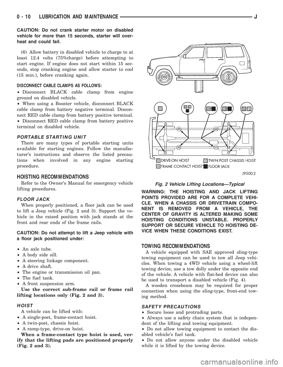
to lift a Jeep vehicle (Fig. 2 and 3). Support the ve-
hicle in the raised position with jack stands at the
front and rear ends of the frame rails.
CAUTION: Do not attempt to lift a Jeep vehicle with
a floor jack positioned under:
²An axle tube.
²A body side sill.
²A steering linkage component.
²A drive shaft.
²The engine or transmission oil pan.
²The fuel tank.
²A front suspension arm.
Use the correct sub-frame rail or frame rail
lifting locations only (Fig. 2 and 3).
HOIST
A vehicle can be lifted with:
²A single-post, frame-contact hoist.
²A twin-post, chassis hoist.
²A ramp-type, drive-on hoist.
When a frame-contact type hoist is used, ver-
ify that the lifting pads are positioned properly
(Fig. 2 and 3).WARNING: THE HOISTING AND JACK LIFTING
POINTS PROVIDED ARE FOR A COMPLETE VEHI-
CLE. WHEN A CHASSIS OR DRIVETRAIN COMPO-
NENT IS REMOVED FROM A VEHICLE, THE
CENTER OF GRAVITY IS ALTERED MAKING SOME
HOISTING CONDITIONS UNSTABLE. PROPERLY
SUPPORT OR SECURE VEHICLE TO HOISTING DE-
VICE WHEN THESE CONDITIONS EXIST.
TOWING RECOMMENDATIONS
A vehicle equipped with SAE approved sling-type
towing equipment can be used to tow all Jeep vehi-
cles. When towing a 4WD vehicle using a wheel-lift
towing device, use a tow dolly under the opposite end
of the vehicle. A vehicle with flat-bed device can also
be used to transport a disabled vehicle (Fig. 4).
A wooden crossbeam may be required for proper
connection when using the sling-type, front-end tow-
ing method.
SAFETY PRECAUTIONS
²Secure loose and protruding parts.
²Always use a safety chain system that is indepen-
dent of the lifting and towing equipment.
²Do not allow towing equipment to contact the dis-
abled vehicle's fuel tank.
²Do not allow anyone under the disabled vehicle
while it is lifted by the towing device.
Fig. 2 Vehicle Lifting LocationsÐTypical
0 - 10 LUBRICATION AND MAINTENANCEJ
Page 29 of 2198

CHASSIS AND BODY COMPONENTS
INDEX
page page
Body Components........................ 32
Chassis Component and Wheel Bearing
Lubricants............................. 28
Front Wheel Bearings...................... 28
Headlamps.............................. 33
Manual Steering Gear...................... 30Power Brake System....................... 30
Power Steering System..................... 29
Speedometer Cable....................... 33
Steering Linkage.......................... 28
Tires................................... 32
CHASSIS COMPONENT AND WHEEL BEARING
LUBRICANTS
The chassis component and wheel bearing lubri-
cants that are recommended for Jeep vehicles are
identified by the NLGI Certification Symbol (Fig. 1).
The symbol contains a coded designation that identi-
fies the usage and quality of the lubricant.
The letterGdesignates wheel bearing lubricant.
LetterLdesignates chassis lubricant. When the let-
ters are combined the lubricant can be used for dual
applications. The suffix lettersCandBdesignate the
level of the lubricant for the application. The letterC
represents level available for wheel bearing lubricant
(G) and the letterBrepresents level available for
chassis lubricant (L).
STEERING LINKAGE
The steering linkage (Fig. 2) should be lubricated
and inspected at the intervals described in the Main-
tenance Schedules section of this Group. Refer to
Group 2, Front Suspension and Axles for proper ser-
vice procedures.
LUBRICANT SPECIFICATION
Use Mopar, Multi-purpose Grease or NLGI GC-LB
lubricant equivalent to lubricate the steering linkage.
INSPECTION
(1) Inspect the steering linkage. Examine the tie
rods and the drag link for bending, and the ball
studs for looseness and excessive wear.(2) Replace, as necessary, all torn/ruptured ball-
stud seals and damaged/defective steering linkage
components.
CAUTION: Use care to prevent lubricant from con-
tacting the brake rotors.
FRONT WHEEL BEARINGS
Some 2WD XJ vehicles are equipped with service-
able front wheel bearings. XJ 4WD vehicles have
semi-floating axle shafts and axle shaft bearings that
are lubricated via differential lube oil.
RECOMMENDED MAINTENANCEÐ2WD XJ
VEHICLES
If equipped, the serviceable front wheel bearings
should be lubricated (re-packed) at the same time as
front brake pad/caliper service is conducted.
LUBRICANT SPECIFICATION
Wheel bearings should be lubricated with a lubri-
cant that is identified as NLGI GC-LB lubricant.
INSPECTION/LUBRICATION
(1) Remove the wheel/tire and the disc brake cali-
per.Do not disconnect the caliper brake fluid
Fig. 1 NLGI Lubricant Container Certification/
Identification Symbol
Fig. 2 Steering Components (XJ)ÐTypical
0 - 28 LUBRICATION AND MAINTENANCEJ
Page 36 of 2198
FRONT SUSPENSION AND AXLE
CONTENTS
page page
AXLE NOISE/VIBRATION DIAGNOSIS........ 18
AXLE SPECIFICATIONS................... 49
FRONT WHEEL ALIGNMENT................ 5
GENERAL INFORMATION.................. 1MODEL 30 AXLE AND TUBE AXLE (2WD).... 22
TORQUE SPECIFICATIONS................ 49
XJ FRONT SUSPENSION.................. 11
YJ FRONT SUSPENSION.................. 15
GENERAL INFORMATION
FRONT SUSPENSION
XJ VEHICLES
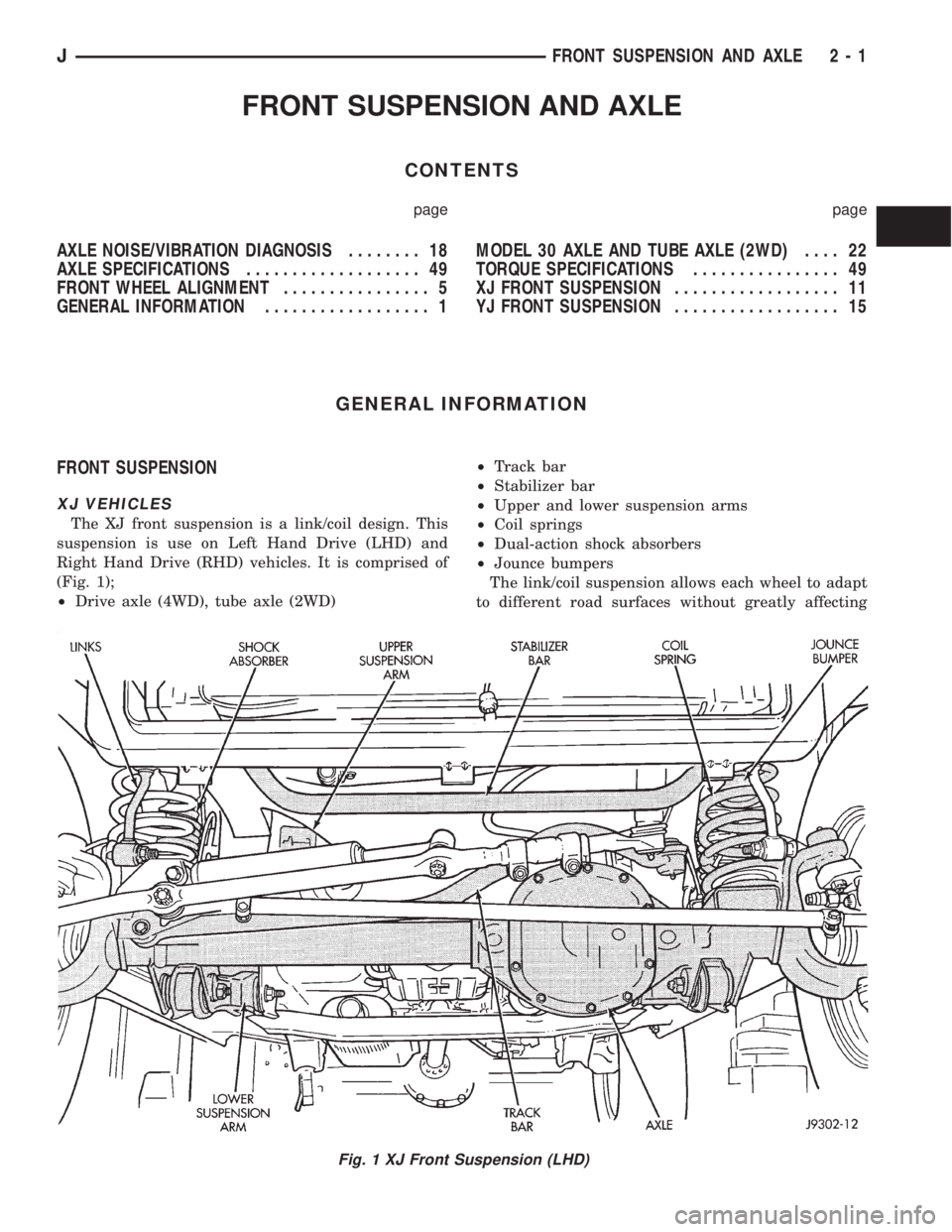
The XJ front suspension is a link/coil design. This
suspension is use on Left Hand Drive (LHD) and
Right Hand Drive (RHD) vehicles. It is comprised of
(Fig. 1);
²Drive axle (4WD), tube axle (2WD)²Track bar
²Stabilizer bar
²Upper and lower suspension arms
²Coil springs
²Dual-action shock absorbers
²Jounce bumpers
The link/coil suspension allows each wheel to adapt
to different road surfaces without greatly affecting
Fig. 1 XJ Front Suspension (LHD)
JFRONT SUSPENSION AND AXLE 2 - 1
Page 37 of 2198
the opposite wheel. Wheels are attached to a hub/
bearings which bolts to the knuckles. The hub/bear-
ing is not serviceable and is replaced as a unit.
Steering knuckles pivot on replaceable ball studs at-
tached to the axle tube yokes.
The upper and lower suspension arms are different
lengths, with bushings at both ends. They bolt the
axle assembly to the body. The lower arms uses
shims at the body mount to allow for adjustment of
caster and drive shaft pinion angle. The suspension
arm travel is limited through the use of jounce
bumpers in compression and shocks absorbers in re-
bound.
Suspension components which use rubber bushings
should be tightened at vehicle ride height. This will
prevent premature failure of the bushing and main-
tain ride comfort. Bushings must never be lubricated.
The coil springs control ride quality and maintain
proper ride height. The coil springs mount up in the
fender shield which is part of the unitized body
bracket. A rubber isolator is located between the top
of the spring and the frame. The bottom of the spring
seats on a axle pad and is retained with a clip.
The shock absorbers dampen jounce and rebound of
the vehicle over various road conditions. The top of
the shock absorbers are bolted to the body. The bot-
tom of the shocks are bolted to the axle spring
bracket.
The stabilizer bar is used to minimize vehicle body
roll during turns. The spring steel bar helps to con-
trol the vehicle body in relationship to the suspen-
sion. The bar extends across the front underside of
the chassis and connects to the body rails. Links are
connected from the bar to the axle brackets. Stabi-
lizer bar mounts are isolated by rubber bushings.
The track bar is used to minimize front axle side-
to-side movement. The bar is attached to a frame rail
bracket with a ball stud and isolated with a bushing
at the axle bracket.
TUBE AXLE (2WD VEHICLES)
The front axle used on two-wheel drive vehicles is
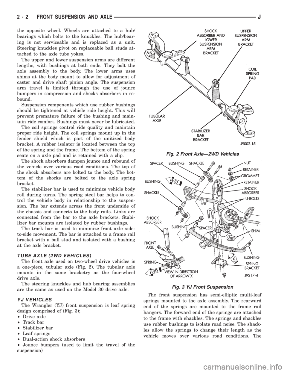
a one-piece, tubular axle (Fig. 2). The tubular axle
mounts in the same bracketry as the four-wheel
drive axle.
The steering knuckles and hub bearing assemblies
are the same as used on the Model 30 drive axle.
YJ VEHICLES
The Wrangler (YJ) front suspension is leaf spring
design comprised of (Fig. 3);
²Drive axle
²Track bar
²Stabilizer bar
²Leaf springs
²Dual-action shock absorbers
²Jounce bumpers (used to limit the travel of the
suspension)The front suspension has semi-elliptic multi-leaf
springs mounted to the axle assembly. The rearward
end of the springs are mounted to the frame rail
hangers. The forward end of the springs are attached
to the frame with shackles. The springs and shackles
use rubber bushings to isolate road noise. The shack-
les allow the springs to change their length as the
vehicle moves over various road conditions. The
Fig. 2 Front AxleÐ2WD Vehicles
Fig. 3 YJ Front Suspension
2 - 2 FRONT SUSPENSION AND AXLEJ
Page 38 of 2198
spring and axle travel (jounce or rebound) is limited
through use of rubber bumpers mounted on the
frame.
Suspension components which use rubber bushings
should be tightened at vehicle ride height. This will
prevent premature failure of the bushing and main-
tain ride comfort. The bushings should never be lu-
bricated.
The shocks absorbers dampen jounce and rebound
of the vehicle over various road conditions. The top of
the shock absorbers bolt to the frame. The bottom of
the shocks bolt to the axle brackets.
The stabilizer bar is used to minimize vehicle front
sway during turns. The spring steel bar helps control
vehicle body in relationship to the suspension move-
ment. The bar extends across the front underside of
the chassis and connects to the frame rails. Links
connect the bar to the axle brackets. Stabilizer bar
mounts are isolated by rubber bushings.
The track bar is used to minimize front axle side-
to-side movement. The track bar is attached to a
frame rail bracket and axle bracket. The bar uses
bushings at both ends.
FRONT DRIVE AXLE
It is not necessary to remove the complete axle
from the vehicle for routine differential service. If the
differential housing or axle shaft tubes are damaged,
the complete axle assembly can be removed and ser-
viced.
For complete drive axle assembly removal and in-
stallation refer to Drive Axle Assembly Replacement
in this Group.
The removable cover provides for servicing without
removing axle from vehicle.
The integral type housing, hypoid gear design has
the centerline of the pinion set above the centerline
of the ring gear.
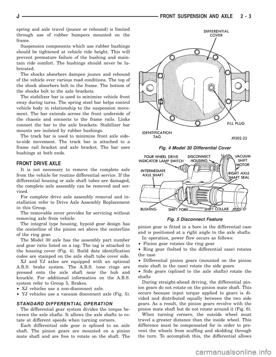
The Model 30 axle has the assembly part number
and gear ratio listed on a tag. The tag is attached to
the housing cover (Fig. 4). Build date identification
codes are stamped on the axle shaft tube cover side.
XJ and YJ axles are equipped with an optional
A.B.S. brake system. The A.B.S. tone rings are
pressed onto the axle shaft near the hub and
knuckle. For additional information on the A.B.S.
system refer to Group 5, Brakes.
²XJ vehicles use a non-disconnect axle.
²YJ vehicles use a vacuum disconnect axle (Fig. 5).
STANDARD DIFFERENTIAL OPERATION
The differential gear system divides the torque be-
tween the axle shafts. It allows the axle shafts to ro-
tate at different speeds when turning corners.
Each differential side gear is splined to an axle
shaft. The pinion gears are mounted on a pinion
mate shaft and are free to rotate on the shaft. Thepinion gear is fitted in a bore in the differential case
and is positioned at a right angle to the axle shafts.
In operation, power flow occurs as follows:
²Pinion gear rotates the ring gear
²Ring gear (bolted to the differential case) rotates
the case
²Differential pinion gears (mounted on the pinion
mate shaft in the case) rotate the side gears
²Side gears (splined to the axle shafts) rotate the
shafts
During straight-ahead driving, the differential pin-
ion gears do not rotate on the pinion mate shaft. This
occurs because input torque applied to gears is di-
vided and distributed equally between the two side
gears. As a result, the pinion gears revolve with the
pinion mate shaft but do not rotate around it (Fig. 6).
When turning corners, the outside wheel must
travel a greater distance than the inside wheel. This
difference must be compensated for in order to pre-
vent the wheels from scuffing and skidding through
the turn. To accomplish this, the differential allows
Fig. 4 Model 30 Differential Cover
Fig. 5 Disconnect Feature
JFRONT SUSPENSION AND AXLE 2 - 3
Page 39 of 2198
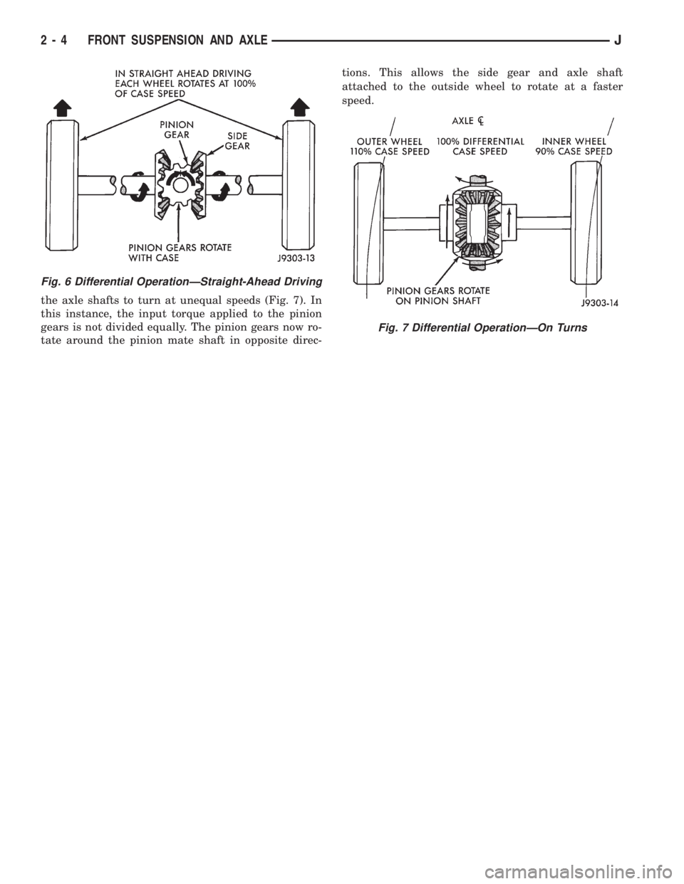
the axle shafts to turn at unequal speeds (Fig. 7). In
this instance, the input torque applied to the pinion
gears is not divided equally. The pinion gears now ro-
tate around the pinion mate shaft in opposite direc-tions. This allows the side gear and axle shaft
attached to the outside wheel to rotate at a faster
speed.
Fig. 6 Differential OperationÐStraight-Ahead Driving
Fig. 7 Differential OperationÐOn Turns
2 - 4 FRONT SUSPENSION AND AXLEJ
Page 40 of 2198
FRONT WHEEL ALIGNMENT
INDEX
page page
Alignment Measurements and Adjustments....... 8
General Information........................ 5Pre-Alignment Inspection.................... 6
GENERAL INFORMATION
Front wheel alignment involves the correct posi-
tioning of the wheels in relation to the vehicle. The
positioning is accomplished through suspension and
steering linkage adjustments. An alignment is con-
sidered essential for efficient steering, good direc-
tional stability and to maximize tire wear. The most
important measurements of front end alignment are
caster, camber and toe position.
Routine inspection of the front suspension
and steering components is a good preventative
maintenance practice. Inspection also helps to
ensure safe operation of the vehicle.
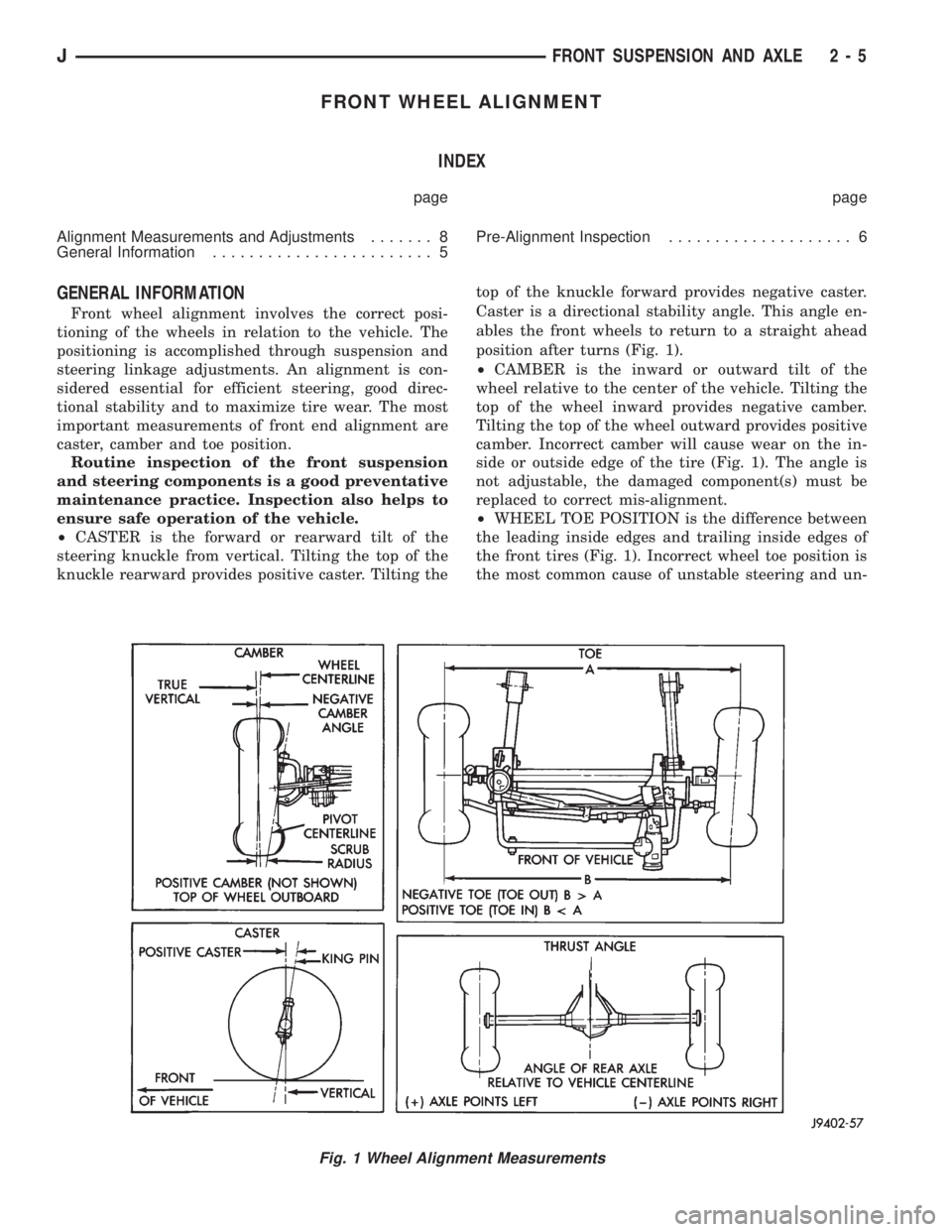
²CASTER is the forward or rearward tilt of the
steering knuckle from vertical. Tilting the top of the
knuckle rearward provides positive caster. Tilting thetop of the knuckle forward provides negative caster.
Caster is a directional stability angle. This angle en-
ables the front wheels to return to a straight ahead
position after turns (Fig. 1).
²CAMBER is the inward or outward tilt of the
wheel relative to the center of the vehicle. Tilting the
top of the wheel inward provides negative camber.
Tilting the top of the wheel outward provides positive
camber. Incorrect camber will cause wear on the in-
side or outside edge of the tire (Fig. 1). The angle is
not adjustable, the damaged component(s) must be
replaced to correct mis-alignment.
²WHEEL TOE POSITION is the difference between
the leading inside edges and trailing inside edges of
the front tires (Fig. 1). Incorrect wheel toe position is
the most common cause of unstable steering and un-
Fig. 1 Wheel Alignment Measurements
JFRONT SUSPENSION AND AXLE 2 - 5