1995 JEEP CHEROKEE fan blade
[x] Cancel search: fan bladePage 24 of 2198

If the transmission is warm, lube oil could
drip out of the fill hole. This is acceptable but
the lube oil should not gush out of the fill hole.
(2) If not acceptable, raise the lube oil level to the
bottom edge of the transmission fill hole.
Add lube oil in small amounts to raise the
level.
(3) Install the fill-hole plug in the transmission.
Tighten the plug with 37 Nzm (27 ft. lbs.) torque.
LUBE OIL CHANGE
When it becomes necessary to change manual
transmission lube oil, use the following procedure.
(1) Raise and support the vehicle.
(2) Remove the fill-hole plug from the transmis-
sion.
(3) Place a container to collect the lube oil under
the transmission drain-hole plug.
(4) Remove the drain-hole plug and drain the lube
oil from the transmission into the container.
Care should be exercised when disposing
used lube oil after it has been drained from a
transmission.
(5) Install the drain-hole plug in the transmission.
Tighten the plug with 37 Nzm (27 ft. lbs.) torque.
(6) Fill the transmission until the lube oil begins to
drip out of the fill hole.
(7) Install the fill-hole plug in the transmission.
Tighten the plug with 37 Nzm (27 ft. lbs.) torque.
(8) Remove the support and lower the vehicle.
AUTOMATIC TRANSMISSION
The automatic transmission fluid should be
changed and bands adjusted at the intervals de-
scribed in the Maintenance Schedules section of this
Group. The automatic transmission should be in-
spected for fluid leaks and proper fluid level whenother under hood service is performed. Refer to
Group 21, Transmission for proper service proce-
dures.
CAUTION: To minimize fluid contamination, verify
that dipstick is seated in the fill tube after fluid level
reading is taken.
TO INSPECT THE TRANSMISSION FLUID
LEVEL
WARNING: USE EXTREME CAUTION WHEN THE
ENGINE IS OPERATING. DO NOT PUT YOUR
HANDS NEAR THE DRIVE BELT, PULLEYS OR FAN
BLADE. DO NOT STAND IN A DIRECT LINE WITH
THE FAN BLADE.
(1) Be sure transmission fluid is at normal operat-
ing temperature. Normal operating temperature is
reached after approximately 15 miles (25km) of oper-
ation.
(2) Position the vehicle on a level surface. This is
important for an accurate fluid level check.
(3) While sitting in driver seat, apply brakes and
place gear selector in each position, then move the
selector to:
²XJ vehicles-P (Park).
²YJ vehicles-N (Neutral).
(4) Apply parking brake.
(5) Raise hood and wipe off dipstick handle to pre-
vent dirt from entering fill tube. Then remove trans-
mission fluid level indicator (dipstick) and wipe clean
with a wiping cloth.
(6) Install dipstick and verify it is seated in fill
hole or tube.
(7) Remove dipstick, with handle above tip, take
fluid level reading. If the vehicle has been driven for
at least 15 minutes before inspecting fluid level,
transmission can be considered hot and reading
should be in the OK area. If vehicle has run for less
than 15 minutes and more than 60 seconds transmis-
sion can be considered warm and reading should be
above MIN mark. Add fluid only if level is below
MIN mark on dipstick when transmission is warm
(Fig. 4).
CAUTION: Do not overfill automatic transmission,
leakage or damage can result.
AUTOMATIC TRANSMISSION FLUID
SPECIFICATION
When it becomes necessary to add fluid or when
the ATF is replaced, use:
²MOPAR Dexron IIE/Mercon ATFonlyfor AW-4
automatic transmissions (XJ vehicles).
²MOPAR ATF PLUS type 7176 (YJ vehicles).
Fig. 3 Manual Transmission Fill- & Drain-Hole
PlugsÐTypical
JLUBRICATION AND MAINTENANCE 0 - 23
Page 238 of 2198
SERVICE PROCEDURES
INDEX
page page
Auxiliary Electric Cooling FanÐXJ Models with 4.0L
6-Cylinder Engine....................... 35
Coolant................................. 20
Coolant Reserve/Overflow System............. 24
Cooling System Cleaning/Reverse Flushing...... 22
Cooling System Fans...................... 32
Cooling System Hoses..................... 32
Draining Cooling System.................... 21
Radiator Pressure Cap..................... 25
Radiators............................... 26Refilling Cooling System.................... 21
Testing Cooling System for Leaks............. 22
Thermostat.............................. 17
Transmission Oil Coolers.................... 36
Viscous Fan Drive......................... 34
Water Pump Tests......................... 13
Water PumpsÐGeneral Information............ 13
Water PumpsÐRemoval/Installation........... 14
WATER PUMPSÐGENERAL INFORMATION
A centrifugal water pump circulates coolant
through the water jackets, passages, intake manifold,
radiator core, cooling system hoses and heater core.
The pump is driven from the engine crankshaft by a
drive belt on all engines.
The water pump impeller is pressed onto the rear
of a shaft that rotates in bearings pressed into the
housing. The housing has a small hole to allow seep-
age to escape. The water pump seals are lubricated
by the antifreeze in the coolant mixture. No addi-
tional lubrication is necessary.
CAUTION: All engines are equipped with a reverse
(counter-clockwise) rotating water pump and vis-
cous fan drive assembly. REVERSE is stamped or
imprinted on the cover of the viscous fan drive and
inner side of the fan. The letter R is stamped into
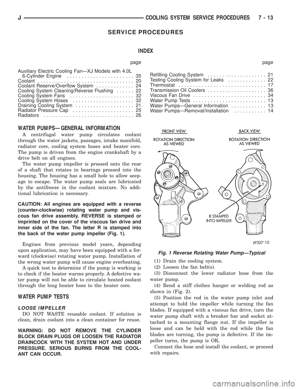
the back of the water pump impeller (Fig. 1).
Engines from previous model years, depending
upon application, may have been equipped with a for-
ward (clockwise) rotating water pump. Installation of
the wrong water pump will cause engine overheating.
A quick test to determine if the pump is working is
to check if the heater warms properly. A defective wa-
ter pump will not be able to circulate heated coolant
through the long heater hose to the heater core.
WATER PUMP TESTS
LOOSE IMPELLER
DO NOT WASTE reusable coolant. If solution is
clean, drain coolant into a clean container for reuse.
WARNING: DO NOT REMOVE THE CYLINDER
BLOCK DRAIN PLUGS OR LOOSEN THE RADIATOR
DRAINCOCK WITH THE SYSTEM HOT AND UNDER
PRESSURE. SERIOUS BURNS FROM THE COOL-
ANT CAN OCCUR.(1) Drain the cooling system.
(2) Loosen the fan belt(s).
(3) Disconnect the lower radiator hose from the
water pump.
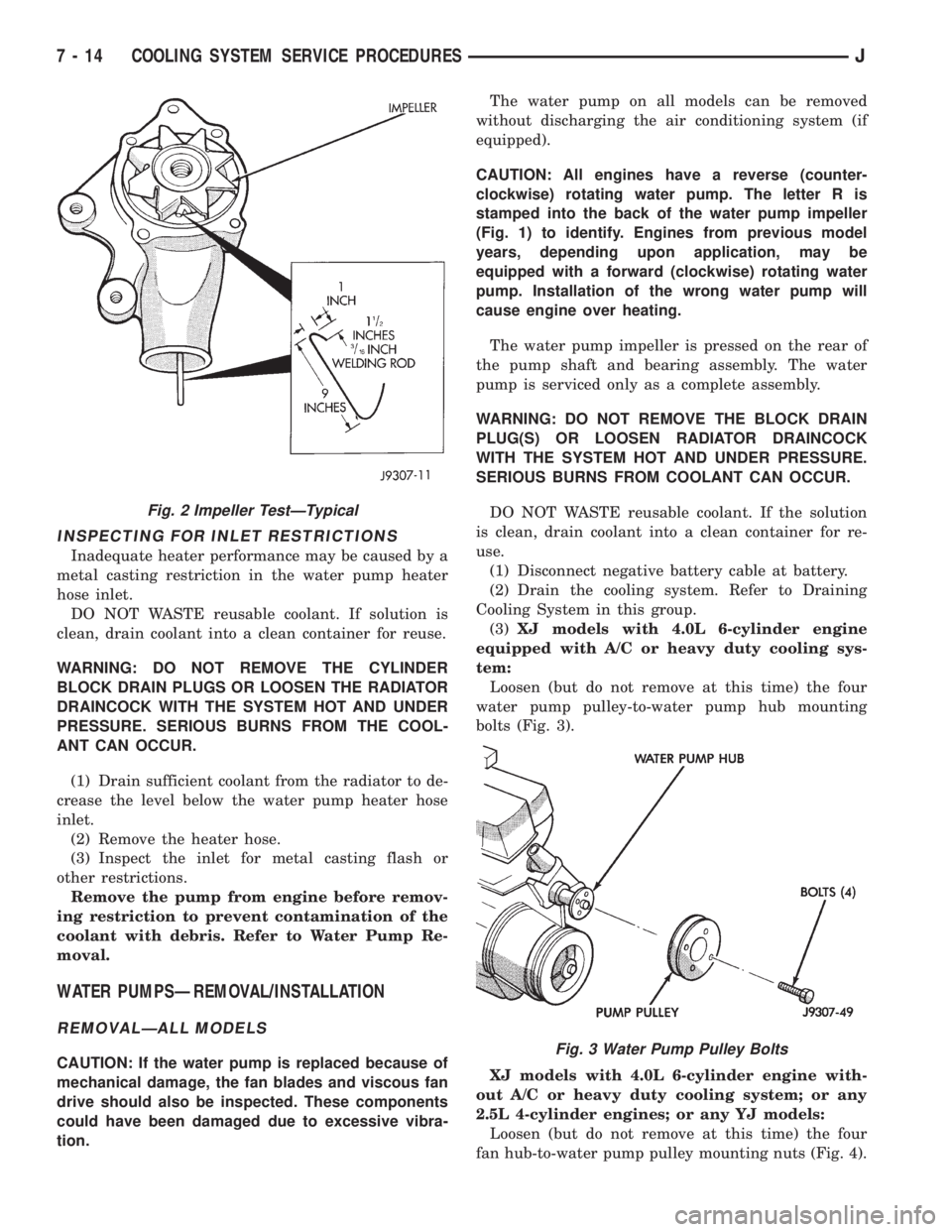
(4) Bend a stiff clothes hanger or welding rod as
shown in (Fig. 2).
(5) Position the rod in the water pump inlet and
attempt to hold the impeller while turning the fan
blades. If equipped with a viscous fan drive, turn the
water pump shaft with a breaker bar and socket at-
tached to a mounting flange nut. If the impeller is
loose and can be held with the rod while the fan
blades are turning, the pump is defective. If the im-
peller turns, the pump is OK.
Connect the hose and install the coolant, or proceed
with repairs.
Fig. 1 Reverse Rotating Water PumpÐTypical
JCOOLING SYSTEM SERVICE PROCEDURES 7 - 13
Page 239 of 2198
INSPECTING FOR INLET RESTRICTIONS
Inadequate heater performance may be caused by a
metal casting restriction in the water pump heater
hose inlet.
DO NOT WASTE reusable coolant. If solution is
clean, drain coolant into a clean container for reuse.
WARNING: DO NOT REMOVE THE CYLINDER
BLOCK DRAIN PLUGS OR LOOSEN THE RADIATOR
DRAINCOCK WITH THE SYSTEM HOT AND UNDER
PRESSURE. SERIOUS BURNS FROM THE COOL-
ANT CAN OCCUR.
(1) Drain sufficient coolant from the radiator to de-
crease the level below the water pump heater hose
inlet.
(2) Remove the heater hose.
(3) Inspect the inlet for metal casting flash or
other restrictions.
Remove the pump from engine before remov-
ing restriction to prevent contamination of the
coolant with debris. Refer to Water Pump Re-
moval.
WATER PUMPSÐREMOVAL/INSTALLATION
REMOVALÐALL MODELS
CAUTION: If the water pump is replaced because of
mechanical damage, the fan blades and viscous fan
drive should also be inspected. These components
could have been damaged due to excessive vibra-
tion.The water pump on all models can be removed
without discharging the air conditioning system (if
equipped).
CAUTION: All engines have a reverse (counter-
clockwise) rotating water pump. The letter R is
stamped into the back of the water pump impeller
(Fig. 1) to identify. Engines from previous model
years, depending upon application, may be
equipped with a forward (clockwise) rotating water
pump. Installation of the wrong water pump will
cause engine over heating.
The water pump impeller is pressed on the rear of
the pump shaft and bearing assembly. The water
pump is serviced only as a complete assembly.
WARNING: DO NOT REMOVE THE BLOCK DRAIN
PLUG(S) OR LOOSEN RADIATOR DRAINCOCK
WITH THE SYSTEM HOT AND UNDER PRESSURE.
SERIOUS BURNS FROM COOLANT CAN OCCUR.
DO NOT WASTE reusable coolant. If the solution
is clean, drain coolant into a clean container for re-
use.
(1) Disconnect negative battery cable at battery.
(2) Drain the cooling system. Refer to Draining
Cooling System in this group.
(3)XJ models with 4.0L 6-cylinder engine
equipped with A/C or heavy duty cooling sys-
tem:
Loosen (but do not remove at this time) the four
water pump pulley-to-water pump hub mounting
bolts (Fig. 3).
XJ models with 4.0L 6-cylinder engine with-
out A/C or heavy duty cooling system; or any
2.5L 4-cylinder engines; or any YJ models:
Loosen (but do not remove at this time) the four
fan hub-to-water pump pulley mounting nuts (Fig. 4).
Fig. 2 Impeller TestÐTypical
Fig. 3 Water Pump Pulley Bolts
7 - 14 COOLING SYSTEM SERVICE PROCEDURESJ
Page 241 of 2198
(11) Remove idler pulley mounting bolt and remove
idler pulley. This must be done to gain clearance for
the water pump mounted heater hose fitting when
water pump is being removed. Note position of pulley
spacers after removal.
WARNING: CONSTANT TENSION HOSE CLAMPS
ARE USED ON MOST COOLING SYSTEM HOSES.
WHEN REMOVING OR INSTALLING, USE ONLY
TOOLS DESIGNED FOR SERVICING THIS TYPE OF
CLAMP, SUCH AS SPECIAL CLAMP TOOL (NUMBER
6094) (FIG. 8). SNAP-ON CLAMP TOOL (NUMBER
HPC-20) MAY BE USED FOR LARGER CLAMPS. AL-
WAYS WEAR SAFETY GLASSES WHEN SERVICING
CONSTANT TENSION CLAMPS.
CAUTION: A number or letter is stamped into the
tongue of constant tension clamps (Fig. 9). If re-
placement is necessary, use only an original equip-
ment clamp with matching number or letter.
(12) Remove lower radiator hose from water pump.
Remove heater hose from water pump fitting.
(13) Remove four nuts or bolts (refer to the previ-
ous step #3).
(14) Remove the fan blade assembly and pulley (if
fan is installed at pump), or remove the pulley from
the vehicle.
After removing fan blade/viscous fan drive assem-
bly,do notplace thermal viscous fan drive in hori-
zontal position. If stored horizontally, silicone fluid in
viscous fan drive could drain into its bearing assem-
bly and contaminate lubricant.
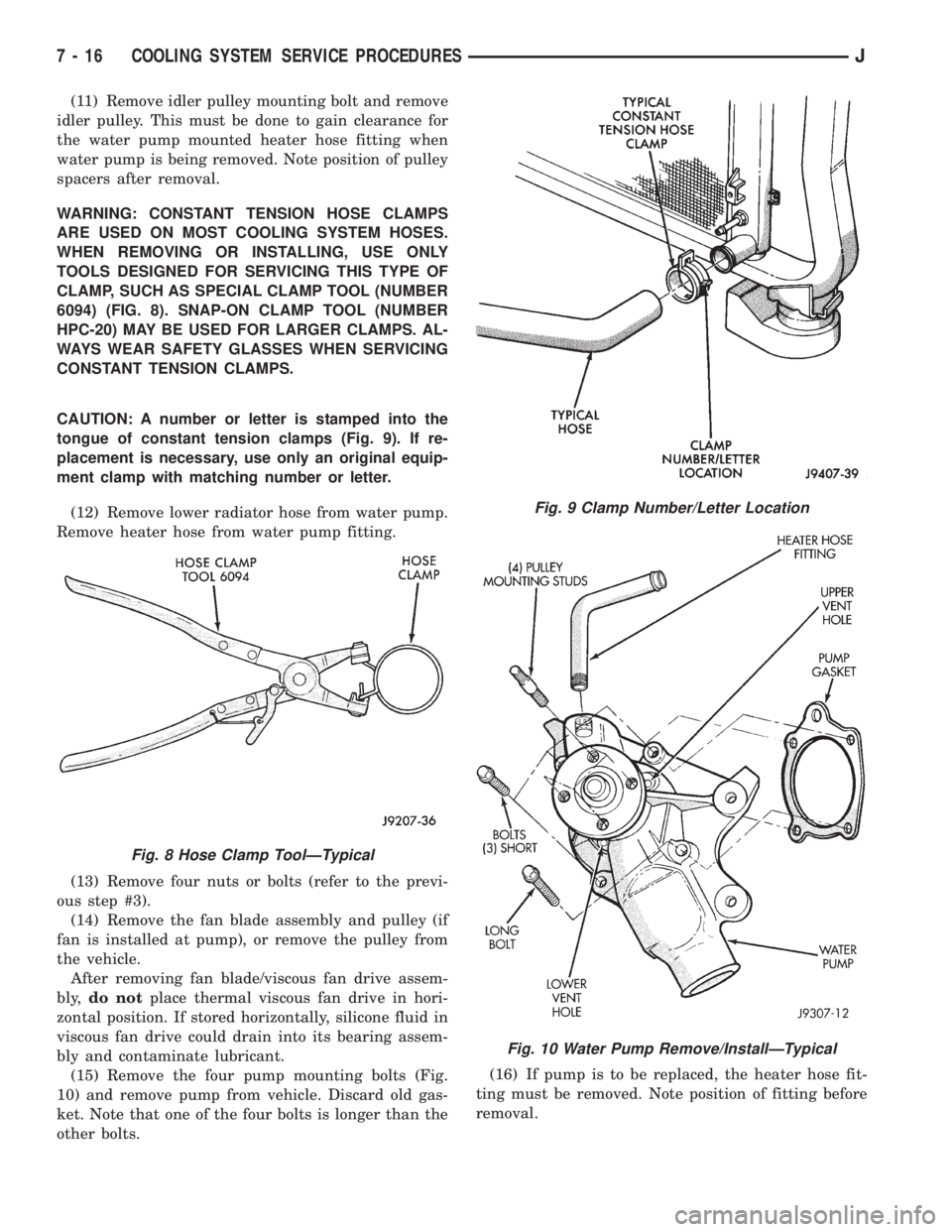
(15) Remove the four pump mounting bolts (Fig.
10) and remove pump from vehicle. Discard old gas-
ket. Note that one of the four bolts is longer than the
other bolts.(16) If pump is to be replaced, the heater hose fit-
ting must be removed. Note position of fitting before
removal.
Fig. 8 Hose Clamp ToolÐTypical
Fig. 9 Clamp Number/Letter Location
Fig. 10 Water Pump Remove/InstallÐTypical
7 - 16 COOLING SYSTEM SERVICE PROCEDURESJ
Page 256 of 2198
WAYS WEAR SAFETY GLASSES WHEN SERVICING
CONSTANT TENSION CLAMPS.
CAUTION: A number or letter is stamped into the
tongue of constant tension clamps (Fig. 28). If re-
placement is necessary, use only an original equip-
ment clamp with matching number or letter.
REMOVAL
(1) Disconnect negative battery cable at battery.
(2) Observe the previousWARNINGS.Remove the
radiator cap.
(3) Position drain pan under draincock. Open radi-
ator draincock and drain radiator.
(4) Remove radiator upper and lower hose clamps
(Figs 27 and 28). Remove radiator hoses.
(5) Disconnect coolant reserve/overflow tank hose
from radiator.
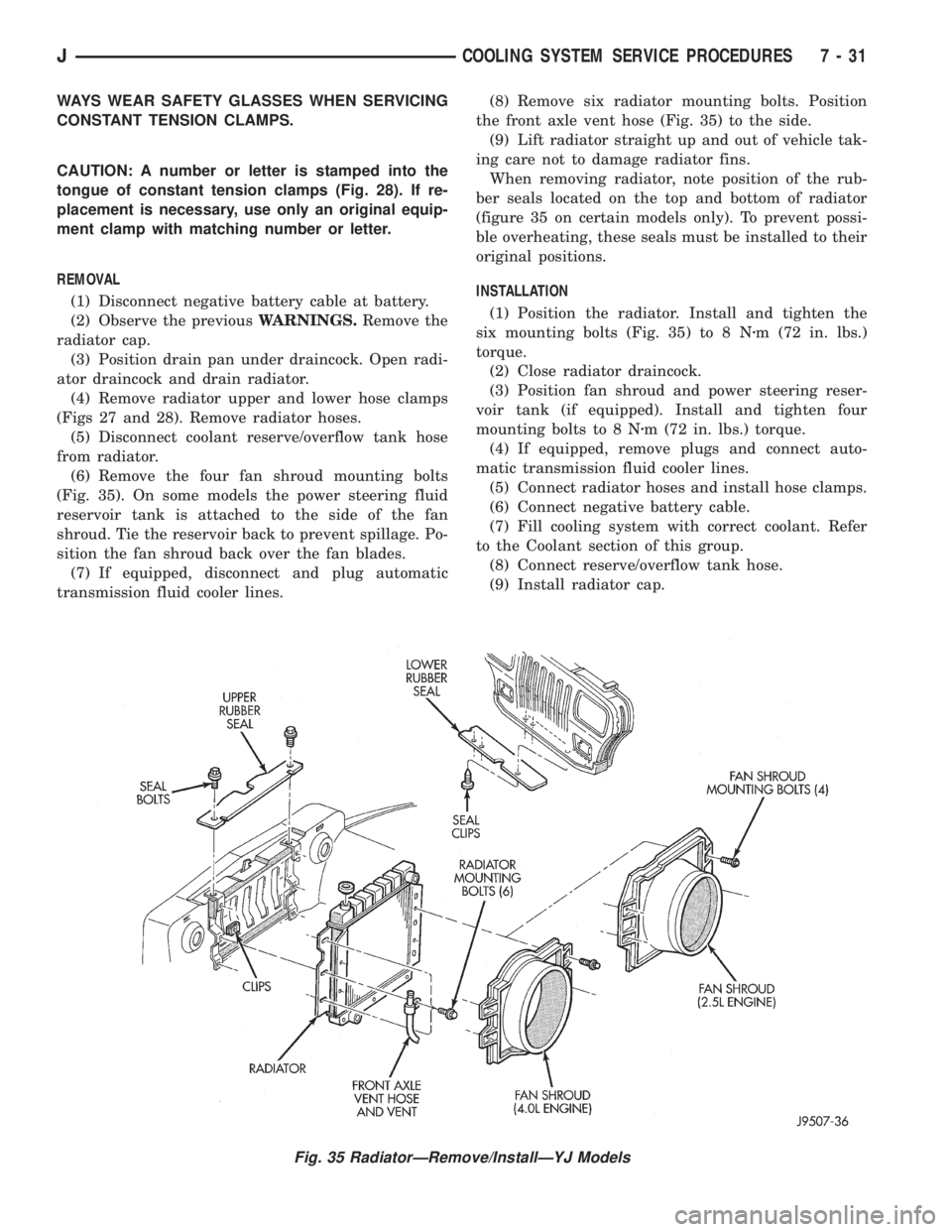
(6) Remove the four fan shroud mounting bolts
(Fig. 35). On some models the power steering fluid
reservoir tank is attached to the side of the fan
shroud. Tie the reservoir back to prevent spillage. Po-
sition the fan shroud back over the fan blades.
(7) If equipped, disconnect and plug automatic
transmission fluid cooler lines.(8) Remove six radiator mounting bolts. Position
the front axle vent hose (Fig. 35) to the side.
(9) Lift radiator straight up and out of vehicle tak-
ing care not to damage radiator fins.
When removing radiator, note position of the rub-
ber seals located on the top and bottom of radiator
(figure 35 on certain models only). To prevent possi-
ble overheating, these seals must be installed to their
original positions.
INSTALLATION
(1) Position the radiator. Install and tighten the
six mounting bolts (Fig. 35) to 8 Nzm (72 in. lbs.)
torque.
(2) Close radiator draincock.
(3) Position fan shroud and power steering reser-
voir tank (if equipped). Install and tighten four
mounting bolts to 8 Nzm (72 in. lbs.) torque.
(4) If equipped, remove plugs and connect auto-
matic transmission fluid cooler lines.
(5) Connect radiator hoses and install hose clamps.
(6) Connect negative battery cable.
(7) Fill cooling system with correct coolant. Refer
to the Coolant section of this group.
(8) Connect reserve/overflow tank hose.
(9) Install radiator cap.
Fig. 35 RadiatorÐRemove/InstallÐYJ Models
JCOOLING SYSTEM SERVICE PROCEDURES 7 - 31
Page 257 of 2198
(10) Check and adjust automatic transmission
fluid level (if equipped).
COOLING SYSTEM HOSES
Rubber hoses route coolant to and from the radia-
tor, intake manifold and heater core. All XJ models
equipped with air conditioning have a coolant control
valve. This is located in-line with the heater core in-
let and outlet hoses. It controls coolant flow to the
heater core when the air conditioning system is in
operation.
Radiator lower hoses are spring-reinforced to pre-
vent collapse from water pump suction at moderate
and high engine speeds.
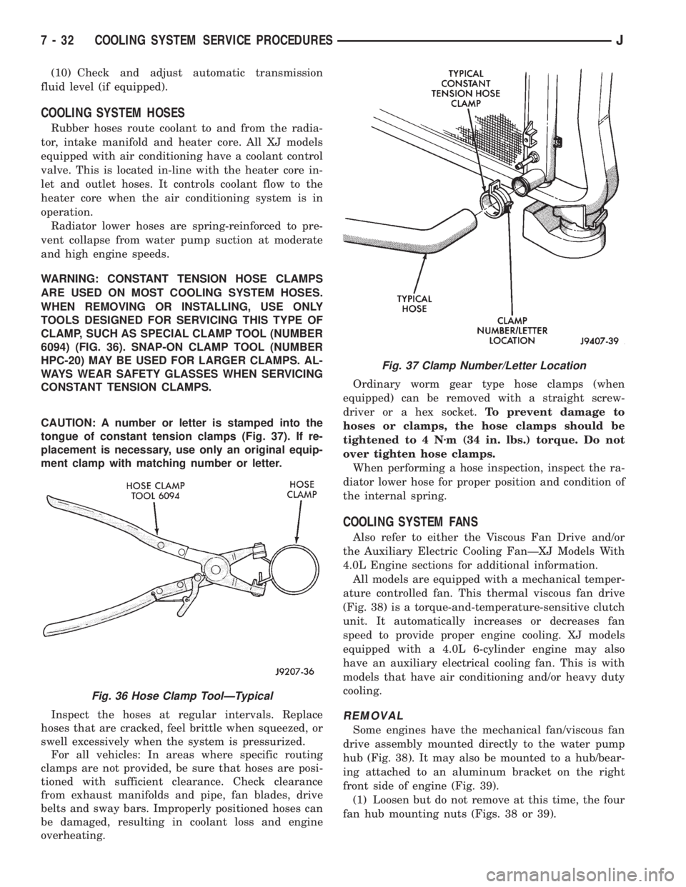
WARNING: CONSTANT TENSION HOSE CLAMPS
ARE USED ON MOST COOLING SYSTEM HOSES.
WHEN REMOVING OR INSTALLING, USE ONLY
TOOLS DESIGNED FOR SERVICING THIS TYPE OF
CLAMP, SUCH AS SPECIAL CLAMP TOOL (NUMBER
6094) (FIG. 36). SNAP-ON CLAMP TOOL (NUMBER
HPC-20) MAY BE USED FOR LARGER CLAMPS. AL-
WAYS WEAR SAFETY GLASSES WHEN SERVICING
CONSTANT TENSION CLAMPS.
CAUTION: A number or letter is stamped into the
tongue of constant tension clamps (Fig. 37). If re-
placement is necessary, use only an original equip-
ment clamp with matching number or letter.
Inspect the hoses at regular intervals. Replace
hoses that are cracked, feel brittle when squeezed, or
swell excessively when the system is pressurized.
For all vehicles: In areas where specific routing
clamps are not provided, be sure that hoses are posi-
tioned with sufficient clearance. Check clearance
from exhaust manifolds and pipe, fan blades, drive
belts and sway bars. Improperly positioned hoses can
be damaged, resulting in coolant loss and engine
overheating.Ordinary worm gear type hose clamps (when
equipped) can be removed with a straight screw-
driver or a hex socket.To prevent damage to
hoses or clamps, the hose clamps should be
tightened to 4 Nzm (34 in. lbs.) torque. Do not
over tighten hose clamps.
When performing a hose inspection, inspect the ra-
diator lower hose for proper position and condition of
the internal spring.
COOLING SYSTEM FANS
Also refer to either the Viscous Fan Drive and/or
the Auxiliary Electric Cooling FanÐXJ Models With
4.0L Engine sections for additional information.
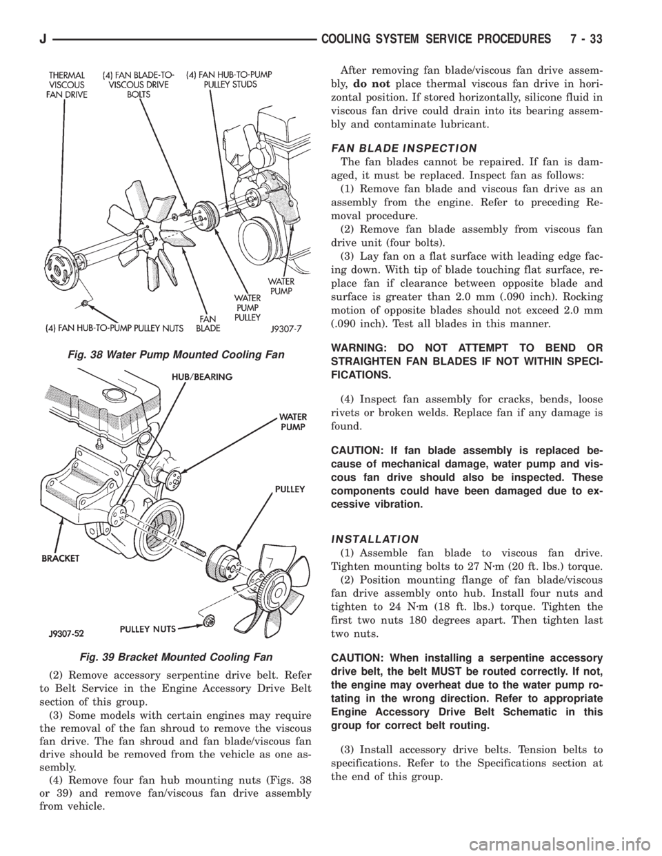
All models are equipped with a mechanical temper-
ature controlled fan. This thermal viscous fan drive
(Fig. 38) is a torque-and-temperature-sensitive clutch
unit. It automatically increases or decreases fan
speed to provide proper engine cooling. XJ models
equipped with a 4.0L 6-cylinder engine may also
have an auxiliary electrical cooling fan. This is with
models that have air conditioning and/or heavy duty
cooling.
REMOVAL
Some engines have the mechanical fan/viscous fan
drive assembly mounted directly to the water pump
hub (Fig. 38). It may also be mounted to a hub/bear-
ing attached to an aluminum bracket on the right
front side of engine (Fig. 39).
(1) Loosen but do not remove at this time, the four
fan hub mounting nuts (Figs. 38 or 39).
Fig. 36 Hose Clamp ToolÐTypical
Fig. 37 Clamp Number/Letter Location
7 - 32 COOLING SYSTEM SERVICE PROCEDURESJ
Page 258 of 2198
(2) Remove accessory serpentine drive belt. Refer
to Belt Service in the Engine Accessory Drive Belt
section of this group.
(3) Some models with certain engines may require
the removal of the fan shroud to remove the viscous
fan drive. The fan shroud and fan blade/viscous fan
drive should be removed from the vehicle as one as-
sembly.
(4) Remove four fan hub mounting nuts (Figs. 38
or 39) and remove fan/viscous fan drive assembly
from vehicle.After removing fan blade/viscous fan drive assem-
bly,do notplace thermal viscous fan drive in hori-
zontal position. If stored horizontally, silicone fluid in
viscous fan drive could drain into its bearing assem-
bly and contaminate lubricant.
FAN BLADE INSPECTION
The fan blades cannot be repaired. If fan is dam-
aged, it must be replaced. Inspect fan as follows:
(1) Remove fan blade and viscous fan drive as an
assembly from the engine. Refer to preceding Re-
moval procedure.
(2) Remove fan blade assembly from viscous fan
drive unit (four bolts).
(3) Lay fan on a flat surface with leading edge fac-
ing down. With tip of blade touching flat surface, re-
place fan if clearance between opposite blade and
surface is greater than 2.0 mm (.090 inch). Rocking
motion of opposite blades should not exceed 2.0 mm
(.090 inch). Test all blades in this manner.
WARNING: DO NOT ATTEMPT TO BEND OR
STRAIGHTEN FAN BLADES IF NOT WITHIN SPECI-
FICATIONS.
(4) Inspect fan assembly for cracks, bends, loose
rivets or broken welds. Replace fan if any damage is
found.
CAUTION: If fan blade assembly is replaced be-
cause of mechanical damage, water pump and vis-
cous fan drive should also be inspected. These
components could have been damaged due to ex-
cessive vibration.
INSTALLATION
(1) Assemble fan blade to viscous fan drive.
Tighten mounting bolts to 27 Nzm (20 ft. lbs.) torque.
(2) Position mounting flange of fan blade/viscous
fan drive assembly onto hub. Install four nuts and
tighten to 24 Nzm (18 ft. lbs.) torque. Tighten the
first two nuts 180 degrees apart. Then tighten last
two nuts.
CAUTION: When installing a serpentine accessory
drive belt, the belt MUST be routed correctly. If not,
the engine may overheat due to the water pump ro-
tating in the wrong direction. Refer to appropriate
Engine Accessory Drive Belt Schematic in this
group for correct belt routing.
(3) Install accessory drive belts. Tension belts to
specifications. Refer to the Specifications section at
the end of this group.
Fig. 38 Water Pump Mounted Cooling Fan
Fig. 39 Bracket Mounted Cooling Fan
JCOOLING SYSTEM SERVICE PROCEDURES 7 - 33
Page 259 of 2198
VISCOUS FAN DRIVE
DESCRIPTION AND OPERATION
Also refer to the previous section on Cooling Sys-
tem Fans.
The thermal viscous fan drive (Fig. 38 or 39) is a
silicone-fluid-filled coupling used to connect the fan
blades to either the engine or the water pump shaft.
The coupling allows the fan to be driven in a normal
manner. This is done at low engine speeds while lim-
iting the top speed of the fan to a predetermined
maximum level at higher engine speeds.
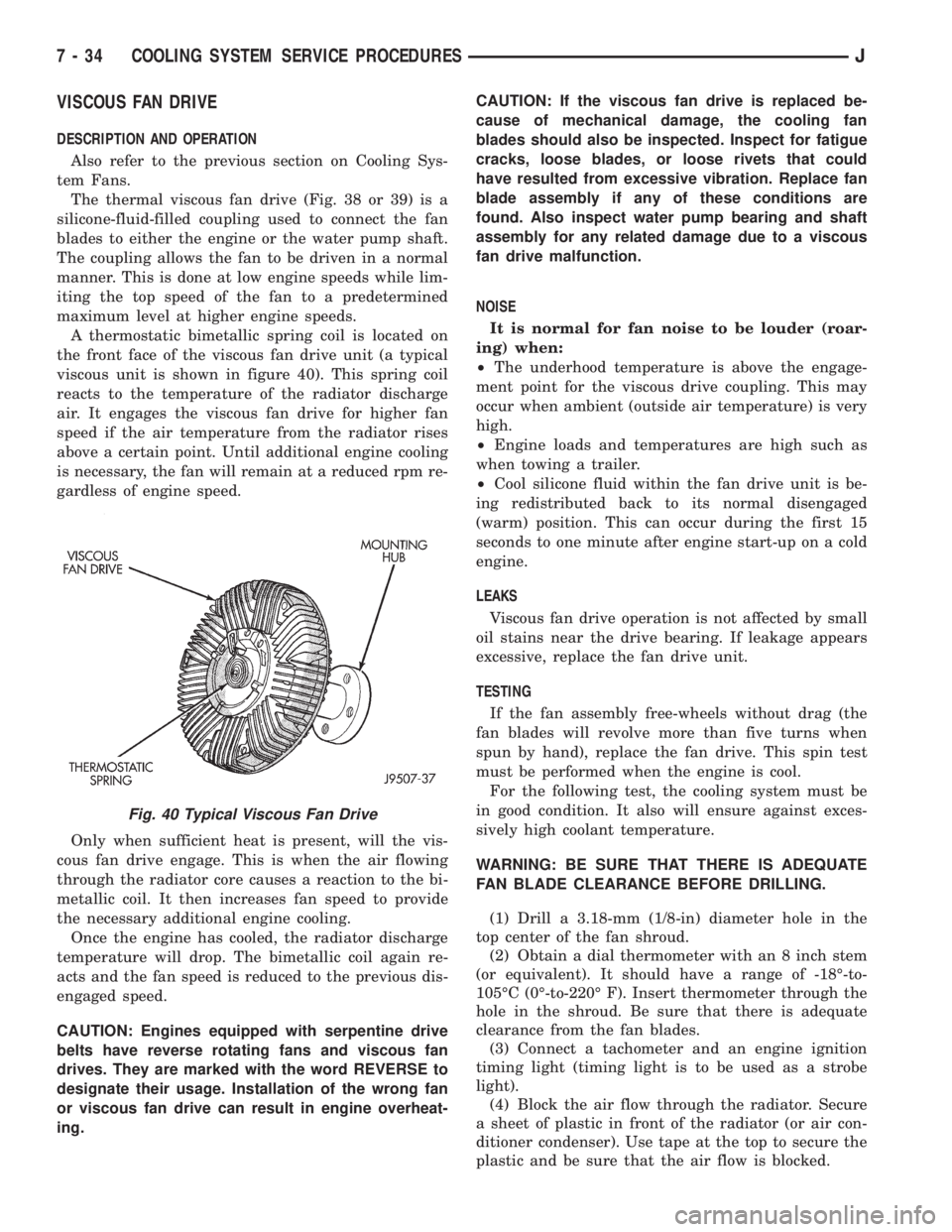
A thermostatic bimetallic spring coil is located on
the front face of the viscous fan drive unit (a typical
viscous unit is shown in figure 40). This spring coil
reacts to the temperature of the radiator discharge
air. It engages the viscous fan drive for higher fan
speed if the air temperature from the radiator rises
above a certain point. Until additional engine cooling
is necessary, the fan will remain at a reduced rpm re-
gardless of engine speed.
Only when sufficient heat is present, will the vis-
cous fan drive engage. This is when the air flowing
through the radiator core causes a reaction to the bi-
metallic coil. It then increases fan speed to provide
the necessary additional engine cooling.
Once the engine has cooled, the radiator discharge
temperature will drop. The bimetallic coil again re-
acts and the fan speed is reduced to the previous dis-
engaged speed.
CAUTION: Engines equipped with serpentine drive
belts have reverse rotating fans and viscous fan
drives. They are marked with the word REVERSE to
designate their usage. Installation of the wrong fan
or viscous fan drive can result in engine overheat-
ing.CAUTION: If the viscous fan drive is replaced be-
cause of mechanical damage, the cooling fan
blades should also be inspected. Inspect for fatigue
cracks, loose blades, or loose rivets that could
have resulted from excessive vibration. Replace fan
blade assembly if any of these conditions are
found. Also inspect water pump bearing and shaft
assembly for any related damage due to a viscous
fan drive malfunction.
NOISE
It is normal for fan noise to be louder (roar-
ing) when:
²The underhood temperature is above the engage-
ment point for the viscous drive coupling. This may
occur when ambient (outside air temperature) is very
high.
²Engine loads and temperatures are high such as
when towing a trailer.
²Cool silicone fluid within the fan drive unit is be-
ing redistributed back to its normal disengaged
(warm) position. This can occur during the first 15
seconds to one minute after engine start-up on a cold
engine.
LEAKS
Viscous fan drive operation is not affected by small
oil stains near the drive bearing. If leakage appears
excessive, replace the fan drive unit.
TESTING
If the fan assembly free-wheels without drag (the
fan blades will revolve more than five turns when
spun by hand), replace the fan drive. This spin test
must be performed when the engine is cool.
For the following test, the cooling system must be
in good condition. It also will ensure against exces-
sively high coolant temperature.
WARNING: BE SURE THAT THERE IS ADEQUATE
FAN BLADE CLEARANCE BEFORE DRILLING.
(1) Drill a 3.18-mm (1/8-in) diameter hole in the
top center of the fan shroud.
(2) Obtain a dial thermometer with an 8 inch stem
(or equivalent). It should have a range of -18É-to-
105ÉC (0É-to-220É F). Insert thermometer through the
hole in the shroud. Be sure that there is adequate
clearance from the fan blades.
(3) Connect a tachometer and an engine ignition
timing light (timing light is to be used as a strobe
light).
(4) Block the air flow through the radiator. Secure
a sheet of plastic in front of the radiator (or air con-
ditioner condenser). Use tape at the top to secure the
plastic and be sure that the air flow is blocked.
Fig. 40 Typical Viscous Fan Drive
7 - 34 COOLING SYSTEM SERVICE PROCEDURESJ