1995 JEEP CHEROKEE pcm wiring
[x] Cancel search: pcm wiringPage 243 of 2198
temperature, coolant is allowed to flow to the radia-
tor. This provides quick engine warmup and overall
temperature control.
An arrow plus the wordUPis stamped on the
front flange next to the air bleed. The wordsTO
RADare stamped on one arm of the thermostat.
They indicate the proper installed position.
The same thermostat is used for winter and sum-
mer seasons. An engine should not be operated with-
out a thermostat, except for servicing or testing.
Operating without a thermostat causes other prob-
lems. These are: longer engine warmup time, unreli-
able warmup performance, increased exhaust
emissions and crankcase condensation. This conden-
sation can result in sludge formation.
CAUTION: Do not operate an engine without a ther-
mostat, except for servicing or testing.
ON-BOARD DIAGNOSTICS
XJ and YJ models are equipped with On-Board Di-
agnostics for certain cooling system components. Re-
fer to On-Board Diagnostics (OBD) in the Diagnosis
section of this group for additional information. If the
powertrain control module (PCM) detects low engine
coolant temperature, it will record a Diagnostic Trou-
ble Code (DTC) in the PCM memory. The DTC num-
ber for low coolant temperature is 17. Do not change
a thermostat for lack of heat as indicated by the in-
strument panel gauge or heater performance unless a
DTC number 17 is present. Refer to the Diagnosis
section of this group for other probable causes. For
other DTC numbers, refer to On-Board Diagnostics
in the General Diagnosis section of Group 14, Fuel
Systems.
The DTC can also be accessed through the DRB
scan tool. Refer to the appropriate Powertrain Diag-
nostic Procedures manual for diagnostic information
and operation of the DRB scan tool.
REMOVAL
WARNING: DO NOT LOOSEN THE RADIATOR
DRAINCOCK WITH THE SYSTEM HOT AND PRES-
SURIZED. SERIOUS BURNS FROM THE COOLANT
CAN OCCUR.
DO NOT WASTE reusable coolant. If the solution
is clean, drain the coolant into a clean container for
reuse.
(1) Drain the coolant from the radiator until the
level is below the thermostat housing.
WARNING: CONSTANT TENSION HOSE CLAMPS
ARE USED ON MOST COOLING SYSTEM HOSES.
WHEN REMOVING OR INSTALLING, USE ONLY
TOOLS DESIGNED FOR SERVICING THIS TYPE OF
CLAMP, SUCH AS SPECIAL CLAMP TOOL (NUMBER
6094) (FIG. 15). SNAP-ON CLAMP TOOL (NUMBER
HPC-20) MAY BE USED FOR LARGER CLAMPS. AL-
WAYS WEAR SAFETY GLASSES WHEN SERVICING
CONSTANT TENSION CLAMPS.
CAUTION: A number or letter is stamped into the
tongue of constant tension clamps (Fig. 16). If re-
placement is necessary, use only an original equip-
ment clamp with matching number or letter.
(2) Remove radiator upper hose and heater hose at
thermostat housing.
(3) Disconnect wiring connector at engine coolant
temperature sensor.
(4) Remove thermostat housing mounting bolts,
thermostat housing, gasket and thermostat (Fig. 17).
Discard old gasket.
(5) Clean the gasket mating surfaces.
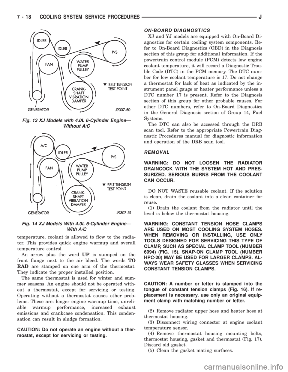
Fig. 13 XJ Models with 4.0L 6-Cylinder EngineÐ
Without A/C
Fig. 14 XJ Models With 4.0L 6-Cylinder EngineÐ
With A/C
7 - 18 COOLING SYSTEM SERVICE PROCEDURESJ
Page 272 of 2198
ELECTRICAL
GROUP INDEX
Group Group
AUDIO SYSTEMS........................ 8F
BATTERY/STARTER/GENERATOR SERVICE.... 8B
BATTERY/STARTING/CHARGING SYSTEMS
DIAGNOSTICS......................... 8A
CHIME/BUZZER WARNING SYSTEMS........ 8U
HORNS................................ 8G
IGNITION SYSTEMS...................... 8D
INSTRUMENT PANEL AND GAUGES......... 8E
LAMPS................................ 8L
OVERHEAD CONSOLE.................... 8C
POWER LOCKS.......................... 8P
POWER MIRRORS....................... 8TPOWER SEATS.......................... 8R
POWER WINDOWS....................... 8S
REAR WINDOW DEFOGGER............... 8N
RESTRAINT SYSTEMS................... 8M
TURN SIGNAL AND HAZARD WARNING
SYSTEMS............................. 8J
VEHICLE SPEED CONTROL SYSTEM......... 8H
WIPER AND WASHER SYSTEMS............ 8K
XJ WIRING DIAGRAMS-LEFT HAND DRIVE . . . 8W
XJ WIRING DIAGRAMS-RIGHT HAND DRIVE . 8W
YJ WIRING DIAGRAMS.................. 8W
BATTERY/STARTING/CHARGING SYSTEMS DIAGNOSTICS
CONTENTS
page page
BATTERY............................... 2
CHARGING SYSTEM..................... 17
IGNITION-OFF DRAW.................... 10SPECIFICATIONS........................ 23
STARTING SYSTEM...................... 11
USING ON-BOARD DIAGNOSTIC SYSTEM.... 22
GENERAL INFORMATION
The battery, starting, and charging systems operate
with one another; therefore, they must be tested as a
complete system. In order for the vehicle to start and
charge properly, all of the components involved in
these systems must perform within specifications.
Group 8A covers battery, starting (Fig. 1) and
charging (Fig. 2) system diagnostic procedures. These
procedures include the most basic conventional diag-
nostic methods, to On-Board Diagnostics (OBD) builtinto the Powertrain Control Module (PCM). Use of an
induction milliamp ammeter, volt/ohmmeter, battery
charger, carbon pile rheostat (load tester), and 12-
volt test lamp will be required.
All OBD-sensed systems are monitored by the
PCM. Each monitored circuit is assigned a Diagnos-
tic Trouble Code (DTC). The PCM will store a DTC in
electronic memory for any failure it detects. See Us-
ing On-Board Diagnostic System in this group for
more information.
JELECTRICAL 8A - 1
Page 281 of 2198
IGNITION-OFF DRAW
GENERAL INFORMATION
Ignition-Off Draw (IOD) refers to power being
drained from the battery with the ignition switch
turned OFF. A normal vehicle electrical system will
draw from 5 to 20 milliamps (0.005 - 0.020 amps).
This is with the ignition switch in the OFF position,
and all non-ignition controlled circuits in proper
working order. The 20 milliamps are needed to sup-
ply PCM memory, digital clock memory, and electron-
ically-tuned radio memory.
A vehicle that has not been operated for approxi-
mately 20 days, may discharge the battery to an in-
adequate level. When a vehicle will not be used for
20 days or more (stored), remove the IOD fuse in the
Power Distribution Center (PDC). This will reduce
battery discharging.
Excessive battery drain can be caused by:
²electrical items left on
²faulty or improperly adjusted switches
²internally shorted generator
²intermittent shorts in the wiring.
If the IOD is over 20 milliamps, the problem must
be found and corrected before replacing a battery. In
most cases, the battery can be charged and returned
to service.
DIAGNOSIS
Testing for high-amperage IOD must be per-
formed first to prevent damage to most milli-
amp meters.
(1) Verify that all electrical accessories are off.
Turn off all lamps, remove ignition key, and close all
doors. If the vehicle is equipped with illuminated en-
try or electronically-tuned radio, allow the systems to
automatically shut off (time out). This may take up
to 3 minutes.
(2) Determine that the underhood lamp is operat-
ing properly, then disconnect or remove bulb.
(3) Disconnect negative cable from battery.
(4) Connect a typical 12-volt test lamp (low-watt-
age bulb) between the negative cable clamp and the
battery negative terminal. Make sure that the doors
remain closed so that illuminated entry is not acti-
vated.The test lamp may light brightly for up to 3 min-
utes, or may not light at all, depending upon the ve-
hicle's electrical equipment. The term brightly, as
used throughout the following tests, implies the
brightness of the test lamp will be the same as if it
were connected across the battery.
The test lamp must be securely clamped to the neg-
ative cable clamp and battery negative terminal. If
the test lamp becomes disconnected during any part
of the IOD test, the electronic timer function will be
activated and all tests must be repeated.
(5) After 3 minutes the test lamp should turn off
or be dimly lit, depending upon the vehicle's electri-
cal equipment. If the test lamp remains brightly lit,
do not disconnect it. Remove each fuse or circuit
breaker (refer to Group 8W - Wiring Diagrams) until
test lamp is either off or dimly lit. This will isolate
each circuit and identify the source of the high-am-
perage draw.
If the test lamp is still brightly lit after disconnect-
ing each fuse and circuit breaker, disconnect the wir-
ing harness from the generator. If test lamp now
turns off or is dimly lit, see Charging System in this
group to diagnose faulty generator. Do not disconnect
the test lamp.
After high-amperage IOD has been corrected, low-
amperage IOD may be checked. It is now safe to in-
stall a milliamp meter to check for low- amperage
IOD.
(6) With test lamp still connected securely, clamp a
milliamp meter between battery negative terminal
and negative cable clamp.
Do not open any doors or turn on any electri-
cal accessories with the test lamp disconnected
or the milliamp meter may be damaged.
(7) Disconnect test lamp. Observe milliamp meter.
The current draw should not exceed 0.020 amp. If
draw exceeds 20 milliamps, isolate each circuit by re-
moving circuit breakers and fuses. The milliamp
meter reading will drop when the source of the draw
is disconnected. Repair this circuit as necessary,
whether a wiring short, incorrect switch adjustment
or a component failure is found.
8A - 10 BATTERY/STARTING/CHARGING SYSTEMS DIAGNOSTICSJ
Page 288 of 2198
CHARGING SYSTEM
GENERAL INFORMATION
The charging system consists of:
²generator
²voltage regulator circuitry (within PCM)
²ignition switch
²battery
²generator warning lamp or voltmeter (depending
on vehicle equipment)
²wiring harness and connections.
Following is a general description of the major
charging system components. Refer to Group 8W -
Wiring Diagrams for complete circuit descriptions
and diagrams.
The charging system is turned on and off with the
ignition switch. When the ignition switch is turned to
the ON position, battery voltage is applied to the
generator rotor through one of the two field termi-
nals to produce a magnetic field. The generator is
driven by the engine through a serpentine belt and
pulley arrangement.
As the energized rotor begins to rotate within the
generator, the spinning magnetic field induces a cur-
rent into the windings of the stator coil. Once the
generator begins producing sufficient current, it also
provides the current needed to energize the rotor.
The wye (Y) type stator winding connections de-
liver the induced AC current to 3 positive and 3 neg-
ative diodes for rectification. From the diodes,
rectified DC current is delivered to the vehicle elec-
trical system through the generator battery and
ground terminals.
The amount of DC current produced by the gener-
ator is controlled by the generator voltage regulator
(field control) circuitry, contained within the Power-
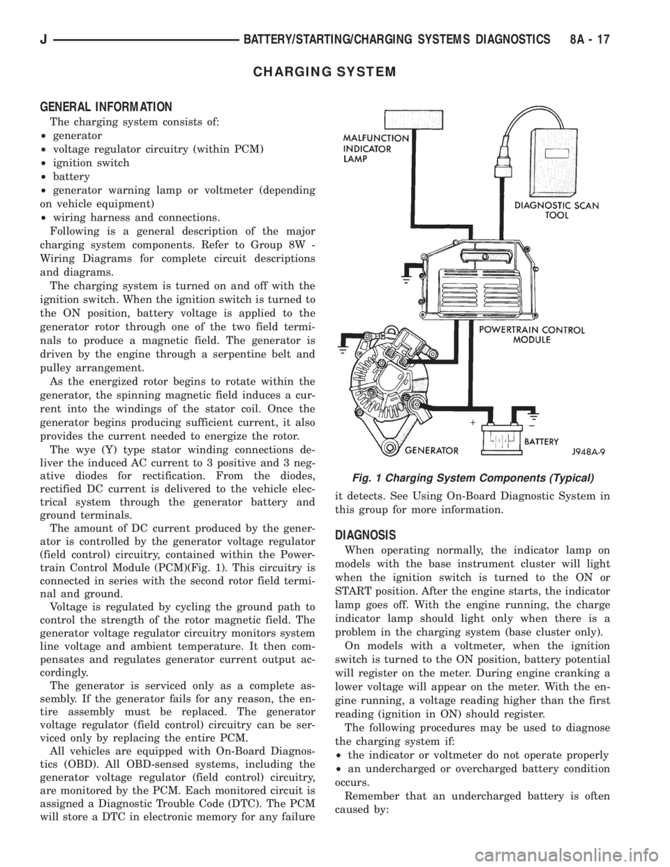
train Control Module (PCM)(Fig. 1). This circuitry is
connected in series with the second rotor field termi-
nal and ground.
Voltage is regulated by cycling the ground path to
control the strength of the rotor magnetic field. The
generator voltage regulator circuitry monitors system
line voltage and ambient temperature. It then com-
pensates and regulates generator current output ac-
cordingly.
The generator is serviced only as a complete as-
sembly. If the generator fails for any reason, the en-
tire assembly must be replaced. The generator
voltage regulator (field control) circuitry can be ser-
viced only by replacing the entire PCM.
All vehicles are equipped with On-Board Diagnos-
tics (OBD). All OBD-sensed systems, including the
generator voltage regulator (field control) circuitry,
are monitored by the PCM. Each monitored circuit is
assigned a Diagnostic Trouble Code (DTC). The PCM
will store a DTC in electronic memory for any failureit detects. See Using On-Board Diagnostic System in
this group for more information.
DIAGNOSIS
When operating normally, the indicator lamp on
models with the base instrument cluster will light
when the ignition switch is turned to the ON or
START position. After the engine starts, the indicator
lamp goes off. With the engine running, the charge
indicator lamp should light only when there is a
problem in the charging system (base cluster only).
On models with a voltmeter, when the ignition
switch is turned to the ON position, battery potential
will register on the meter. During engine cranking a
lower voltage will appear on the meter. With the en-
gine running, a voltage reading higher than the first
reading (ignition in ON) should register.
The following procedures may be used to diagnose
the charging system if:
²the indicator or voltmeter do not operate properly
²an undercharged or overcharged battery condition
occurs.
Remember that an undercharged battery is often
caused by:
Fig. 1 Charging System Components (Typical)
JBATTERY/STARTING/CHARGING SYSTEMS DIAGNOSTICS 8A - 17
Page 317 of 2198

DIAGNOSTICS/SERVICE PROCEDURES
INDEX
page page
Automatic Shutdown (ASD) Relay Test.......... 6
Camshaft Position Sensor Test................ 6
Crankshaft Position Sensor Test............... 7
Distributor Cap............................ 7
Distributor Rotor........................... 8
DRB Scan Tool............................ 8
Engine Coolant Temperature Sensor Test........ 9
General Information........................ 6
Ignition Coil.............................. 9
Ignition Secondary Circuit Diagnosis........... 10Ignition Timing............................ 11
Intake Manifold Air Temperature Sensor Test..... 11
Manifold Absolute Pressure (MAP) Sensor Test . . . 11
On-Board Diagnostics...................... 15
Oxygen (O2S) Sensor Tests................. 15
Powertrain Control Module (PCM)............. 11
Spark Plug Secondary Cables................ 14
Spark Plugs............................. 12
Throttle Position Sensor Test................. 15
GENERAL INFORMATION
This section of the group, Diagnostics/Service Pro-
cedures, will discuss basic ignition system diagnostics
and service adjustments.
For system operation and component identification,
refer to the Component Identification/System Opera-
tion section of this group.
For removal or installation of ignition system com-
ponents, refer to the Component Removal/Installa-
tion section of this group.
For other useful information, refer to the On-Board
Diagnostics section.
For operation of the DRB Scan Tool, refer to the
appropriate Powertrain Diagnostic Procedures ser-
vice manual.
AUTOMATIC SHUTDOWN (ASD) RELAY TEST
To perform a complete test of this relay and its cir-
cuitry, refer to the DRB scan tool. Also refer to the
appropriate Powertrain Diagnostics Procedures man-
ual. To test the relay only, refer to RelaysÐOpera-
tion/Testing in the Group 14, Fuel Systems section.
CAMSHAFT POSITION SENSOR TEST
To perform a complete test of this sensor and its
circuitry, refer to the DRB scan tool. Also refer to the
appropriate Powertrain Diagnostics Procedures man-
ual. To test the sensor only, refer to the following:
The camshaft position sensor is located in the dis-
tributor (Fig. 1).
To perform a complete test of this sensor and its
circuitry, refer to the DRB scan tool. Also refer to the
appropriate Powertrain Diagnostics Procedures man-
ual. To test the sensor only, refer to the following:
For this test, an analog (non-digital) voltme-
ter is needed.Do not remove the distributor connec-
tor from the distributor. Using small paper clips,
insert them into the backside of the distributor wire
harness connector to make contact with the termi-nals. Be sure that the connector is not damaged
when inserting the paper clips. Attach voltmeter
leads to these paper clips.
(1) Connect the positive (+) voltmeter lead into the
sensor output wire. This is at done the distributor
wire harness connector. For wire identification, refer
to Group 8W, Wiring Diagrams.
(2) Connect the negative (-) voltmeter lead into the
ground wire. For wire identification, refer to Group
8W, Wiring Diagrams.
(3) Set the voltmeter to the 15 Volt DC scale.
(4) Remove distributor cap from distributor (two
screws). Rotate (crank) the engine until the distribu-
tor rotor is pointed to approximately the 11 o'clock
position. The movable pulse ring should now be
within the sensor pickup.
(5) Turn ignition key to ON position. The voltmeter
should read approximately 5.0 volts.
(6) If voltage is not present, check the voltmeter
leads for a good connection.
(7) If voltage is still not present, check for voltage
at the supply wire. For wire identification, refer to
Group 8W, Wiring Diagrams.
Fig. 1 Camshaft Position SensorÐTypical
8D - 6 IGNITION SYSTEMSJ
Page 322 of 2198
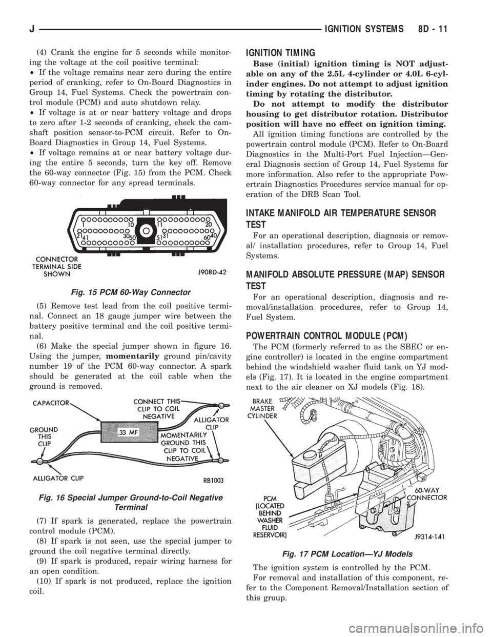
(4) Crank the engine for 5 seconds while monitor-
ing the voltage at the coil positive terminal:
²If the voltage remains near zero during the entire
period of cranking, refer to On-Board Diagnostics in
Group 14, Fuel Systems. Check the powertrain con-
trol module (PCM) and auto shutdown relay.
²If voltage is at or near battery voltage and drops
to zero after 1-2 seconds of cranking, check the cam-
shaft position sensor-to-PCM circuit. Refer to On-
Board Diagnostics in Group 14, Fuel Systems.
²If voltage remains at or near battery voltage dur-
ing the entire 5 seconds, turn the key off. Remove
the 60-way connector (Fig. 15) from the PCM. Check
60-way connector for any spread terminals.
(5) Remove test lead from the coil positive termi-
nal. Connect an 18 gauge jumper wire between the
battery positive terminal and the coil positive termi-
nal.
(6) Make the special jumper shown in figure 16.
Using the jumper,momentarilyground pin/cavity
number 19 of the PCM 60-way connector. A spark
should be generated at the coil cable when the
ground is removed.
(7) If spark is generated, replace the powertrain
control module (PCM).
(8) If spark is not seen, use the special jumper to
ground the coil negative terminal directly.
(9) If spark is produced, repair wiring harness for
an open condition.
(10) If spark is not produced, replace the ignition
coil.IGNITION TIMING
Base (initial) ignition timing is NOT adjust-
able on any of the 2.5L 4-cylinder or 4.0L 6-cyl-
inder engines. Do not attempt to adjust ignition
timing by rotating the distributor.
Do not attempt to modify the distributor
housing to get distributor rotation. Distributor
position will have no effect on ignition timing.
All ignition timing functions are controlled by the
powertrain control module (PCM). Refer to On-Board
Diagnostics in the Multi-Port Fuel InjectionÐGen-
eral Diagnosis section of Group 14, Fuel Systems for
more information. Also refer to the appropriate Pow-
ertrain Diagnostics Procedures service manual for op-
eration of the DRB Scan Tool.
INTAKE MANIFOLD AIR TEMPERATURE SENSOR
TEST
For an operational description, diagnosis or remov-
al/ installation procedures, refer to Group 14, Fuel
Systems.
MANIFOLD ABSOLUTE PRESSURE (MAP) SENSOR
TEST
For an operational description, diagnosis and re-
moval/installation procedures, refer to Group 14,
Fuel System.
POWERTRAIN CONTROL MODULE (PCM)
The PCM (formerly referred to as the SBEC or en-
gine controller) is located in the engine compartment
behind the windshield washer fluid tank on YJ mod-
els (Fig. 17). It is located in the engine compartment
next to the air cleaner on XJ models (Fig. 18).
The ignition system is controlled by the PCM.
For removal and installation of this component, re-
fer to the Component Removal/Installation section of
this group.
Fig. 15 PCM 60-Way Connector
Fig. 16 Special Jumper Ground-to-Coil Negative
Terminal
Fig. 17 PCM LocationÐYJ Models
JIGNITION SYSTEMS 8D - 11
Page 328 of 2198
COMPONENT REMOVAL/INSTALLATION
INDEX
page page
Automatic Shutdown (ASD) Relay............. 17
Camshaft Position Sensor................... 17
Crankshaft Position Sensor.................. 17
Distributor............................... 19
Engine Coolant Temperature Sensor........... 19
General Information....................... 17
Ignition Coil............................. 22Intake Manifold Air Temperature Sensor......... 23
Manifold Absolute Pressure (MAP) Sensor....... 23
Oxygen (O2S) Sensor...................... 23
Powertrain Control Module (PCM)............. 23
Spark Plug Secondary Cables................ 24
Spark Plugs............................. 23
Throttle Position Sensor (TPS)............... 25
GENERAL INFORMATION
This section of the group, Component Removal/In-
stallation, will discuss the removal and installation
of ignition system components.
For basic ignition system diagnostics and service
adjustments, refer to the Diagnostics/Service Proce-
dures section of this group.
For system operation and component identification,
refer to the Component Identification/System Opera-
tion section of this group.
AUTOMATIC SHUTDOWN (ASD) RELAY
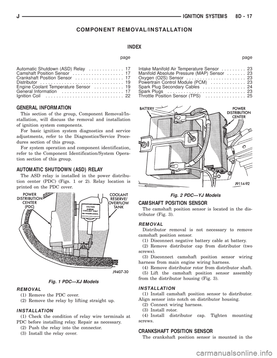
The ASD relay is installed in the power distribu-
tion center (PDC) (Figs. 1 or 2). Relay location is
printed on the PDC cover.
REMOVAL
(1) Remove the PDC cover.
(2) Remove the relay by lifting straight up.
INSTALLATION
(1) Check the condition of relay wire terminals at
PDC before installing relay. Repair as necessary.
(2) Push the relay into the connector.
(3) Install the relay cover.
CAMSHAFT POSITION SENSOR
The camshaft position sensor is located in the dis-
tributor (Fig. 3).
REMOVAL
Distributor removal is not necessary to remove
camshaft position sensor.
(1) Disconnect negative battery cable at battery.
(2) Remove distributor cap from distributor (two
screws).
(3) Disconnect camshaft position sensor wiring
harness from main engine wiring harness.
(4) Remove distributor rotor from distributor shaft.
(5) Lift the camshaft position sensor assembly
from the distributor housing (Fig. 3).
INSTALLATION
(1) Install camshaft position sensor to distributor.
Align sensor into notch on distributor housing.
(2) Connect wiring harness.
(3) Install rotor.
(4) Install distributor cap. Tighten mounting
screws.
CRANKSHAFT POSITION SENSOR
The crankshaft position sensor is mounted in the
Fig. 1 PDCÐXJ Models
Fig. 2 PDCÐYJ Models
JIGNITION SYSTEMS 8D - 17
Page 349 of 2198
(5) Probe cavity B1 of cluster connector A. Check
for continuity to a good ground. There should be no
continuity. If OK, go to next step. If not OK, repair
short circuit as required.
(6) Still probing cavity B1 of cluster connector A,
check for continuity to cavity B of sending unit body
half connector. There should be continuity. If OK, re-
place gauge. If not OK, repair open circuit as re-
quired.
OIL PRESSURE GAUGE
The diagnosis found here addresses an inoperative
gauge condition. If the problem being diagnosed is re-
lated to gauge accuracy, be certain to confirm that
problem is with gauge and not with engine oiling sys-
tem performance. Actual engine oil pressure should
be checked with a test gauge and compared to gauge
readings before you proceed with gauge diagnosis.
Refer to Group 9 - Engines for more information.
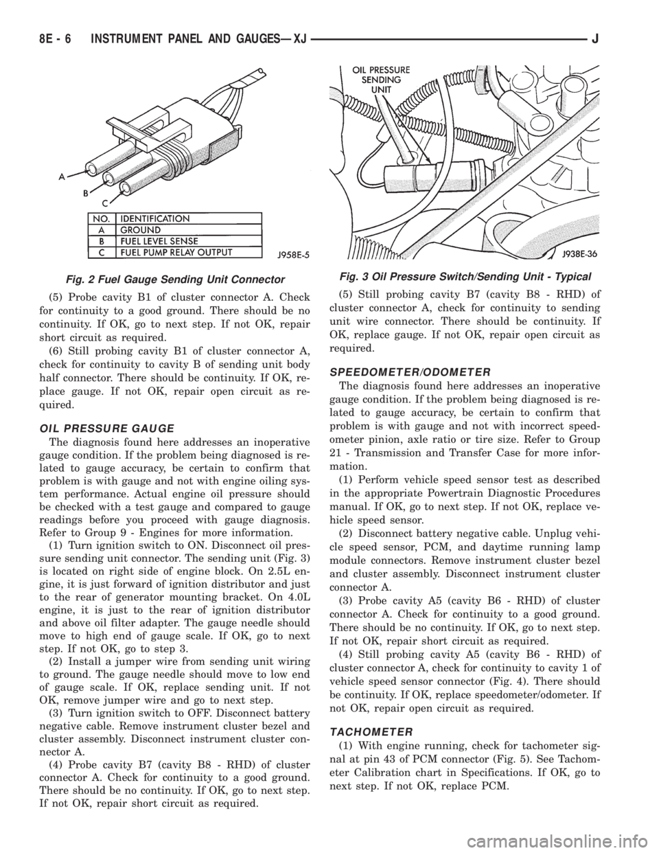
(1) Turn ignition switch to ON. Disconnect oil pres-
sure sending unit connector. The sending unit (Fig. 3)
is located on right side of engine block. On 2.5L en-
gine, it is just forward of ignition distributor and just
to the rear of generator mounting bracket. On 4.0L
engine, it is just to the rear of ignition distributor
and above oil filter adapter. The gauge needle should
move to high end of gauge scale. If OK, go to next
step. If not OK, go to step 3.
(2) Install a jumper wire from sending unit wiring
to ground. The gauge needle should move to low end
of gauge scale. If OK, replace sending unit. If not
OK, remove jumper wire and go to next step.
(3) Turn ignition switch to OFF. Disconnect battery
negative cable. Remove instrument cluster bezel and
cluster assembly. Disconnect instrument cluster con-
nector A.
(4) Probe cavity B7 (cavity B8 - RHD) of cluster
connector A. Check for continuity to a good ground.
There should be no continuity. If OK, go to next step.
If not OK, repair short circuit as required.(5) Still probing cavity B7 (cavity B8 - RHD) of
cluster connector A, check for continuity to sending
unit wire connector. There should be continuity. If
OK, replace gauge. If not OK, repair open circuit as
required.
SPEEDOMETER/ODOMETER
The diagnosis found here addresses an inoperative
gauge condition. If the problem being diagnosed is re-
lated to gauge accuracy, be certain to confirm that
problem is with gauge and not with incorrect speed-
ometer pinion, axle ratio or tire size. Refer to Group
21 - Transmission and Transfer Case for more infor-
mation.
(1) Perform vehicle speed sensor test as described
in the appropriate Powertrain Diagnostic Procedures
manual. If OK, go to next step. If not OK, replace ve-
hicle speed sensor.
(2) Disconnect battery negative cable. Unplug vehi-
cle speed sensor, PCM, and daytime running lamp
module connectors. Remove instrument cluster bezel
and cluster assembly. Disconnect instrument cluster
connector A.
(3) Probe cavity A5 (cavity B6 - RHD) of cluster
connector A. Check for continuity to a good ground.
There should be no continuity. If OK, go to next step.
If not OK, repair short circuit as required.
(4) Still probing cavity A5 (cavity B6 - RHD) of
cluster connector A, check for continuity to cavity 1 of
vehicle speed sensor connector (Fig. 4). There should
be continuity. If OK, replace speedometer/odometer. If
not OK, repair open circuit as required.
TACHOMETER
(1) With engine running, check for tachometer sig-
nal at pin 43 of PCM connector (Fig. 5). See Tachom-
eter Calibration chart in Specifications. If OK, go to
next step. If not OK, replace PCM.
Fig. 2 Fuel Gauge Sending Unit ConnectorFig. 3 Oil Pressure Switch/Sending Unit - Typical
8E - 6 INSTRUMENT PANEL AND GAUGESÐXJJ