1995 JEEP CHEROKEE pcm wiring
[x] Cancel search: pcm wiringPage 1256 of 2198
PCM SYSTEM SCHEMATICS
Powertrain control system schematics for the 2.5L
4-cylinder and 4.0L 6-cylinder engines are shown in
figures 29, 30, 31 and 32.
These schematics are displayed as a quick refer-
ence only. They are not intended to be all-inclusive.
Refer to the Wiring Diagrams section for detailed in-
formation.
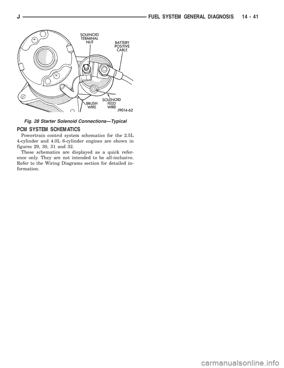
Fig. 28 Starter Solenoid ConnectionsÐTypical
JFUEL SYSTEM GENERAL DIAGNOSIS 14 - 41
Page 1262 of 2198
Test the resistance of the wire harness. Do this be-
tween the powertrain control module (PCM) wire
harness connector terminal-2 and the sensor connec-
tor terminal. Also test terminal-4 to the sensor con-
nector terminal. Repair the wire harness as
necessary if the resistance is greater than 1 ohm.
FUEL PUMP RELAY TESTING
For testing this relay, refer to RelaysÐOperation/
Testing in this section of the group.
MANIFOLD ABSOLUTE PRESSURE (MAP) SENSOR
TEST
To perform a complete test of the MAP sensor and
its circuitry, refer to DRB scan tool and appropriate
Powertrain Diagnostics Procedures manual. To test
the sensor only, refer to the following:
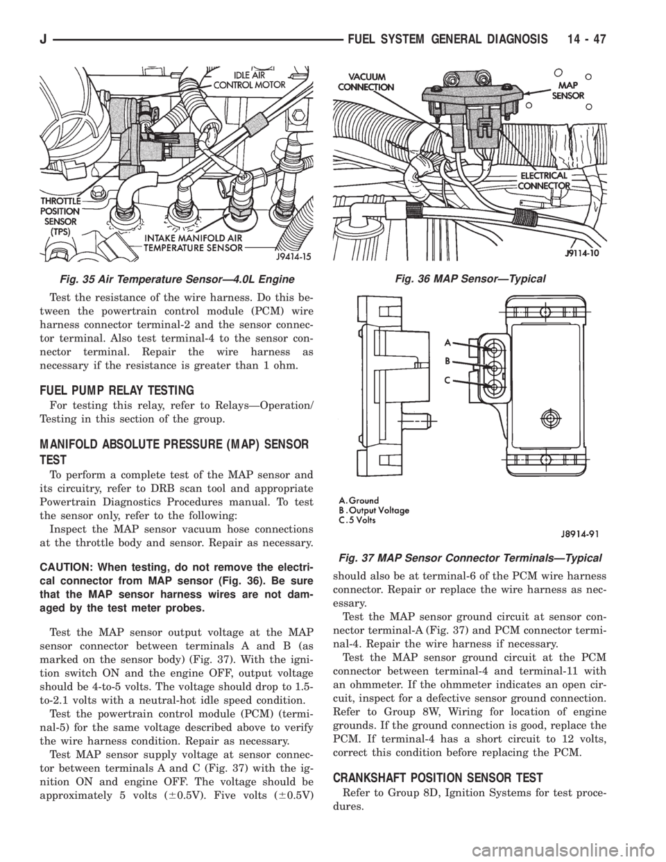
Inspect the MAP sensor vacuum hose connections
at the throttle body and sensor. Repair as necessary.
CAUTION: When testing, do not remove the electri-
cal connector from MAP sensor (Fig. 36). Be sure
that the MAP sensor harness wires are not dam-
aged by the test meter probes.
Test the MAP sensor output voltage at the MAP
sensor connector between terminals A and B (as
marked on the sensor body) (Fig. 37). With the igni-
tion switch ON and the engine OFF, output voltage
should be 4-to-5 volts. The voltage should drop to 1.5-
to-2.1 volts with a neutral-hot idle speed condition.
Test the powertrain control module (PCM) (termi-
nal-5) for the same voltage described above to verify
the wire harness condition. Repair as necessary.
Test MAP sensor supply voltage at sensor connec-
tor between terminals A and C (Fig. 37) with the ig-
nition ON and engine OFF. The voltage should be
approximately 5 volts (60.5V). Five volts (60.5V)should also be at terminal-6 of the PCM wire harness
connector. Repair or replace the wire harness as nec-
essary.
Test the MAP sensor ground circuit at sensor con-
nector terminal-A (Fig. 37) and PCM connector termi-
nal-4. Repair the wire harness if necessary.
Test the MAP sensor ground circuit at the PCM
connector between terminal-4 and terminal-11 with
an ohmmeter. If the ohmmeter indicates an open cir-
cuit, inspect for a defective sensor ground connection.
Refer to Group 8W, Wiring for location of engine
grounds. If the ground connection is good, replace the
PCM. If terminal-4 has a short circuit to 12 volts,
correct this condition before replacing the PCM.
CRANKSHAFT POSITION SENSOR TEST
Refer to Group 8D, Ignition Systems for test proce-
dures.
Fig. 35 Air Temperature SensorÐ4.0L EngineFig. 36 MAP SensorÐTypical
Fig. 37 MAP Sensor Connector TerminalsÐTypical
JFUEL SYSTEM GENERAL DIAGNOSIS 14 - 47
Page 1263 of 2198
EXTENDED IDLE SWITCH TEST
OPTIONAL POLICE PACKAGE ONLY
OPERATION
The extended idle switch is used to raise the en-
gine idle speed to approximately 1000 rpm when the
shifter is in either the Park or Neutral position. A
rocker-type 2-wire switch (extended idle switch) is
mounted to the instrument panel.This switch is
available only with 4.0L engine when supplied
with the optional police package.
TESTING
The extended idle switch will control a ground cir-
cuit going to the powertrain control module (PCM).
When a ground signal (through this switch) has been
received at pin number 10 in the PCM, engine idle
speed will increase.
Bring the engine to normal operating temperature
and turn the extended idle switch to the ON position.
Engine speed should now increase to approximately
1000 rpm when the shifter is in either the Park or
Neutral position. If engine speed does not increase,
apply a good ground to pin number 10 at the PCM
using a small paper clip. Be careful not to damage
the wiring with the paper clip. If the engine speed
now increases, it can be assumed that the PCM is
functioning correctly. Check the instrument panel
mounted switch for a closed ground circuit when in
the ON position. If the engine speed will not increase
after applying a ground to pin number 10, replace
the PCM. Refer to Group 8W, Wiring Diagrams for
circuit and wiring information.
THROTTLE POSITION SENSOR (TPS) TEST
To perform a complete test of the sensor and its cir-
cuitry, refer to DRB scan tool and appropriate Pow-
ertrain Diagnostics Procedures manual. To test the
sensor only, refer to the following:
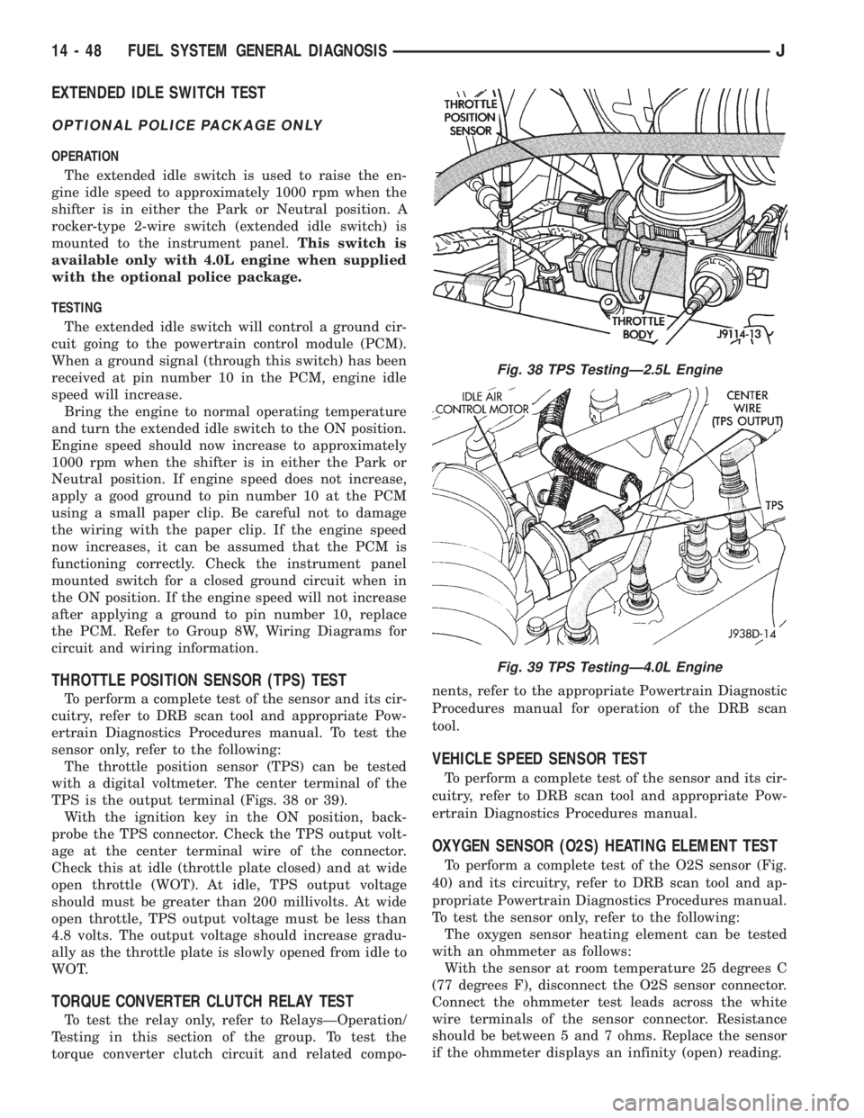
The throttle position sensor (TPS) can be tested
with a digital voltmeter. The center terminal of the
TPS is the output terminal (Figs. 38 or 39).
With the ignition key in the ON position, back-
probe the TPS connector. Check the TPS output volt-
age at the center terminal wire of the connector.
Check this at idle (throttle plate closed) and at wide
open throttle (WOT). At idle, TPS output voltage
should must be greater than 200 millivolts. At wide
open throttle, TPS output voltage must be less than
4.8 volts. The output voltage should increase gradu-
ally as the throttle plate is slowly opened from idle to
WOT.
TORQUE CONVERTER CLUTCH RELAY TEST
To test the relay only, refer to RelaysÐOperation/
Testing in this section of the group. To test the
torque converter clutch circuit and related compo-nents, refer to the appropriate Powertrain Diagnostic
Procedures manual for operation of the DRB scan
tool.
VEHICLE SPEED SENSOR TEST
To perform a complete test of the sensor and its cir-
cuitry, refer to DRB scan tool and appropriate Pow-
ertrain Diagnostics Procedures manual.
OXYGEN SENSOR (O2S) HEATING ELEMENT TEST
To perform a complete test of the O2S sensor (Fig.
40) and its circuitry, refer to DRB scan tool and ap-
propriate Powertrain Diagnostics Procedures manual.
To test the sensor only, refer to the following:
The oxygen sensor heating element can be tested
with an ohmmeter as follows:
With the sensor at room temperature 25 degrees C
(77 degrees F), disconnect the O2S sensor connector.
Connect the ohmmeter test leads across the white
wire terminals of the sensor connector. Resistance
should be between 5 and 7 ohms. Replace the sensor
if the ohmmeter displays an infinity (open) reading.
Fig. 38 TPS TestingÐ2.5L Engine
Fig. 39 TPS TestingÐ4.0L Engine
14 - 48 FUEL SYSTEM GENERAL DIAGNOSISJ
Page 1266 of 2198
(8) Disconnect jumper wires from relay and 12 Volt
power source.
If continuity or resistance tests did not pass, re-
place relay. If tests passed, refer to Group 8W, Wiring
Diagrams for additional circuit information. Also re-
fer to the appropriate Powertrain Diagnostic Proce-
dures manual for operation of the DRB scan tool.
STARTER MOTOR RELAY TEST
Refer to Group 8A, Battery/Starting/Charging/Sys-
tem Diagnostics, for starter motor relay testing.
FUEL INJECTOR TEST
To perform a complete test of the fuel injectors and
their circuitry, refer to DRB scan tool and appropri-
ate Powertrain Diagnostics Procedures manual. To
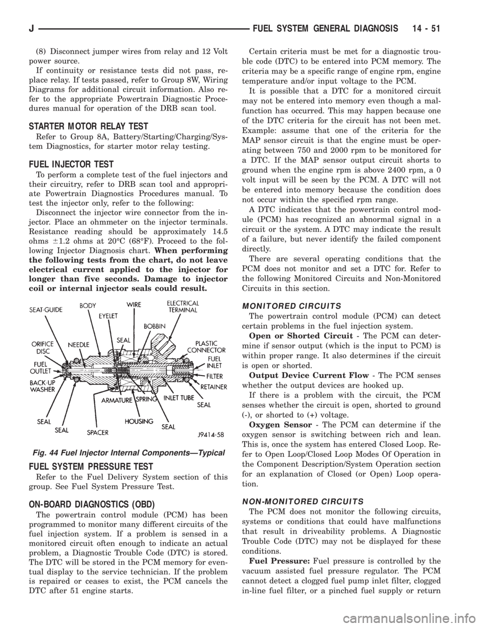
test the injector only, refer to the following:
Disconnect the injector wire connector from the in-
jector. Place an ohmmeter on the injector terminals.
Resistance reading should be approximately 14.5
ohms61.2 ohms at 20ÉC (68ÉF). Proceed to the fol-
lowing Injector Diagnosis chart.When performing
the following tests from the chart, do not leave
electrical current applied to the injector for
longer than five seconds. Damage to injector
coil or internal injector seals could result.
FUEL SYSTEM PRESSURE TEST
Refer to the Fuel Delivery System section of this
group. See Fuel System Pressure Test.
ON-BOARD DIAGNOSTICS (OBD)
The powertrain control module (PCM) has been
programmed to monitor many different circuits of the
fuel injection system. If a problem is sensed in a
monitored circuit often enough to indicate an actual
problem, a Diagnostic Trouble Code (DTC) is stored.
The DTC will be stored in the PCM memory for even-
tual display to the service technician. If the problem
is repaired or ceases to exist, the PCM cancels the
DTC after 51 engine starts.Certain criteria must be met for a diagnostic trou-
ble code (DTC) to be entered into PCM memory. The
criteria may be a specific range of engine rpm, engine
temperature and/or input voltage to the PCM.
It is possible that a DTC for a monitored circuit
may not be entered into memory even though a mal-
function has occurred. This may happen because one
of the DTC criteria for the circuit has not been met.
Example: assume that one of the criteria for the
MAP sensor circuit is that the engine must be oper-
ating between 750 and 2000 rpm to be monitored for
a DTC. If the MAP sensor output circuit shorts to
ground when the engine rpm is above 2400 rpm, a 0
volt input will be seen by the PCM. A DTC will not
be entered into memory because the condition does
not occur within the specified rpm range.
A DTC indicates that the powertrain control mod-
ule (PCM) has recognized an abnormal signal in a
circuit or the system. A DTC may indicate the result
of a failure, but never identify the failed component
directly.
There are several operating conditions that the
PCM does not monitor and set a DTC for. Refer to
the following Monitored Circuits and Non-Monitored
Circuits in this section.
MONITORED CIRCUITS
The powertrain control module (PCM) can detect
certain problems in the fuel injection system.
Open or Shorted Circuit- The PCM can deter-
mine if sensor output (which is the input to PCM) is
within proper range. It also determines if the circuit
is open or shorted.
Output Device Current Flow- The PCM senses
whether the output devices are hooked up.
If there is a problem with the circuit, the PCM
senses whether the circuit is open, shorted to ground
(-), or shorted to (+) voltage.
Oxygen Sensor- The PCM can determine if the
oxygen sensor is switching between rich and lean.
This is, once the system has entered Closed Loop. Re-
fer to Open Loop/Closed Loop Modes Of Operation in
the Component Description/System Operation section
for an explanation of Closed (or Open) Loop opera-
tion.
NON-MONITORED CIRCUITS
The PCM does not monitor the following circuits,
systems or conditions that could have malfunctions
that result in driveability problems. A Diagnostic
Trouble Code (DTC) may not be displayed for these
conditions.
Fuel Pressure:Fuel pressure is controlled by the
vacuum assisted fuel pressure regulator. The PCM
cannot detect a clogged fuel pump inlet filter, clogged
in-line fuel filter, or a pinched fuel supply or return
Fig. 44 Fuel Injector Internal ComponentsÐTypical
JFUEL SYSTEM GENERAL DIAGNOSIS 14 - 51
Page 1910 of 2198
HEATING AND AIR CONDITIONING TEST PROCEDURES
INDEX
page page
A/C Compressor Clutch..................... 15
A/C Compressor Clutch Relay................ 15
A/C Compressor Clutch Relay................ 16
Air Conditioning ControlsÐXJ Vehicles......... 15
Air Conditioning ControlsÐYJ Vehicles......... 16
Blower Motor............................ 17
Blower Motor Switch....................... 16Compressor Clutch........................ 16
Fin Sensing Cycling Clutch Switch............. 15
Heater Diagnosis......................... 17
Low-Pressure High-Pressure Cut-Off Switch..... 15
Low-Pressure High-Pressure Cut-Off Switch..... 16
Thermostatic Control....................... 16
AIR CONDITIONING CONTROLSÐXJ VEHICLES
The A/C Compressor Clutch is controlled by several
components: the Pressure Cut-Off Switch, Cycling
Clutch Switch, Clutch Relay and Powertrain Control
Module (PCM).
Powertrain Control Module may delay A/C clutch
engagement up to 30 seconds.
Refer to Group 8W Wiring Diagrams for wiring and
terminals. Use volt ohmmeter to test switches.
A/C COMPRESSOR CLUTCH
The clutch assembly consists of a stationary elec-
tromagnetic coil, hub bearing pulley assembly, and
clutch plate. When the coil is energized the plate is
magnetically engaged with the pulley and turns the
compressor shaft.
A/C COMPRESSOR CLUTCH TEST
(1) Unplug clutch coil connector.
(2) Connect a jumper wire from the battery posi-
tive post to the clutch coil terminal. The clutch
should engage, if not leave jumper wire connected
and go to next step.
(3) Connect a jumper wire from clutch coil frame to
chassis ground. The clutch should engage if not re-
pair clutch coil ground or replace coil.
A/C COMPRESSOR CLUTCH RELAY
The A/C compressor clutch relay controls the 12-
volt source to the A/C clutch. The relay is activated
when the PCM receives a A/C request signal from the
fin-sensed cycling clutch switch. The PCM then sends
a ground signal to the relay. The relay is activated
and sends 12-volts to the clutch coil which energizes
the clutch. The relay is located in the power distribu-
tion center.
COMPRESSOR CLUTCH RELAY TEST
For test procedure refer to Powertrain Diagnostic
Service Manual for A/C clutch relay circuit test.
LOW-PRESSURE HIGH-PRESSURE CUT-OFF
SWITCH
The pressure cut-off switch is located on the filter
drier and is wired in series with compressor clutch.
The switch interrupts the power to the compressor
clutch circuit when the pressure drops to 193 kPa (28
psi) or increases above 3100 to 3375 kPa (450 to 490
psi).
PRESSURE CUT-OFF SWITCH TEST
(1) Verify system has correct refrigerant charge.
(2) Turn ignition switch to RUN, A/C blower switch
to ON and control set to MAX.
(3) Unplug pressure cut-off switch and test feed
circuit from select switch. It should be battery volt-
age if not, repair open to select switch.
(4) Test for continuity between the switch termi-
nals. If continuity is not present recover refrigerant
from the system. Replace switch, evacuate and re-
charge system.
FIN SENSING CYCLING CLUTCH SWITCH
The switch is attached to the evaporator coil with
the temperature sensing probe inserted into the coil
fins. This switch prevents condensate water on the
evaporator coil from freezing. It does this by sending
signals to the PCM to cycling the compressor clutch
on and off.
FIN-SENSED CYCLING CLUTCH SWITCH TEST
Test area ambient temperature should be around
21ÉC (70ÉF) for test.
(1) Verify system has correct refrigerant charge.
(2) Start Engine and turn on A/C.
(3) If the compressor clutch cycles ON and OFF 2
to 3 times per minute the cycling clutch switch is
normal. The ambient temperature should be between
20ÉC-30ÉC (68ÉF-90ÉF). Above 32ÉC (90ÉF) the com-
pressor clutch may stay engaged (non cycling) due to
the high heat load, this condition is normal. If the
compressor clutch fails to engage go to next step.
(4) Disconnect wiring harness connector from
switch. With a volt meter test feed circuit from cut-
JHEATING AND AIR CONDITIONING 24 - 15
Page 1911 of 2198
off switch for battery voltage. If no voltage is present
test pressure cut-off switch. If voltage is present go
to next step.
(5) With ohmmeter test harness connector ground
circuit for continuity to ground. If circuit is open, (no
continuity) repair ground circuit. If circuit test OK
and clutch does not engage refer to Powertrain Diag-
nostic Service Manual for A/C clutch circuit test.
AIR CONDITIONING CONTROLSÐYJ VEHICLES
The air conditioning circuit consists of 3 segments;
battery supply, blower motor and compressor clutch.
The 3 segments have a common connection point at
the blower switch.
The power supply circuit extends from the HTR/
FAN fuse to the blower switch. From the blower
switch, battery feed is routed to the blower motor
and compressor clutch circuit.
Refer to Group 8W Wiring Diagrams for wiring
schematic and terminals. Use volt ohmmeter to test
switches.
COMPRESSOR CLUTCH
The clutch assembly consists of a stationary elec-
tromagnetic coil, hub bearing pulley assembly, and
clutch plate. When the coil is energized the plate is
magnetically engaged with the pulley and turns the
compressor shaft.
COMPRESSOR CLUTCH TEST
(1) Unplug clutch coil connector.
(2) Connect jumper wire from battery positive post
to clutch coil connector. The clutch should engage, if
not leave jumper wire connected and go to next step.
(3) Connect jumper wire from clutch coil frame to
chassis ground. The clutch should engage, if not re-
pair clutch coil ground or replace coil.
A/C COMPRESSOR CLUTCH RELAY
The A/C compressor clutch relay controls the 12-
volt source to the A/C clutch. The relay is activated
when the PCM receives a A/C request signal. The
PCM then sends a ground signal to the relay. The re-
lay is activated and sends 12-volts to the clutch coil
which energizes the clutch. The relay is located in
the power distribution center.
COMPRESSOR CLUTCH RELAY TEST
For test procedure refer to Powertrain Diagnostic
Service Manual for A/C clutch relay circuit test.
LOW-PRESSURE HIGH-PRESSURE CUT-OFF
SWITCH
The pressure cut-off switch is located on the filter
drier and is wired in series with compressor clutch.
The switch interrupts the power to the compressorclutch circuit when the pressure drops to 193 kPa (28
psi) or increases above 3100 to 3375 kPa (450 to 490
psi).
PRESSURE CUT-OFF SWITCH TEST
(1) Turn ignition switch to RUN, A/C blower switch
to ON and control set to MAX.
(2) Unplug pressure cut-off switch connector and
test feed circuit from the thermostatic, should be bat-
tery voltage. If not, proceed to thermostatic control
tests.
(3) Test for continuity between the switch termi-
nals. If continuity is not present recover refrigerant
system, replace switch, evacuate and recharge sys-
tem.
THERMOSTATIC CONTROL
Cycling of the compressor and therefore the tem-
perature of the outlet air is regulated by the thermo-
static control. A thermal sensor extends from the
control to the evaporator housing. When the temper-
ature of the evaporator drops below the set tempera-
ture, the thermostatic control opens the clutch
circuit. The circuit remains open until evaporator
temperature rises above the set temperature.
THERMOSTATIC CONTROL TEST
(1) Turn ignition switch to RUN, A/C blower switch
to ON and thermostatic control set to MAX cool.
(2) Test thermostatic control feed terminal from
blower switch, should be battery voltage. If not re-
pair open from blower switch.
(3) Test thermostatic control output terminal to
pressure cut-out switch, should be battery voltage. If
not, replace thermostatic control.
BLOWER MOTOR SWITCH
The blower switch controls blower motor speed.
The blower motor segment consists of the 3 wires
from the blower switch to the motor. Through the
switch, the 3 wires connect the motor brushes to bat-
tery supply. When connected to battery feed, the sep-
arate brushes provide the 3 blower speeds LO, MED,
and HIGH.
BLOWER MOTOR SWITCH TEST
(1) Turn ignition to RUN position.
(2) Test battery side of fuse for battery voltage. If
not, repair open from ignition switch.
(3) Test A/C blower switch feed circuit from fuse
box should be battery voltage. If not, repair open
from fuse panel.
(4) Test A/C blower switch LO terminal with
blower switch in LO, should be battery voltage. If
not, replace switch.
(5) Test A/C blower switch MED terminal with
blower switch in MED, should be battery voltage. If
not, replace switch.
24 - 16 HEATING AND AIR CONDITIONINGJ
Page 1965 of 2198
BUMPERÐXJ, LIFTGATE LICENSE PLATE
SCREW ANCHOR.....................23-65
BUMPERÐXJ, REAR SEATBACK LATCH
STRIKER...........................23-84
BUMPERS......................13-16,13-5
BUS, CCD; FUEL/IGNITION (XJ).......8W-30-5
BUSHING AND PISTON CLEARANCE,
AW-4 .............................21-339
BUSHING REPLACEMENT, AXLE......2-12,2-34
BUSHING REPLACEMENT, LEAF SPRING
EYE; FRONT SUSPENSION AND AXLE.....2-17
BUSHING REPLACEMENT, LEAF SPRING
EYE; REAR SUSPENSION AND AXLES . . . 3-5,3-7
BUSHINGS, CLUTCH AND BRAKE PEDAL . . . 0-22
BUZZER, COMBINATION; INTERIOR
LIGHTING (YJ)....................8W-44-1
BUZZER MODULE.................8U-1,8U-2
BUZZER MODULE SCHEMATIC - YJ.......8U-4
CABLE, ACCELERATOR PEDAL AND
THROTTLE.....................14-17,14-58
CABLE ADJUSTMENT, PARK INTERLOCK . 21-195
CABLE ADJUSTMENT, SHIFT...........21-195
CABLE ADJUSTMENT, TRANSMISSION
THROTTLE.........................21-194
CABLE ADJUSTMENT, TRANSMISSION
THROTTLE VALVE....................21-71
CABLE ADJUSTMENT (XJ), PARK
INTERLOCK........................21-101
CABLE ADJUSTMENT (XJ), SHIFT.......21-100
CABLE ADJUSTMENT (XJ/YJ), THROTTLE
VALVE..............................21-101
CABLE REMOVE/INSTALL, SERVO.......8H-10
CABLE REPLACEMENT, TRANSMISSION
THROTTLE.........................21-193
CABLE REPLACEMENT (XJ), PARKING
BRAKE REAR.........................5-67
CABLE REPLACEMENT (YJ), PARKING
BRAKE FRONT........................5-67
CABLE REPLACEMENT (YJ), PARKING
BRAKE REAR.........................5-68
CABLE REPLACEMENTÐXJ, LATCH
RELEASE...........................23-11
CABLE RESISTANCE, SPARK PLUG......8D-14
CABLE, SERVO.......................8H-1
CABLE, SPEEDOMETER.................0-33
CABLE TENSIONER ADJUSTMENT
(XJ/YJ), PARKING BRAKE...............5-69
CABLE TENSIONER REPLACEMENT (XJ),
PARKING BRAKE......................5-66
CABLE, THROTTLE...................14-17
CABLE/LINKAGE ADJUSTMENT,
GEARSHIFT.........................21-71
CABLES, DISTRIBUTOR CAP AND
ROTOR, IGNITION.....................0-20
CABLES, SPARK PLUG SECONDARY.....8D-14,
8D-24
CABLES, VENT DOOR CONTROL.........24-32
CALIBRATION, COMPASS...............8C-5
CALIPER ASSEMBLY...................5-50
CALIPER CLEANING AND INSPECTION.....5-50
CALIPER DISASSEMBLY................5-48
CALIPER INSTALLATION................5-51
CALIPER OPERATION AND WEAR
COMPENSATION......................5-45
CALIPER REMOVAL....................5-48
CAMSHAFT......................9-32,9-74
CAMSHAFT PIN REPLACEMENT......9-34,9-75
CAMSHAFT POSITION SENSOR; FUEL
SYSTEM............................14-60
CAMSHAFT POSITION SENSOR;
FUEL/IGNITION (XJ)................8W-30-3
CAMSHAFT POSITION SENSOR;
FUEL/IGNITION (YJ)................8W-30-3
CAMSHAFT POSITION SENSOR;
IGNITION SYSTEMS..............8D-17,8D-2
CAMSHAFT POSITION SENSOR;
FUEL/IGNITION (XJ-RHD)............8W-30-3
CAMSHAFT POSITION SENSOR TEST;
FUEL SYSTEM.......................14-46
CAMSHAFT POSITION SENSOR TEST;
IGNITION SYSTEMS
...................8D-6
CAMSHAFT POSITION SENSORÐPCM
INPUT
.............................14-22
(CANADA ONLY)ÐXJ, DAYTIME
RUNNING LIGHTS
....................8L-15
(CANADA ONLY)ÐYJ, DAYTIME
RUNNING LIGHTS
....................8L-30
CANISTER, EVAP
..................25-4,25-7CAP AND ROTOR, IGNITION CABLES,
DISTRIBUTOR........................0-20
CAP, DISTRIBUTOR....................8D-7
CAP, FUEL TANK FILLER TUBE;
EMISSION CONTROL SYSTEMS......25-4,25-7
CAP, FUEL TANK FILLER TUBE; FUEL
SYSTEM............................14-13
CAP, RADIATOR PRESSURE.............7-25
CAPACITIES, COOLING SYSTEM..........7-45
CAPACITIES, FLUID.....................0-3
CAPACITIES, FUEL TANK..........14-13,14-67
CAPACITY TEST, FUEL PUMP............14-7
CAR REPLACEMENT, PITMAN SHAFT
SEALSÐIN.........................19-23
CARDAN (CV), DOUBLE................16-11
CARDAN, SINGLE....................16-10
CARGO BARRIERÐXJ................23-101
CARGO LAMP AND DOME LAMP;
INTERIOR LIGHTING (XJ-RHD)........8W-44-1
CARGO LAMP, COURTESY LAMPS AND
DOME LAMP; INTERIOR LIGHTING (XJ) . 8W-44-1
CARGO LAMPÐXJ...................23-94
CARPET/MATÐXJ, FRONT.............23-99
CARPET/MATÐXJ, REAR.............23-100
CARPETÐYJ.......................23-156
CARPETS AND FLOOR MATSÐXJ.......23-99
CARRIERÐYJ, EXTERNAL SPARE/
WHEEL TIRE.......................23-133
CASE (4WD VEHICLES), TRANSFER........0-24
CASE ASSEMBLY, TRANSFER....21-294,21-319
CASE CHANGES, TRANSFER...........21-307
CASE CLEANING AND INSPECTION,
TRANSMISSION.....................21-125
CASE COVER OIL SEAL REPLACEMENT,
TIMING.........................9-30,9-73
CASE COVER, TIMING..............9-31,9-72
CASE DISASSEMBLY AND OVERHAUL,
TRANSFER...................21-289,21-310
CASE IDENTIFICATION, TRANSFER.....21-284,
21-307
CASE INSTALLATION, TRANSFER . 21-288,21-309
CASE LUBRICANT AND FILL LEVEL,
TRANSFER.........................21-284
CASE, NP231 TRANSFER.......21-283,21-305
CASE, NP242 TRANSFER.......21-307,21-331
CASE OVERHAUL, FIRST-REVERSE
BRAKE PISTON AND TRANSMISSION....21-247
CASE REMOVAL, TRANSFER.....21-287,21-309
CASE SKID PLATE, TRANSFER......13-15,13-3
CASE SPECIFICATIONS, TRANSMISSION/
TRANSFER.........................21-333
CATALYTIC CONVERTER............11-1,11-4
CATALYTIC CONVERTOR................25-1
CAUTIONS, AND WARNINGS, NOTES;
WIRING DIAGRAMSÐGENERAL
INFORMATION (XJ)...................8W-1
CCD BUS; FUEL/IGNITION (XJ)........8W-30-5
CENTER HIGH MOUNTED STOP LAMP
(CHMSL)ÐXJ.......................8L-12
CENTER HIGH MOUNTED STOP LAMP
(CHMSL)ÐYJ.......................8L-28
CERTIFICATION LABEL, VEHICLE SAFETY . Intro.-4
CHAIN AND SPROCKETS, TIMING....9-31,9-73
CHANGE AND FILTER REPLACEMENT,
ENGINE OIL
..........................0-16
CHANGE, LUBRICANT; FRONT
SUSPENSION AND AXLE
................2-23
CHANGE, LUBRICANT; REAR
SUSPENSION AND AXLES
...........3-13,3-31
CHANGE, REFILLING AFTER OVERHAUL
OR FLUID/FILTER
..............21-100,21-182
CHANGES AND PARTS
INTERCHANGEABILITY, TRANSMISSION
. . . 21-67
CHANGES, TRANSFER CASE
...........21-307
CHANNEL REPLACEMENTÐYJ, DOOR
FRAME GLASS
......................23-142
CHARGING, BATTERY
..................8A-7
CHARGING REFRIGERANT SYSTEM
......24-11
CHARGING SYSTEM; BATTERY/
STARTING/CHARGING SYSTEMS
DIAGNOSTICS
.......................8A-17
CHARGING SYSTEM; CHARGING
SYSTEM (XJ)
.....................8W-20-1
CHARGING SYSTEM; CHARGING
SYSTEM (XJ-RHD)
.................8W-20-1
CHARGING SYSTEM; CHARGING
SYSTEM (YJ)
.....................8W-20-1CHARGING SYSTEM INDICATOR LAMP;
INSTRUMENT CLUSTER (XJ).........8W-40-3
CHARGING SYSTEM SPECIFICATIONS....8A-23
CHARGING TIME TABLE, BATTERY........8A-8
CHART, MAIN BEARING FITTING......9-48,9-90
CHART, XJ PERFORMANCE
TEMPERATURE AND PRESSURE.........24-13
CHART, YJ PERFORMANCE
TEMPERATURE AND PRESSURE.........24-13
CHARTÐAX 15 MANUAL
TRANSMISSION, SELECTIVE SNAP
RING.............................21-334
CHARTS, BRAKELINE..................5-12
CHARTS, DIAGNOSIS GUIDES...........21-77
CHARTS, GEARTRAIN OPERATION AND
APPLICATION.......................21-169
CHARTS, INSPECTION AND DIAGNOSIS.....6-4
CHASSIS AND BODY COMPONENTS.......0-28
CHASSIS COMPONENT AND WHEEL
BEARING LUBRICANTS.................0-28
CHECK VALVE TEST, POWER BOOSTER.....5-9
CHECKING FLUID LEVEL AND
CONDITION........................21-182
CHECKS, PRELIMINARY.................7-5
CHIME/BUZZER MODULE; INTERIOR
LIGHTING (XJ)....................8W-44-2
CHIME/BUZZER MODULE; INTERIOR
LIGHTING (XJ-RHD)................8W-44-2
CHMSL LAMPS, STOP LAMPS; REAR
LIGHTING (XJ)....................8W-51-1
CHMSL LAMPS, STOP LAMPS; REAR
LIGHTING (XJ-RHD)................8W-51-1
CHMSL LAMPS, STOP LAMPS; REAR
LIGHTING (YJ)....................8W-51-1
(CHMSL)ÐXJ, CENTER HIGH MOUNTED
STOP LAMP.........................8L-12
(CHMSL)ÐYJ, CENTER HIGH MOUNTED
STOP LAMP.........................8L-28
CIGAR LIGHTER; HORN/CIGAR LIGHTER . . . 8E-1
CIGAR LIGHTER; HORN/CIGAR LIGHTER
(YJ).............................8W-41-1
CIGAR LIGHTER; INSTRUMENT CLUSTER
(XJ).............................8W-40-1
CIRCUIT IDENTIFICATION; WIRING
DIAGRAMSÐGENERAL INFORMATION
(XJ)...............................8W-1
CIRCUIT REMOVE/INSTALL, PRINTED....8E-19,
8E-40
CIRCUIT SENSEÐPCM INPUT, IGNITION . . 14-23
CIRCUIT VOLTAGE, OPEN...............8A-6
CLAMPS, FUEL TUBES/LINES/HOSES . 14-62,14-9
CLASSIFICATION OF LUBRICANTS.........0-2
CLASSIFICATIONS AND RATINGS,
BATTERY...........................8A-23
CLEANER, AIR.......................14-29
CLEANER ELEMENT, AIR; EMISSION
CONTROL SYSTEMS...................25-7
CLEANER ELEMENT, AIR; FUEL SYSTEM . . 14-59
CLEANER ELEMENT, AIR; LUBRICATION
AND MAINTENANCE...................0-18
CLEANER HOUSING, AIR...............14-58
CLEANING AND INSPECTION, CALIPER....5-50
CLEANING AND INSPECTION, GEAR......19-42
CLEANING AND INSPECTION,
TRANSMISSION CASE................21-125
CLEANING OF TIRES...................22-2
CLEANING/INSPECTION; FRONT
SUSPENSION AND AXLE
................2-37
CLEANING/INSPECTION; REAR
SUSPENSION AND AXLES
...............3-20
CLEANING/REVERSE FLUSHING,
COOLING SYSTEM
....................7-22
CLEARANCE AND RAMP ANGLE,
GROUND
............................0-11
CLEARANCE, AW-4 BUSHING AND
PISTON
...........................21-339
CLOCKSPRING
.......................19-51
CLUSTER AND GAUGE HOUSINGSÐYJ,
INSTRUMENT
......................23-151
CLUSTER ASSEMBLY REMOVE/INSTALL
. . 8E-17,
8E-35
CLUSTER BEZELÐXJ, INSTRUMENT
.....23-80
CLUSTER BEZELÐYJ, INSTRUMENT
....23-151
CLUSTER CONNECTORS (RHD)
.........8E-11
CLUSTER, GAUGE PACKAGE
.......8E-31,8E-43
CLUSTER GROUND; INSTRUMENT
CLUSTER (XJ)
.....................8W-40-3
4 INDEXJ
Description Group-Page Description Group-Page Description Group-Page
Page 1966 of 2198
CLUSTER GROUND; INSTRUMENT
CLUSTER (XJ-RHD)................8W-40-2
CLUSTER ILLUMINATION LAMPS . . 8E-16,8E-26,
8E-34,8E-4
CLUSTER, INSTRUMENT; INSTRUMENT
CLUSTER (XJ).....................8W-40-1
CLUSTER, INSTRUMENT; INSTRUMENT
CLUSTER (XJ-RHD)................8W-40-1
CLUSTER, INSTRUMENT; INSTRUMENT
CLUSTER (YJ).....................8W-40-1
CLUSTER (LHD), HIGH-LINE GAUGE.......8E-9
CLUSTER (LHD), TELL-TALE............8E-10
CLUSTER, LOW-LINE GAUGE............8E-8
CLUSTER, MAIN.....................8E-30
CLUSTERS, INSTRUMENT..........8E-24,8E-1
CLUTCH, A/C COMPRESSOR............24-15
CLUTCH AND BRAKE PACK
REQUIREMENTS, AW-4...............21-341
CLUTCH AND BRAKE PEDAL BUSHINGS . . . 0-22
CLUTCH ASSEMBLY, COMPRESSOR......24-20
CLUTCH COMPONENT LUBRICATION......6-10
CLUTCH COMPONENTS..................6-1
CLUTCH, COMPRESSOR...............24-16
CLUTCH CONTAMINATION...............6-3
CLUTCH COVER AND DISC
INSTALLATION........................6-10
CLUTCH COVER AND DISC REMOVAL.....6-10
CLUTCH COVER AND DISC RUNOUT.......6-3
CLUTCH DIAGNOSIS.....................6-3
CLUTCH DISC AND PLATE THICKNESS,
AW-4 .............................21-338
CLUTCH FLUID LEVEL..................6-14
CLUTCH HOUSING MISALIGNMENT........6-4
CLUTCH HOUSING REPLACEMENT........6-13
CLUTCH HYDRAULIC LINKAGE
INSTALLATION........................6-14
CLUTCH HYDRAULIC LINKAGE REMOVAL . . 6-13
CLUTCH INSPECTION, TORQUE
CONVERTER STATOR................21-199
CLUTCH LINKAGE FLUID.................6-1
CLUTCH MASTER CYLINDER............0-22
CLUTCH MISALIGNMENT................6-3
CLUTCH OPERATION....................6-2
CLUTCH OVERHAUL, DIRECT..........21-228
CLUTCH OVERHAUL, OVERDRIVE
PLANETARY GEAR...................21-218
CLUTCH OVERHAUL, SUN GEAR AND
NO. 1 ONE-WAY....................21-238
CLUTCH PEDAL INSTALLATION..........6-15
CLUTCH PEDAL REMOVAL..............6-15
CLUTCH RELAY, A/C COMPRESSOR . 24-15,24-16
CLUTCH RELAY, AIR CONDITIONING
(A/C)..............................14-58
CLUTCH RELAY TEST, TORQUE
CONVERTER........................14-48
CLUTCH RELAY, TORQUE CONVERTER....14-65
CLUTCH RELAYÐPCM OUTPUT, AIR
CONDITIONING (A/C)..................14-26
CLUTCH RELAYÐPCM OUTPUT, TORQUE
CONVERTER........................14-29
CLUTCH SAFETY PRECAUTIONS..........6-10
CLUTCH SERVICE
.....................6-10
CLUTCH SWITCH, FIN SENSING
CYCLING
......................24-15,24-31
CLUTCH (TCC) SOLENOID AND RELAY,
TORQUE CONVERTER; FUEL/IGNITION
(XJ)
.............................8W-30-4
CLUTCH (TCC) SOLENOID AND RELAY,
TORQUE CONVERTER; TRANSMISSION
CONTROLS (YJ)
...................8W-31-1
CLUTCH (TCC) SOLENOID AND
RELAYÐ2.5L ENGINE ONLY, TORQUE
CONVERTER; TRANSMISSION
CONTROLS (XJ)
...................8W-31-1
CLUTCHÐLOW-REVERSE DRUMÐREAR
SUPPORT OVERHAUL, OVERRUNNING
. . . 21-125
CODE DECODING, VEHICLE
...........Intro.-5
CODE DESIGNATIONS, VEHICLE
........Intro.-1
CODE (DTC), DIAGNOSTIC TROUBLE
.....14-54
CODE, GENERATOR DIAGNOSTIC
TROUBLE
...........................8A-22
CODE IDENTIFICATION, WIRE; WIRING
DIAGRAMSÐGENERAL INFORMATION
(XJ)
...............................8W-1
CODE PLATE, VEHICLE
...............Intro.-4
CODE, SPEED CONTROL DIAGNOSTIC
TROUBLE
...........................8H-5CODES AND DIMENSIONS,
DESIGNATIONS, LABELS/PLATES.......Intro.-1
COIL, EVAPORATOR..................24-30
COIL, IGNITION; FUEL SYSTEM.........14-62
COIL, IGNITION; FUEL/IGNITION (XJ) . . . 8W-30-2
COIL, IGNITION; FUEL/IGNITION (YJ) . . . 8W-30-2
COIL, IGNITION; IGNITION SYSTEMS....8D-22,
8D-4,8D-9
COIL, IGNITION; FUEL/IGNITION
(XJ-RHD).........................8W-30-2
COIL RESISTANCE, IGNITION............8D-9
COIL SPRING........................2-14
COILÐPCM OUTPUT, IGNITION.........14-28
COLD CRANKING SPECIFICATIONS, 2.5L
STARTING SYSTEM...................8A-23
COLD CRANKING SPECIFICATIONS, 4.0L
STARTING SYSTEM...................8A-23
COLUMN ASSEMBLY REPLACEMENT.....19-52
COLUMN COMPONENT SERVICE........19-54
COLUMN GENERAL SERVICEÐXJ,
STEERING..........................19-47
COLUMN, NON-TILT STEERING..........19-60
COLUMN REPLACEMENT..............19-58
COLUMN, TILT STEERING..............19-66
COLUMNÐXJ, STEERING..............19-78
COLUMNÐYJ, STEERING.........19-58,19-78
COMBINATION BUZZER; INTERIOR
LIGHTING (YJ)....................8W-44-1
COMBINATION FLASHER; TURN SIGNALS
(XJ).............................8W-52-1
COMBINATION VALVE..................5-34
COMBINATION VALVE INSTALLATION
(WITH ABS), MASTER CYLINDER.........5-20
COMBINATION VALVE REMOVAL (WITH
ABS), MASTER CYLINDER..............5-17
COMBINATION VALVE REPLACEMENT
(NON-ABS)..........................5-16
COMBUSTION PRESSURE LEAKAGE
TEST, CYLINDER.......................9-6
COMBUSTION PRESSURE LEAKAGE
TEST DIAGNOSIS, CYLINDER.............9-7
COMFORT SWITCH, TRANSMISSION;
TRANSMISSION CONTROLS (XJ-RHD) . . 8W-31-1
COMPASS...........................8C-1
COMPASS/DISPLAY SELF-DIAGNOSTIC
TEST...............................8C-2
COMPASS/THERMOMETER DIAGNOSIS....8C-4
COMPENSATION, CALIPER OPERATION
AND WEAR..........................5-45
COMPONENTSÐYJ, EVAPORATIVE
HOUSING............................24-6
COMPONENTSÐYJ, INSTRUMENT
PANEL............................23-152
COMPONENTSÐYJ VEHICLES, BODY....23-102
COMPRESSION PRESSURE TEST,
CYLINDER............................9-5
COMPRESSOR.......................24-19
COMPRESSOR, A/C; AIR CONDITIONING/
HEATER (YJ)......................8W-42-2
COMPRESSOR, AIR-CONDITIONER........0-21
COMPRESSOR CLUTCH...............24-16
COMPRESSOR CLUTCH, A/C............24-15
COMPRESSOR CLUTCH ASSEMBLY......24-20
COMPRESSOR CLUTCH RELAY, A/C . 24-15,24-16
COMPRESSOR SERVICE...............24-19
CONDENSER, A/C
....................24-34
CONDENSER FILTER DRIERÐ2.5L
ENGINES
...........................24-27
CONDENSERÐ4.0L ENGINES
...........24-28
CONDITION, CHECKING FLUID LEVEL
....21-182
CONDITIONING (A/C) CLUTCH RELAY,
AIR
...............................14-58
CONDITIONING (A/C) CLUTCH
RELAYÐPCM OUTPUT, AIR
............14-26
CONDITIONING (A/C) CONTROLSÐPCM
INPUT, AIR
.........................14-21
CONDITIONING, AIR
..................24-37
CONDITIONING CONTROLSÐXJ
VEHICLES, AIR
......................24-15
CONDITIONING CONTROLSÐYJ
VEHICLES, AIR
......................24-16
CONDITIONING, HEATER AND AIR; AIR
CONDITIONING/HEATER (YJ)
.........8W-42-2
CONDITIONING OPERATION, AIR; AIR
CONDITIONING/HEATER (XJ)
.........8W-42-2
CONDITIONING OPERATION, AIR; AIR
CONDITIONING/HEATER (XJ-RHD)
.....8W-42-2CONDITIONING PERFORMANCE TESTS,
AIR ...............................24-12
CONDITIONING SCHEMATICÐXJ, AIR.....24-5
CONDITIONING TEST PROCEDURES,
HEATING AND AIR....................24-15
CONDITIONS, NORMAL OPERATING........5-3
CONNECTING ROD BEARING FITTING
CHART..........................9-41,9-83
CONNECTING RODS, PISTONS.......9-39,9-81
CONNECTIONS, INTERMITTENT AND
POOR; WIRING DIAGRAMSÐGENERAL
INFORMATION (XJ)...................8W-4
CONNECTIONS, RADIO ILLUMINATION
RELAY..............................8F-4
CONNECTIONS, STARTER RELAY........8A-15
CONNECTOR, ABS DIAGNOSTIC.......5-35,5-3
CONNECTOR AND TERMINAL
REPLACEMENT; WIRING DIAGRAMSÐ
GENERAL INFORMATION (XJ)...........8W-7
CONNECTOR, DATA LINK; ANTI-LOCK
BRAKES (XJ)......................8W-32-2
CONNECTOR, DATA LINK; ANTI-LOCK
BRAKES (XJ-RHD).................8W-32-2
CONNECTOR, DATA LINK; ANTI-LOCK
BRAKES (YJ)......................8W-32-2
CONNECTOR, DATA LINK; FUEL/IGNITION
(XJ).............................8W-30-5
CONNECTOR, DATA LINK; FUEL/IGNITION
(YJ).............................8W-30-5
CONNECTOR, DATA LINK;
TRANSMISSION CONTROLS (XJ-RHD) . . 8W-31-1
CONNECTOR, DATA LINK; FUEL/IGNITION
(XJ-RHD)..........................8W-30-4
CONNECTOR LOCATIONS; CONNECTOR
LOCATIONS (XJ)...................8W-90-1
CONNECTOR LOCATIONS; CONNECTOR
LOCATIONS (XJ-RHD)...............8W-90-1
CONNECTOR LOCATIONS; CONNECTOR
LOCATIONS (YJ)...................8W-90-1
CONNECTOR LOCATIONS; CONNECTOR
PIN OUTS (XJ)....................8W-80-1
CONNECTOR LOCATIONS; CONNECTOR
PIN OUTS (XJ-RHD)................8W-80-1
CONNECTOR LOCATIONS; CONNECTOR
PIN OUTS (YJ)....................8W-80-1
CONNECTOR LOCATIONS; WIRING
DIAGRAMS (XJ)......................8W-1
CONNECTOR LOCATIONS; WIRING
DIAGRAMS (XJ-RHD)..................8W-1
CONNECTOR LOCATIONS; WIRING
DIAGRAMS (YJ)......................8W-1
CONNECTOR, POWERTRAIN CONTROL
MODULE (PCM) 60-WAY...............14-40
CONNECTOR REPLACEMENT; WIRING
DIAGRAMSÐGENERAL INFORMATION
(XJ)...............................8W-6
CONNECTORÐPCM INPUT, DATA LINK . . . 14-22
CONNECTORÐPCM OUTPUT, DATA LINK . . 14-27
CONNECTORS; WIRING DIAGRAMSÐ
GENERAL INFORMATION (XJ)...........8W-2
CONNECTORS (RHD), CLUSTER.........8E-11
CONNECTORS, TERMINAL/CONNECTOR
REPAIRÐMOLEX; WIRING
DIAGRAMSÐGENERAL INFORMATION
(XJ)...............................8W-6
CONSOLE, OVERHEAD; OVERHEAD
CONSOLE (XJ)....................8W-49-1
CONSOLE, OVERHEAD; OVERHEAD
CONSOLE (XJ-RHD)................8W-49-1
CONSOLE REMOVE/INSTALL, OVERHEAD . . . 8C-6
CONSOLE SHIFT, DISASSEMBLYÐ
COLUMN OR........................19-60
CONSOLEÐXJ, FULL FLOOR...........23-95
CONSOLEÐXJ, MINI-FLOOR............23-94
CONSOLEÐXJ, OVERHEAD; BODY
COMPONENTSÐXJ VEHICLES..........23-93
CONSOLEÐXJ, OVERHEAD; LAMPS......8L-17
CONSOLESÐYJ, FLOOR..............23-155
CONTACT PATTERN ANALYSIS,
BACKLASH; FRONT SUSPENSION AND
AXLE...............................2-45
CONTACT PATTERN ANALYSIS,
BACKLASH; REAR SUSPENSION AND
AXLES
..............................3-27
CONTACT/CLOCKSPRING, HORN
.........8G-4
CONTAMINATED BRAKELINING
............5-7
CONTAMINATION, BRAKE FLUID
.......5-10,5-7
CONTAMINATION, CLUTCH
...............6-3
JINDEX 5
Description Group-Page Description Group-Page Description Group-Page